Sign In
Upload
Manuals
Brands
York Manuals
Chiller
YR TB TB T0
York YR TB TB T0 Manuals
Manuals and User Guides for York YR TB TB T0. We have
1
York YR TB TB T0 manual available for free PDF download: Installation Operation & Maintenance
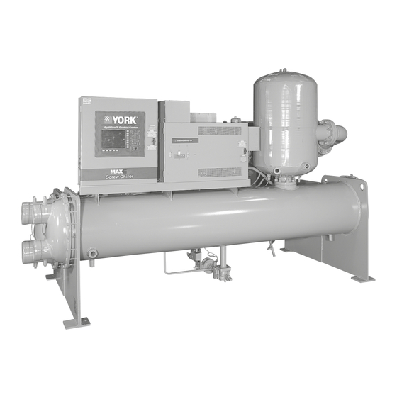
York YR TB TB T0 Installation Operation & Maintenance (76 pages)
ROTARY SCREW LIQUID CHILLERS, INCLUDING FIELD RE-ASSEMBLY FOR FORM 2, 3, 7 AND 8 SHIPMENT STYLE A AND B
Brand:
York
| Category:
Chiller
| Size: 4.25 MB
Table of Contents
Table of Contents
5
Section 1 - Installation
9
Construction Drawings
9
General
9
Installation Restrictions
9
TABLE 1 - Construction Drawings (Product Drawings) Issued by the Johnson Control Service Office
9
Clearance for Service Requirements
10
Data Plate
10
Foundation
10
Inspection - Damage - Shortage
10
Location
10
Rigging
10
TABLE 2 - Service Clearance Requirements
10
FIGURE 1 - Unit Rigging
11
TABLE 3 - Unit Weights
12
FIGURE 2 - Compressors - Evaporator, Condenser and Waterboxes Dimensions
14
FIGURE 3 - Standard Neoprene Vibration Isolator Pad Mounts (English)
16
FIGURE 5 - Spring Isolators (Optional) (English)
18
FIGURE 6 - Spring Isolators (Optional) (Metric)
19
FIGURE 7 - Model YR - Front View of Assembled Unit
20
Forms of Shipment
20
Shipping Form 2, 3, 7, and 8
20
Data Plate
21
Inspection - Damage - Shortage
21
Re-Assembly
21
FIGURE 4 - Standard Neoprene Vibration Isolator Pad Mounts (Metric)
17
Installing Optional Spring Isolators
18
TABLE 4 - Overall Dimensions
15
Checking the Isolator Pad Deflection
16
Locating and Installing Isolator Pads
16
FIGURE 8 - Rigging Compressor Assembly
21
TABLE 5 - Form 3 Field Assembly Parts
22
FIGURE 9 - Form 3 Field Assembly - Exploded View
23
FIGURE 10 - Form 7 Shipment
24
TABLE 6 - Form 7 Field Assembly Parts
25
FIGURE 11 - Form 7 Field Assembly - Exploded View
26
TABLE 7 - Form 8 Field Assembly Parts
27
TABLE 8 - Oil Quantities
27
FIGURE 13 - Saturation Curve
29
TABLE 9 - System Pressures
30
Check for Piping Alignment
31
Evaporator and Condenser Water Piping
31
Piping Connections
31
TABLE 10 - Water Flow Rate Limits - GPM (L/S)
32
FIGURE 14 - Schematic of a Typical Piping Arrangement
33
FIGURE 15 - Cooling Tower Piping with 3 Port By-Pass Valve
34
FIGURE 16 - Typical Refrigerant Vent Piping from Relief Valves
35
Control Wiring
36
Power Wiring
36
TABLE 11 - Refrigerant Relief Characteristics
36
Unit Piping
36
Installation Check - Request for Start-Up Service
37
Insulation
37
Refrigerant Relief Piping
35
FIGURE 12 - Form 8 Field Assembly - Exploded View
28
Operation
29
Vacuum Dehydration
29
FIGURE 17 - YR Motor Connections (Electro-Mechanical Starter)
37
Section 2 - Chiller Commissioning
41
Optiview Control Center
41
YR Chillers Pre-Startup Checklist
41
Condenser
41
Motor
41
Start-Up
42
Checking Operation
42
Operating Log Sheet
42
Chiller Commissioning
42
YR Chiller Start-Up
42
Customer (Operating Personnel) Instruction
43
Pre-Start Checklist
43
Section 3 - Operation
45
Basic Description
45
Components
45
FIGURE 18 - YR Screw Chiller Component Layout Drawing - Design Level "A
46
FIGURE 19 - YR Screw Chiller System Schematic - Design Level "A
47
FIGURE 20 - Oil Filter System
49
FIGURE 18 - YR Screw Chiller Component Layout Drawing - Design Level “A”
49
Oil Eductor Circuit
50
Capacity Control
51
Liquid Refrigerant Circuit
51
FIGURE 19 - YR Screw Chiller System Schematic - Design Level “A”
49
Oil System
49
TABLE 12 - Variable Orifice Pressure Differential Setpoints
51
FIGURE 22 - Variable Orifice
51
FIGURE 21 - Oil Solenoid Valve Assembly
51
Cycling Shutdowns
52
Need for Maintenance or Service
52
Normal Safety Shutdown and Repairs
52
Safety Shutdowns
52
Prolonged Shutdown
53
Start-Up after Prolonged Shutdown
53
Stopping the System
53
Section 4 - Operating Inspections
55
General
55
Section 5 - Maintenance
57
General
57
TABLE 14 - Maintenance Schedule
57
TABLE 13 - Operation / Inspection / Maintenance Requirements for York YR Chillers
57
Charging Unit with Oil
58
Compressor Oil
58
TABLE 16 - York Oil Type for R-134A
58
FIGURE 23 - Charging Oil
59
FIGURE 24 - Oil Filters
60
FIGURE 25 - Dual Oil Filter Isolation Valve
61
Determining Correct Refrigerant Charge Level
62
Pressure Connections
62
Refrigerant Charging
62
Refrigerant Leak Checking
62
TABLE 17 - Refrigerant Charge Level
62
Cleaning Evaporator and Condenser Tubes
63
Condenser Water Side Tube Cleaning Procedure
63
Condensers and Evaporators
63
Evaporator Tubes
64
Checking System for Leaks
65
FIGURE 26 - Diagram, Megohm Motor Windings
65
Megohm the Motor
65
Checking the Refrigerant Charge During Unit Shutdown
66
Evacuation and Dehydration of Unit
66
Commercial Acid Cleaning
67
Handling Refrigerant for Dismantling and Repairs
67
Testing for Evaporator and Condenser Tube Leaks
67
Tube Cleaning Procedures
67
Compressor
68
Electrical Controls
68
Vibration Analysis
68
Filter Drier Replacement
61
Oil Filter Replacement
61
TABLE 15 - Compressor Oil Limits
58
Oil Filter
60
Oil Temperature Control
60
FIGURE 27 - Evacuation of the Chiller
70
Section 6 - Troubleshooting
71
Abnormal Operation, Analysis and Correction
71
TABLE 18 - Troubleshooting
71
Troubleshooting Guide
71
Troubleshooting the Rotary Screw Compressor and Oil Separation System
71
Pressure/Temperature Conversion Tables
73
Temperature Conversion Tables
74
Temperature
75
TABLE 19 - si Metric Conversion
75
Advertisement
Advertisement
Related Products
York TLHA18-30OSAAAD
York TM9V*C
York THGD24
York TCHD60S41S3
York THGD24S41S1
York TCGD30S41S1
York TCGD24 S21S2
York TCGD30 S21S2
York TL9E100
York THE30B41S
York Categories
Air Conditioner
Heat Pump
Chiller
Furnace
Air Handlers
More York Manuals
Login
Sign In
OR
Sign in with Facebook
Sign in with Google
Upload manual
Upload from disk
Upload from URL