Sign In
Upload
Manuals
Brands
York Manuals
Chiller
YMC2
York YMC2 Manuals
Manuals and User Guides for York YMC2. We have
5
York YMC2 manuals available for free PDF download: Operation And Maintenance, Installation And Assembly Manual, Manual
York YMC2 Operation And Maintenance (146 pages)
CENTRIFUGAL LIQUID CHILLERS WITH R-134A OR R-513A REFRIGERANT
Brand:
York
| Category:
Chiller
| Size: 5.56 MB
Table of Contents
Table of Contents
6
Section 1 - System Fundamentals
11
System Components
11
FIGURE 1 - YMC 2 Chiller Components
11
FIGURE 2 - Optiview™ Control Center
13
System Operation Description
15
FIGURE 3 - Refrigerant Flow-Thru Chiller
18
Section 2 - System Operating Procedures
19
Pre-Starting
19
Condenser Water Temperature Control
19
Start-Up
19
Chiller Operation
20
Chilled Liquid Control Settings
20
TABLE 1 - Input Current Limit Threshold
20
TABLE 2 - Temperature Setpoint
20
Operator Setpoints Quick Reference
21
Stopping the System
21
Safety Stop
22
Operating Logs
22
Fault Shutdowns
22
FIGURE 4 - Liquid Chiller Log Sheets
22
Prolonged Shutdown
23
Restart after Prolonged Shutdown
23
TABLE 3 - Water Flow Rate Limits in GPM (L/S)-Based Upon Standard Tubes @ Design Full Load Conditions
24
Section 3 - Optiview™ Control Center Functions and Navigation
27
Interface Conventions
27
Analog Input Ranges
29
TABLE 4 - Analog Input Ranges
29
FIGURE 5 - Home Screen
30
FIGURE 6 - System Screen
32
FIGURE 7 - Evaporator Screen
34
FIGURE 8 - Condenser Screen
36
FIGURE 9 - Heat Pump Screen
38
FIGURE 10 - Compressor Screen
41
FIGURE 11 - Magnetic Bearing Controller Screen
43
FIGURE 12 - Magnetic Bearing Controller Details Screen
45
FIGURE 13 - Surge Screen
47
FIGURE 14 - Variable Geometry Diffuser Screen
49
FIGURE 15 - Power Panel Screen
50
FIGURE 16 - Capacity Controls Screen
52
FIGURE 17 - Variable Speed Drive Screen
54
FIGURE 18 - Variable Speed Drive (VSD) Details Screen
56
FIGURE 19 - Motor Details Screen
58
FIGURE 20 - Setpoints Screen
60
FIGURE 21 - Setup Screen
62
FIGURE 22 - Schedule Screen
65
FIGURE 23 - User Screen
67
FIGURE 24 - COMMS Screen
68
FIGURE 25 - Printer Screen
69
FIGURE 27 - Operations Screen
72
FIGURE 28 - History Screen
73
FIGURE 29 - History Details Screen
75
FIGURE 31 - Custom Setup Screen
77
FIGURE 32 - Trend Screen
78
FIGURE 33 - Trend Setup Screen
80
FIGURE 34 - Advanced Trend Setup Screen
82
FIGURE 35 - Common Slots Screen
84
Master Slot Numbers List for Use with Trend Feature
85
Display Messages
88
TABLE 5 - Status Messages
88
TABLE 6 - Run Messages
89
TABLE 7 - MBC Startup Messages
89
TABLE 8 - Start Inhibit Messages
90
TABLE 9 - Warning Messages
90
TABLE 10 - Routine Shutdown Messages
92
TABLE 11 - Cycling Shutdown Messages
93
TABLE 12 - Safety Shutdown Messages
100
FIGURE 26 - Sales Order Screen
105
Section 4 - Vsd Operation
111
Optispeed Compressor Drive Overview
111
Optispeed Compressor Drive Features
111
Optispeed Compressor Drive Details (0490 and 0774 Amp Drives)
112
Optispeed Compressor Drive Details (0490A, 0612A 0730A and 1278A Amp Drives)
113
FIGURE 36 - Left Side of Drive Cabinet (Typical for most of the Drive Models)
114
FIGURE 37 - Left Side of 1278A AMP Drive Cabinet
115
FIGURE 38 - Right Side of Drive Cabinet HYP0490
116
FIGURE 39 - Right Side of Drive Cabinet HYP0490A
116
FIGURE 40 - Right Side of Drive Cabinet HYP0612A
117
FIGURE 41 - Right Side of Drive Cabinet HYP0730A
117
FIGURE 42 - Right Side of Drive Cabinet HYP0774
118
FIGURE 43 - Center and Right Section of Drive Cabinet HYP1278A
118
FIGURE 44 - Drive Logic Board
119
FIGURE 45 - Rectifier Side of the Power Unit HYP0490, HYP0490A, HYP0612A and HYP0730A
119
Optispeed Compressor Drive and Chiller Operation (0490 and 0774 Amp Models)
120
FIGURE 46 - Rectifier Side of the Power Unit HYP0774 and HYP1278A
120
Optispeed Compressor Drive and Chiller Operation (0490A, 0612A, 0730A and 1278A Amp Models)
121
Section 5 - Maintenance
123
Preventative Maintenance
123
TABLE 13 - Maintenance Requirements
123
Renewal Parts
124
Operating Inspections
124
Checking System for Leaks
124
Conduct Pressure Test
124
System Evacuation
125
Vacuum Dehydration
125
FIGURE 47 - Evacuation of Chiller
126
TABLE 14 - System Pressures
126
FIGURE 48 - Saturation Curve
127
Conduct Pressure Test
128
Refrigerant Charging
128
Checking the Refrigerant Charge
128
Handling Refrigerant for Dismantling and Repairs
129
Compressor and Motor
129
Condensers and Evaporators
129
TABLE 15 - Approximate Refrigerant and Water Weight
129
Electrical Controls
131
Automatic Battery Health Test - During Shutdown
132
Section 6 - Printing
133
Printing Overview
133
Acceptable Printers
133
FIGURE 30 - Custom Screen
133
Printer Connections
134
Printer Setup
134
FIGURE 49 - OKIPOS Printer
134
Table 16 - Okidata Okipos 441
134
Printer Connections
135
Control Center Setup
135
FIGURE 50 - Breckman Printer
135
TABLE 17 - Brecknell CP130
135
Downloading System Prints to Alaptop
136
FIGURE 51 - Communications Block Diagram
137
FIGURE 52 - Optiview Panel to PC Serial Cable
137
FIGURE 53 - Sample Printout (Status or History)
138
FIGURE 54 - Sample Printout (Setpoints)
140
Temperature
145
TABLE 18 - si Metric Conversion
145
Advertisement
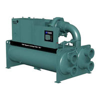
York YMC2 Installation And Assembly Manual (74 pages)
CENTRIFUGAL LIQUID CHILLERS WITH OPTIVIEW CONTROL CENTER
Brand:
York
| Category:
Chiller
| Size: 14.86 MB
Table of Contents
Table of Contents
5
Section 1 - Overview
9
General
9
Component Combinations
9
FIGURE 1 - YMC 2 Chiller Components
9
Inspection - Damage - Shortage
10
Chiller Data Plate
10
YMC 2 Shipment Forms
10
Form 1
10
Form 2
10
Form 3
10
Form 7
10
Form 9
10
Form 10
10
Form 11
14
Section 2 - Rigging and Lifting
15
Form 1 Total Weight
15
Form 1 Shipment
15
Unit Rigging
15
FIGURE 2 - Form 1 and 2 Rigging with Side Spreader Bar
16
FIGURE 3 - Form 1 and 2 Rigging Without Side Spreader Bar
16
Form 2 Total Weight
17
Form 2 Shipment
17
Unit Rigging
17
Form 3 Shipment
18
Shells
18
Compressor Motor Assembly
18
FIGURE 4 - Driveline Rigging
18
TABLE 1 - Compressor Motor Weights
18
Variable Speed Drive (VSD)
19
FIGURE 5 - Form 3 Rigging Without Side Spreader Bars
19
FIGURE 6 - Variable Speed Drive Rigging
19
TABLE 2 - Variable Speed Drive Weights
19
Power Panel
20
Optiview™ Control Center
20
FIGURE 7 - Power Panel
20
FIGURE 8 - Optiview Control Center
20
TABLE 3 - Power Panel
20
TABLE 4 - Control Panel Weights
20
Form 7 Shipment
21
Condenser
21
FIGURE 9 - Form 7 Rigging with Side Spreader Bars
21
Evaporator
22
Compressor Motor Assembly
22
Variable Speed Drive (VSD)
22
FIGURE 10 - Driveline Rigging
22
TABLE 5 - Compressor Motor Weights
22
TABLE 6 - Variable Speed Drive Weights
22
Power Panel
23
Optiview™ Control Center
23
FIGURE 11 - Variable Speed Drive Rigging
23
FIGURE 12 - Power Panel
23
TABLE 7 - Power Panel
23
TABLE 8 - Control Panel Weights
23
Form 9 Shipment
24
FIGURE 13 - Optiview Control Center
24
FIGURE 14 - Form 9 and 10 Rigging with Side Spreader Bars
24
FIGURE 15 - Form 9 and 10 Rigging Without Side Spreader Bars
25
TABLE 9 - Variable Speed Drive Weights
25
Unit Rigging
25
Variable Speed Drive (VSD)
25
Form 10 Shipment
26
Unit Rigging
26
Variable Speed Drive (VSD)
26
FIGURE 16 - Variable Speed Drive Rigging
26
TABLE 10 - Variable Speed Drive Weights
26
Form 11 Shipment
27
Condenser Assembly
27
FIGURE 17 - Variable Speed Drive Rigging
27
FIGURE 18 - Form 11 Condenser Assembly Rigging with Side Spreader Bars
28
FIGURE 19 - Form 11 Evaporator Assembly Rigging with Side Spreader Bars
28
Evaporator Assembly
29
Optiview™ Control Center
29
FIGURE 20 - Optiview Control Center
29
TABLE 11 - Control Panel Weights
29
Section 3 - Installation
31
Overview
31
Determine Location
31
Foundation Requirements
31
Clearance Requirements
31
Rig Unit to Final Location
31
Install Isolators
31
Neoprene Isolator Pads
31
FIGURE 21 - Neoprene Isolators
32
FIGURE 22 - Skid Options
33
Install Optional Spring Isolators
34
FIGURE 23 - Spring Isolators
34
Make Connections
35
Piping Connections
35
FIGURE 24 - Pressure Relief Piping
35
FIGURE 25 - Schematic of a Typical Piping Arrangement
36
Refrigerant Relief Piping
38
FIGURE 26 - Typical Refrigerant Vent Piping
38
Unit Piping
39
Control Wiring
39
Power Wiring
39
Supplied Variable Speed Drive
39
Apply Insulation
39
Installation Check - Request for Startup Service
39
FIGURE 27 - Unit Insulation
40
Section 4 - Reassembly
41
Form 3 and Form 7 Reassembly
41
FIGURE 28 - Shell Reassembly
41
TABLE 12 - Assembly Torque Metric for Metric Tube Fittings
42
TABLE 13 - Assembly Torque English for SAE Tube Fittings
42
FIGURE 29 - YMC 2 Piping Reassembly Hardware Identification
43
TABLE 14 - Re-Assembly Torque Values
43
FIGURE 30 - YMC 2 Form 3 Reassembly Hardware Identification
44
FIGURE 31 - YMC 2 Form 7 Reassembly Hardware Identification
45
FIGURE 32 - VSD Mounting Hardware Identification
46
FIGURE 33 - Power and Control Panel Mounting Hardware Identification
47
Form 9 and Form 10 Reassembly
48
FIGURE 34 - YMC 2 Form 9 and Form 10 Reassembly Hardware Identification
49
Form 11 Reassembly
50
FIGURE 35 - Shell Reassembly
50
FIGURE 36 - Refrigerant Piping
50
FIGURE 37 - YMC 2 Form 11 Reassembly Hardware Identification
51
Refrigerant Tubing Reassembly
52
Assembly of Straight Thread O-Ring Port Fittings
52
FIGURE 38 - Adjustable End Fitting
52
FIGURE 39 - Back off Locknut
52
FIGURE 40 - Screw Fitting into Port
52
Assembly of O-Ring Face Seal Fittings
53
FIGURE 41 - Torque Fitting
53
FIGURE 42 - SAE or ISO 6149 Straight Thread O-Ring Port
53
Section 5 - Dimensions, Nozzle Arrangements and Weights
55
Compressor Unit Dimensions
55
FIGURE 43 - Dimensions - 197 & 246 Compressor Units Ft-In (MM)
56
TABLE 15 - Evaporator Weights, Dry
58
TABLE 16 - Condenser Weights, Dry
58
Evaporator 150 & 300 PSI Compact Water Boxes
59
FIGURE 44 - Evaporator - Compact Water Boxes (1-Pass Nozzle Arrangements)
59
FIGURE 45 - Evaporator - Compact Water Boxes (2-Pass Nozzle Arrangements)
59
FIGURE 46 - Evaporator - Compact Water Boxes (3-Pass Nozzle Arrangements)
59
FIGURE 47 - Evaporator and Condenser - 150 & 300 Psi Compact Water Boxes
61
Condenser 150 & 300 PSI Compact Water Boxes
63
FIGURE 48 - Condenser - Compact Water Boxes (1-Pass Nozzle Arrangements)
63
FIGURE 49 - Condenser - Compact Water Boxes (3-Pass Nozzle Arrangements)
63
FIGURE 50 - Condenser - Compact Water Boxes (2-Pass Nozzle Arrangements)
63
Evaporator 150 & 300 PSI Marine Water Boxes
64
FIGURE 51 - Evaporator - Marine Water Boxes (1-Pass Nozzle Arrangements)
64
FIGURE 52 - Evaporator - Marine Water Boxes (2-Pass Nozzle Arrangements)
64
FIGURE 53 - Evaporator - Marine Water Boxes (3-Pass Nozzle Arrangements)
64
FIGURE 54 - Evaporator - 150 and 300 PSI Marine Water Boxes
66
Condenser 150 PSI Marine Water Boxes
67
FIGURE 55 - Condenser - Marine Water Boxes (1-Pass Nozzle Arrangements)
67
FIGURE 56 - Condenser - Marine Water Boxes (2-Pass Nozzle Arrangements)
67
FIGURE 57 - Condenser - Marine Water Boxes (3-Pass Nozzle Arrangements)
67
FIGURE 58 - Condenser - 150 and 300 PSI Marine Water Boxes
68
Condenser 150 & 300 PSI Marine Water Boxes Dimensions
69
Weights
70
TABLE 17 - Approximate Evaporator Weights 150 PSI Compact Water Boxes
70
TABLE 18 - Approximate Condenser Weights 150 PSI Compact Water Boxes
70
M6 Motor
71
TABLE 19 - Evaporator Weights, Dry
71
TABLE 20 - Condenser Weights, Dry
71
M6 Weights
72
TABLE 21 - VSD Weights
72
TABLE 22 - Compressor Weights
72
TABLE 23 - Unit Assembly - Panels, Piping, Wiring, Etc
72
TABLE 24 - Refrigerant & Water Weight
72
TABLE 25 - Approximate Variable Speed Drive (VSD) Weights
73
TABLE 26 - Approximate Driveline Weights
73
TABLE 27 - Approximate Refrigerant & Water Weight
73
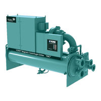
York YMC2 Manual (71 pages)
MAGNETIC BEARING CENTRIFUGAL LIQUID CHILLERS. 165-1000 Tons 580-3520 kW 50 & 60 Hz HFC-134a or HFC-513A
Brand:
York
| Category:
Chiller
| Size: 2.71 MB
Table of Contents
FORM 160.84-EG1 (617)Nomenclature
2
Table of Contents
3
Introduction
5
Ratings
8
Product View
10
Unit Components
10
Equipment Overview
12
Optiview Control Center
17
System Screen
18
Evaporator Screen
19
Condenser Screen
19
Compressor Screen
20
Magnetic Bearing Controller
20
Capacity Control
21
Variable Geometry Diffuser
21
Setpoints
22
Variable Speed Drive (VSD)
22
History
23
Display Messages
23
Optispeed Variable-Speed Drive
24
Accessories and Modifications
26
Location
27
Water Circuits
27
Application Data
27
Temperature Ranges
28
Water Quality
28
General Piping
28
Connections
28
Parallel Arrangement
29
Multiple Units
29
Condenser Water
29
Series/Parallel Arrangement
30
Series Counter Flow Arrangement
30
Refrigerant Relief Piping
31
Sound and Vibration Considerations
31
Thermal Insulation
31
Ventilation
31
Electrical Considerations
32
Voltage Variations
32
Displacement Power-Factor Correction Capacitors
32
Branch Circuit Overcurrent Protection
32
Water Fow Rate Limits in GPM (L/S)
33
Unit Dimensions
38
Weights
56
Compressor
63
Guide Specifications
63
Motor
64
Variable-Speed Drive (VSD)
64
Evaporator
65
Condenser
65
Refrigerant Flow Control
66
Refrigerant Isolation Valves
66
Optiview Control Center
66
Startup and Operation Training
67
Factory Insulation
67
Isolation Mounting
67
Metric (SI) Conversion
68
Advertisement
York YMC2 Manual (36 pages)
Centrifugal Liquid Chillers
Brand:
York
| Category:
Chiller
| Size: 2.84 MB
Table of Contents
Table of Contents
5
Section 1 - Shipping
7
General
7
Component Combinations
7
Figure 1 - YMC 2 Chiller Components
7
Table 1 - Allowable Motor, Compressor, Evaporator, and Condenser Combinations
7
Field Assembled Units Only
8
YMC 2 Shipment Forms
8
Form 1
8
Form 2
8
Form 3
8
Form 7
8
Form 9
8
Form 10
8
Form 11
8
Inspection, Damage, and Shortage
12
Chiller Data Plate
12
Section 2 - Installation
13
Overview
13
Rig Chiller Unit
13
Figure 2 - Rigging
13
Determine Location
14
Foundation Requirements
14
Clearance Requirements
14
Rig Unit to Final Location
14
Install Isolators
14
Neoprene Isolator Pads
14
Figure 3 - Neoprene Isolators
15
Figure 4 - Neoprene Isolators
16
Install Optional Spring Isolators
17
Figure 5 - Spring Isolators
17
Figure 6 - Spring Isolators
18
Make Connections
19
Piping Connections
19
Figure 7 - Typical Refrigerant Vent Piping
19
Figure 8 - Schematic of a Typical Piping Arrangement
20
Refrigerant Relief Piping
21
Unit Piping
21
Control Wiring
21
Power Wiring
21
Supplied Variable Speed Drive
21
Figure 9 - FAA Unit Insulation
22
Figure 10 - FAB Unit Insulation
23
Apply Insulation
24
Installation Check - Request for Start-Up Service
24
Section 3 - Dimensions, Nozzle Arrangements, and Weights
25
Compressor Unit Dimensions
25
Figure 11 - Dimensions of 197 and 205 Compressor Units, Ft-In. (MM)
25
Evaporator Nozzle Arrangements (150 Psi Compact Waterboxes)
26
Figure 12 - Evaporators - Compact Waterboxes (1-Pass Nozzle Arrangements)
26
Figure 13 - Evaporators - Compact Waterboxes (2-Pass Nozzle Arrangements)
26
Figure 14 - Evaporators - Compact Waterboxes (3-Pass Nozzle Arrangements)
26
Figure 15 - Evaporators - 150 Psi Compact Waterboxes
27
Condenser Nozzle Arrangements (150 Psi Compact Waterboxes)
28
Figure 16 - Condensers - Compact Waterboxes (1-Pass Nozzle Arrangements)
28
Figure 17 - Condensers - Compact Waterboxes (3-Pass Nozzle Arrangements)
28
Figure 18 - Condensers - Compact Waterboxes (2-Pass Nozzle Arrangements)
28
Figure 19 - Condensers - 150 Psi Compact Waterboxes
29
Evaporator Nozzle Arrangements (150 Psi Marine Waterboxes)
30
Figure 20 - Evaporators - Marine Waterboxes (1-Pass Nozzle Arrangements)
30
Figure 21 - Evaporators - Marine Waterboxes (2-Pass Nozzle Arrangements)
30
Figure 22 - Evaporators - Marine Waterboxes (3-Pass Nozzle Arrangements)
30
Figure 23 - Evaporators - 150 Psi Marine Waterboxes
31
Condenser Nozzle Arrangements (150 Psi Marine Waterboxes)
32
Figure 24 - Condensers - Marine Waterboxes (1-Pass Nozzle Arrangements)
32
Figure 25 - Condensers - Marine Waterboxes (2-Pass Nozzle Arrangements)
32
Figure 26 - Condensers - Marine Waterboxes (3-Pass Nozzle Arrangements)
32
Figure 27 - Condensers - 150 Psi Marine Waterboxes
33
Weights
34
150 Psi Compact and Marine Waterboxes, Lb (Kg)
34
Table 2 - Approximate Unit Weight* (Max Tube Count Using 150 Psi Compact Waterboxes)
34
Table 3 - Evaporator Marine Waterbox Weights (to be Added to Standard Unit Weights Shown on Table 2)
34
Table 4 - Condenser Marine Waterbox Weights (to be Added to Standard Unit Weights Shown on Table 2)
34
Table 5 - si Metric Conversion
35
York YMC2 Manual (8 pages)
Brand:
York
| Category:
Chiller
| Size: 0.25 MB
Advertisement
Related Products
York YMC2 A
York Latitude YCIV0357E
York Millennium YCAS 1263
York YCWJ45EE0
York Millennium YDAS 410
York YCAL0051EC
York YHAU-CGN-120EXS
York YMFFZH018-060BAM-BFX
York YMAA 0130
York YMPA 0045
York Categories
Air Conditioner
Heat Pump
Chiller
Furnace
Air Handlers
More York Manuals
Login
Sign In
OR
Sign in with Facebook
Sign in with Google
Upload manual
Upload from disk
Upload from URL