Sign In
Upload
Manuals
Brands
York Manuals
Chiller
YD A
York YD A Manuals
Manuals and User Guides for York YD A. We have
2
York YD A manuals available for free PDF download: Operation Manual, Operating & Maintenance
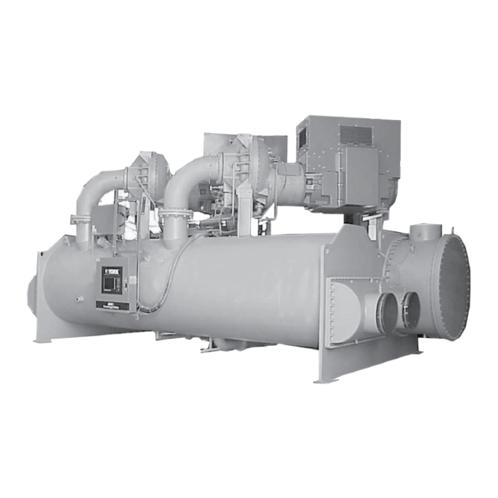
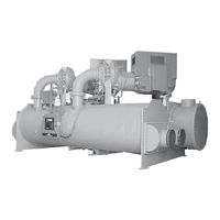
York YD A Operation Manual (150 pages)
OPTIVIEW CONTROL CENTER CENTRIFUGAL LIQUID CHILLERS
Brand:
York
| Category:
Chiller
| Size: 5.15 MB
Table of Contents
Table of Contents
5
FIGURE 1 - Model YD Chiller
9
Compressor Starting
10
Compressor Shutdown
14
Section 1 - Description of System and Fundamentals of Operation
9
System Operation Description
9
FIGURE 2 - Chiller Operation Flow Chart
15
Section 2 - Optiview Control Center
23
Introduction
23
FIGURE 3 - Optiview™ Control Center
25
FIGURE 4 - Home Screen
30
FIGURE 5 - System Screen
33
Evaporator Screen
35
FIGURE 6 - Evaporator Screen
35
Condenser Screen
38
FIGURE 7 - Condenser Screen
38
FIGURE 8 - Refrigerant Level Control Screen
40
Refrigerant Level Control Screen
40
FIGURE 9 - Main Compressor Screen
42
Main Compressor Screen
42
Compressor 1 Screen
44
FIGURE 10 - Compressor 1 Screen
44
Compressor 2 Screen
46
FIGURE 11 - Compressor 2 Screen
46
FIGURE 12 - Proximity Probe Calibration Screen
48
Proximity Probe Calibration Screen
48
FIGURE 13 - Pre-Rotation Vanes Calibration Screen
50
Pre-Rotation Vanes Calibration Screen
50
FIGURE 14 - Variable Geometry Diffuser 1 Screen
51
Variable Geometry Diffuser (VGD) 1 Screen
51
FIGURE 15 - Variable Geometry Diffuser 2 Screen
53
Variable Geometry Diffuser (VGD) 2 Screen
53
FIGURE 16 - Variable Geometry Diffuser Setpoints Screen
55
Variable Geometry Diffuser (VGD) Setpoints Screen
55
Vgd 1
55
Vgd 2
56
Vgd 1
57
Vgd 2
57
FIGURE 17 - Variable Geometry Diffuser 1 Calibration Screen
58
Variable Geometry Diffuser (VGD) 1 Calibration Screen
58
Display Only
59
FIGURE 18 - Variable Geometry Diffuser Setpoints Screen
59
Variable Geometry Diffuser (VGD) 2 Calibration Screen
59
FIGURE 19 - Hot Gas Bypass Screen
60
Hot Gas Bypass Screen
60
FIGURE 20 - Surge Protection Screen
62
Surge Protection Screen
62
FIGURE 21 - Surge Protection Screen (Single Compressor Operation)
64
Surge Protection Screen (Single-Compressor Operation)
64
FIGURE 22 - Surge Protection Screen (Dual Compressor Operation)
67
Surge Protection Screen (Dual-Compressor Operation)
67
Capacity Compressor Cycling Screen
69
FIGURE 23 - Capacity Compressor Cycling
69
FIGURE 24 - Oil Sump Screen
73
Oil Sump Screen
73
FIGURE 25 - Oil Pump 1 Screen
75
Oil Pump 1 Screen
75
FIGURE 26 - Oil Pump 2 Screen
77
Oil Pump 2 Screen
77
Electro-Mechanical Starter Screen
79
FIGURE 27 - Electro-Mechanical Starter Screen
79
FIGURE 28 - Motor Lubrication Screen
83
Motor Lubrication Screen
83
FIGURE 29 - Setpoints Screen
86
Setpoints Screen
86
FIGURE 30 - Setup Screen
89
Setup Screen
89
FIGURE 31 - Schedule Screen
92
Schedule Screen
92
FIGURE 32 - User Screen
94
User Screen
94
Comms Screen
95
FIGURE 33 - Comms Screen
95
FIGURE 34 - Printer Screen
96
Printer Screen
96
FIGURE 35 - Sales Order Screen
97
Sales Order Screen
97
FIGURE 36 - Operations Screen
98
Operations Screen
98
FIGURE 37 - History Screen
100
History Screen
100
FIGURE 38 - History Details Page
102
History Details Screen
102
FIGURE 39 - Security Log Screen
103
Security Log Screen
103
FIGURE 40 - Security Log Screen
104
Security Log Details Screen
104
Custom View Screen
105
FIGURE 41 - Custom View Screen
105
Custom View Setup
106
FIGURE 42 - Custom View Setup Screen
106
FIGURE 43 - Trend Screen
107
Trend Screen
107
FIGURE 44 - Trend Setup Screen
109
Trend Setup Screen
109
Advanced Trend Setup Screen
111
FIGURE 45 - Advanced Trend Setup Screen
111
Common Slots Screen
113
FIGURE 46 - Common Slots Screen
113
Slot Numbers
114
Display Messages
115
Start Inhibit Messages
117
System Screen
33
Optiview Control Center
25
Interface Conventions
26
Analog Input Ranges
29
Home Screen
30
Section 3 - Printers
135
FIGURE 47 - Printer
135
Printing Overview
135
Acceptable Printers
136
Printer Connections
136
Control Center Setup
137
Downloading System Prints to Alaptop
137
Printer Setup
137
FIGURE 48 - Communications Block Diagram
139
FIGURE 49 - Sample Printout (Status)
140
FIGURE 50 - Sample Printout (Setpoints)
142
FIGURE 51 - Sample Printout (Schedule)
144
FIGURE 52 - Sample Printout (Sales Order)
144
FIGURE 53 - Sample Printout (History)
146
FIGURE 54 - Sample Printout (Security Log Report)
148
FIGURE 55 - Sample Printout (Trend Data New or Existing Points)
148
FIGURE 56 - Sample Printout (Custom Screen Report)
148
Advertisement
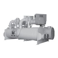
York YD A Operating & Maintenance (52 pages)
CENTRIFUGAL LIQUID CHILLERS WITH OPTIVIEW CONTROL CENTER AND ELECTRO-MECHANICAL STARTER COOLING ONLY
Brand:
York
| Category:
Chiller
| Size: 1.99 MB
Table of Contents
Table of Contents
5
FIGURE 1 - Model YD Chiller
9
Compressor Starting
10
Compressor Shutdown
14
Section 1 - Description of System and Fundamentals of Operation
9
System Operation Description
9
FIGURE 2 - Chiller Operation Flow Chart
15
FIGURE 3 - Oil Level Indicator
23
Chiller Operation
24
Start-Up
24
Condenser Water Temperature Control
25
Operating Log Sheet
25
Section 2 - System Operating Procedures
23
Checking the Oil Level in the Oil Reservoir
23
Oil Heater Operation
23
Oil Heaters
23
Start-Up Procedure
23
FIGURE 4 - Liquid Chiller Log Sheets
25
Operating Inspections
26
Need for Maintenance or Service
27
Prolonged Shutdown
27
Stopping the System
27
Section 3 - System Components Description
29
Capacity Control
29
Compressor
29
Compressor Lubrication System
29
General
29
FIGURE 5 - System Components
30
Oil Pump
30
FIGURE 6 - Schematic Drawing - (YD) Compressor Lubrication System
31
FIGURE 7 - Oil Return System
35
Oil Charging Procedure
36
The Oil Charge
36
Heat Exchangers
32
Motor Driveline
32
Oil Heater
32
Refrigerant Flow Control
32
Optional Hot Gas Bypass
33
Optiview™ Control Center
33
Section 4 - Operational Maintenance
35
Oil Return System
35
Changing the Dehydrator
35
FIGURE 8 - Charging Oil Reservoir with Oil
36
TABLE 1 - Operation Analysis Chart
37
Section 5 - Troubleshooting
37
FIGURE 9 - Evacuation of Chiller
39
Vacuum Testing
40
Section 6 - Maintenance
39
Checking System for Leaks
39
Conducting R-22 Pressure Test
39
TABLE 2 - System Pressures
40
FIGURE 10 - Saturation Curve
41
TABLE 3 - Refrigerant Charge
42
Checking the Refrigerant Charge During Unit Shutdown
43
Handling Refrigerant for Dismantling and Repairs
43
Megging the Motor
43
Refrigerant Charging
42
Operation
41
Vacuum Dehydration
41
FIGURE 11 - Megging Motor Windings
43
FIGURE 12 - Motor Starter Temperature and Insulation Resistances
44
Chemical Water Treatment
45
Cleaning Evaporator and Condenser Tubes
45
Condensers and Evaporators
45
General
45
Tube Cleaning Procedures
45
Tube Fouling
45
Acid Cleaning of Tubes
46
Commercial Acid Cleaning
46
Testing for Evaporator and Condenser Tube Leaks
46
Compressor
47
Electrical Controls
47
Section 7 - Preventive Maintenance
49
Compressor
49
Compressor Motor
49
Greased Bearings on Reliance Q5800 Motors
49
TABLE 4 - Bearing Lubrication
49
Electrical Controls
50
Evaporator and Condenser
50
Leak Testing
50
Oil Return System
50
TABLE 5 - si Metric Conversion
51
Metric Conversion
51
Temperature
51
Advertisement
Related Products
York YDAJ87KU6
York YDAJ88MU6
York YDAJ99MW6
York YDAJ87HU7
York YDAJ97KU7
York YDAJ98MU7
York YDAJ99MU7
York YDAJ99MW9
York Millennium YDAS 410
York Millennium YDAS 490
York Categories
Air Conditioner
Heat Pump
Chiller
Furnace
Air Handlers
More York Manuals
Login
Sign In
OR
Sign in with Facebook
Sign in with Google
Upload manual
Upload from disk
Upload from URL