Sign In
Upload
Manuals
Brands
York Manuals
Chiller
YD
York YD Manuals
Manuals and User Guides for York YD. We have
3
York YD manuals available for free PDF download: Installation Manual, Manual, Wiring Diagram
York YD Installation Manual (32 pages)
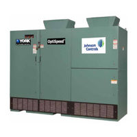
Medium Voltage 500 hp to 2500 hp, 2300 V, 3300 V, 4160 V, and 6600 V, 60 Hz 3300 V and 6600 V 50 Hz Variable Speed Drives
Brand:
York
| Category:
Chiller
| Size: 2.08 MB
Table of Contents
Table of Contents
6
TABLE 1 - Unit Model Reference
8
Section 1 - Field Connection Notes
11
TABLE 2 - Oil Pump/Drive Power Supply
11
TABLE 3 - Minimum Voltage During Start-Up
12
Section 2 - Equipment Grounding
13
General
13
Equipment Grounding
13
Grounding Procedure Needed to Ensure Electrical Noise Immunity
13
FIGURE 1 - Grounding Details
15
FIGURE 2 - Unit Dimensions (74 In. X 44 In. X 104 In.)
16
FIGURE 3 - Unit Dimensions (122 In. X 44 In. X 104 In.)
17
FIGURE 4 - Unit Dimensions (164 In. X 50 In. X 104 In.)
18
FIGURE 5 - Unit Dimensions (174 In. X 50 In. X 104 In.)
19
Section 3 - Installation
21
General
21
Handling and Storage
21
Inspection
21
Safety Precautions
21
Drive Lifting and Assembly
22
FIGURE 6 - Unit Clearances
22
FIGURE 7 - Lifting and Assembly
23
FIGURE 8 - Modbus Connections
24
Grounding
25
Control Wiring
24
Electrical Connection
24
Power Wiring
24
Location
22
Mounting
23
Mounting Requirements
23
FIGURE 10 - Ground Bus Splice Connection
25
FIGURE 9 - Motor Lead Connections
25
FIGURE 11 - Oil Pump Connections
26
Oil Pump Wiring
26
TABLE 5 - Control and Oil Pump Wire Numbers and Termination Points for YD-SYS 1 and YD-SYS 2
26
TABLE 4 - Control and Oil Pump Wire Numbers and Termination Points for YK Chiller
26
TABLE 6 - Control and Oil Pump Wire Numbers and Termination Points for YKEP-SYS 1
27
Device/Mechanism Check
28
Electrical Checks
28
Initial Energization
28
Start-Up and Test
29
Confirmation of Wiring
27
Pre-Energization Check
27
Upstream Protection
27
TABLE 7 - si Metric Conversion
31
Advertisement
York YD Wiring Diagram (20 pages)
Brand:
York
| Category:
Chiller
| Size: 0.85 MB
Table of Contents
Table of Contents
5
Section 1 - Energy Managements Systems
7
Section 2 - Field Control Modifications
9
Remote Mode Ready to Start Contact
9
Cycling Shutdown Contacts
9
Safety Shutdown Contacts
9
FIGURE 1 - Remote Mode Ready to Start Contacts
9
FIGURE 2 - Cycling Shutdown Contacts
9
FIGURE 3 - Safety Shutdown Contacts
9
Run Contacts
10
Remote Run-Stop Contacts from EMS
10
FIGURE 4 - Run Contacts (Compressor #1)
10
FIGURE 5 - Run Contacts (Compressor #2)
10
FIGURE 6 - Anticipatory/Alarm Contacts
10
FIGURE 7 - Remote Start-Stop Contacts from Energy Management Systems
10
Remote/Local Cycling Devices
11
Multi-Unit Sequence
11
Condenser Flow Sensors
11
FIGURE 8 - Remote/Local Cycling Devices Compressor #1
11
FIGURE 9 - Remote/Local Cycling Devices Compressor #2
11
FIGURE 10 - Multi-Unit Sequence
11
FIGURE 11 - Condenser Flow Sensors
11
Thermal Type Flow Sensor
12
Digital-Type Flow Sensors
12
Electro-Mechanical Starter Manual Reset Overloads
12
FIGURE 12 - Paddle/Dp Type Flow Sensor
12
FIGURE 13 - Electro-Mechanical Starter Manual Reset Overloads (2300 to 4160 Volts U.l. or C.S.A. Approved Units Only)
12
Remote Current Limit Setpoint with 0-10VDC, 2-10VDC, 0-20Ma, 4-20Ma, or Pulse Width Modulation Signal
13
FIGURE 14 - Electro-Mechanical Starter Manual Reset Overloads (2300 to 4160 Volts U.l. or C.S.A. Approved Units Only)
13
FIGURE 15 - Remote Current Limit Setpoint with 0-10VDC or 2-10VDC Signal
13
Remote Leaving Chilled Liquid Setpoint with 0-10VDC, 2-10VDC, 0-20Ma, 4-20Ma, or Pulse Width Modulation Signal
14
FIGURE 16 - Remote Current Limit Setpoint with 0-20Ma or 4-20Ma Signal
14
FIGURE 17 - Remote Current Limit Setpoint with PWM Signal
14
FIGURE 18 - Remote Current Limit Setpoint with 0-1VDC or 2-10VDC Signal
15
Remote Leaving Chilled Liquid Temperature Setpoint with PWM Signal
16
FIGURE 19 - Remote Leaving Chilled Liquid Temperature Setpoint with 0-20Ma or 4-20Ma Signal
16
External Signal for Refrigeration Unit Failure
17
Configured for Manual Restart after Power Failure
17
FIGURE 20 - Remote Leaving Chilled Liquid Temperature Setpoint with PWM Signal
17
FIGURE 21 - External Signal for Refrigeration Unit Failure (Note 6)
17
FIGURE 22 - Auxiliary Safety Shutdown Input
17
Thermal Type Flow Sensor
18
Paddle/Dp Type Flow Sensor
18
Digital-Type Flow Sensors
18
FIGURE 23 - Evaporator Flow Sensors
18
FIGURE 24 - Paddle/Dp Type Flow Sensor
18
York YD Manual (24 pages)
CENTRIFUGAL LIQUID CHILLERS
Brand:
York
| Category:
Chiller
| Size: 3.13 MB
Table of Contents
Table of Contents
5
FIGURE 1 - Front View of Assembled Unit
7
FIGURE 2 - Form 7 Shipment
8
TABLE 1 - Dimensions - K Compressor Units Ft.-In.(MM)
10
FIGURE 3 - Dimensions - K Compressor Units Ft.-In. (MM)
11
TABLE 2 - Approximate Unit Weight Including Motor* - English (Metric)
12
TABLE 3 - Marine Waterbox Weight - English (Metric)
12
FIGURE 4 - 150 # Design Evaporator, no Hot Gas Bypass
13
TABLE 4 - Evaporator Shell Weights - 150# Design, no Hot Gas Bypass
13
TABLE 5 - Condenser Shell Weights - 150# Design, no Hot Gas Bypass
14
FIGURE 5 - 150 # Design Condenser, no Hot Gas Bypass
15
FIGURE 6 - Rigging - Driveline Assembly
16
TABLE 6 - Compessor Weights
16
TABLE 7 - Approximate Unit Motor Weights - English (Metric)
17
TABLE 8 - Suction/Discharge Piping
18
FIGURE 7 - Oil Pump Housing
19
FIGURE 8 - Liquid Line Re-Assembly
19
FIGURE 9 - High Pressure Cutout Tubing
19
FIGURE 10 - System Piping
19
FIGURE 11 - Re-Assembly
20
FIGURE 12 - Variable Speed Drive Bracket
21
TABLE 9 - VSD Weight
21
FIGURE 14 - Variable Speed Drive Rigging
22
TABLE 10 - si Metric Conversion
23
Advertisement
Advertisement
Related Products
York YD Series
York YD A
York YD B
York YDAJ87KU6
York YDAJ88MU6
York YDAJ99MW6
York YDAJ87HU7
York YDAJ97KU7
York YDAJ98MU7
York YDAJ99MU7
York Categories
Air Conditioner
Heat Pump
Chiller
Furnace
Air Handlers
More York Manuals
Login
Sign In
OR
Sign in with Facebook
Sign in with Google
Upload manual
Upload from disk
Upload from URL