Sign In
Upload
Manuals
Brands
Vaisala Manuals
Transmitter
WXT520
Vaisala WXT520 Manuals
Manuals and User Guides for Vaisala WXT520. We have
1
Vaisala WXT520 manual available for free PDF download: User Manual
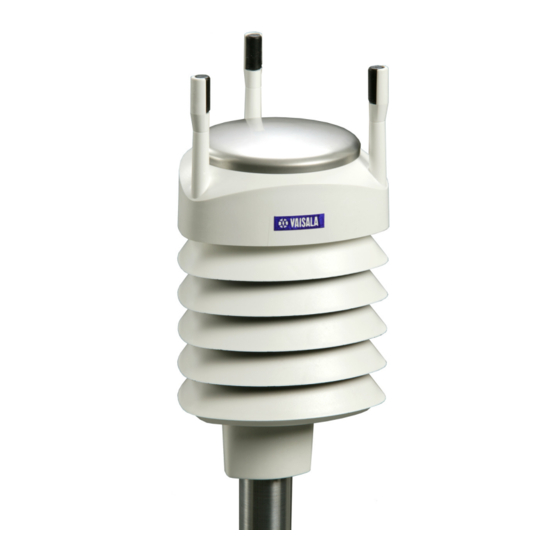
Vaisala WXT520 User Manual (171 pages)
Weather Transmitter
Brand:
Vaisala
| Category:
Transmitter
| Size: 3.39 MB
Table of Contents
Table of Contents
3
Chapter 1 General Information
13
About this Manual
13
Contents of this Manual
13
General Safety Considerations
14
Feedback
15
ESD Protection
15
Recycling
15
Trademarks
16
License Agreement
16
Regulatory Compliance
16
Warranty
17
Chapter 2 Product Overview
19
Weather Transmitter WXT520
19
Figure 1 Vaisala Weather Transmitter WXT520
19
Heating Function
20
Optional Software for Easy Settings
20
WXT520 Transmitter Components
21
Figure 2 Main Components of Weather Transmitter WXT520
21
Figure 3 Cut Away View
22
Figure 4 Bottom of Transmitter
23
Figure 5 Mounting Kit (Optional)
24
Figure 6 USB Cables (Optional)
24
Figure 7 Bird Spike Kit (Optional)
25
Figure 8 Surge Protector (Optional)
26
Chapter 3 Functional Description
27
Wind Measurement Principle
27
Precipitation Measurement Principle
29
PTU Measurement Principle
31
Heating (Optional)
31
Figure 9 Heating Control
32
Chapter 4 Installation
33
Unpacking the Transmitter
33
Selecting the Location
34
Figure 10 Recommended Mast Location in an Open Area
34
Figure 11 Recommended Mast Length on Top of a Building
35
Installation Procedure
36
Mounting
36
Mounting to Vertical Pole Mast
36
Mounting with Mounting Kit (Optional)
37
Figure 12 Location of Fixing Screw
37
Figure 13 Mounting WXT520 to Pole Mast Using Optional Mounting
38
Mounting to Horizontal Cross Arm
39
Figure 14 Mounting WXT520 to Cross Arm (L-Profile)
39
Grounding the WXT520
40
Grounding Using the Bushing and Grounding Kit
40
Figure 15 Mounting Bolt Location in Cross Arm
40
Marine Grounding Jumper
41
Figure 16 Grounding Using the Bushing and Grounding Kit
41
Figure 17 Grounding Jumper Location
42
Aligning WXT520
43
Compass Alignment
43
Figure 18 Sketch of Magnetic Declination
43
Wind Direction Offset
44
Figure 19 Wind Direction Offset
44
Chapter 5 Wiring and Power Management
45
Power Supplies
45
Figure 20 Average Operational Current Consumption
46
Figure 21 Heating Current and Power Vs Vh
47
Wiring Using the 8-Pin M12 Connector
48
External Wiring
48
Figure 22 Pins of 8-Pin M12 Connector
48
Table 1 Pin-Outs for WXT520 Serial Interfaces and Power Supplies
48
Internal Wiring
49
Figure 23 Internal Wiring
49
Chapter 6
49
Wiring Using the Screw Terminals
50
Figure 24 Screw Terminal Block
50
Data Communication Interfaces
52
Figure 25 Data Communication Interfaces
52
Power Management
53
Chapter 6 Connection Options
57
Communication Protocols
57
Table 3 Available Serial Communication Protocols
57
Connection Cables
58
Table 4 Connection Cable Options
58
Installing the Driver for the USB Cable
59
Service Cable Connection
60
Connection through M12 Bottom Connector or Screw Terminal
61
Table 5 Default Serial Communication Settings for M12/Screw Terminal Connection
61
Communication Setting Commands
62
Checking the Current Communication Settings (Axu)
62
Setting Fields
63
Changing the Communication Settings (Axu)
65
Chapter 7 Getting the Data Messages
67
General Commands
68
Reset (Axz)
68
Precipitation Counter Reset (Axzru)
69
Precipitation Intensity Reset (Axzri)
70
Measurement Reset (Axzm)
71
ASCII Protocol
72
Abbreviations and Units
72
Table 6 Abbreviations and Units
72
Device Address (?)
73
Acknowledge Active Command (A)
73
Wind Data Message (Ar1)
74
Pressure, Temperature and Humidity Data Message
75
(Ar2)
75
Precipitation Data Message (Ar3)
76
Supervisor Data Message (Ar5)
77
Combined Data Message (Ar)
78
Composite Data Message Query (Ar0)
78
Polling with CRC
79
Automatic Mode
81
Automatic Composite Data Message (Ar0)
81
SDI-12 Protocol
82
Address Query Command (?)
83
Acknowledge Active Command (A)
83
Change Address Command (Aab)
84
Send Identification Command (Ai)
85
Start Measurement Command (Am)
85
Start Measurement Command with CRC (Amc)
87
Start Concurrent Measurement (Ac)
87
Start Concurrent Measurement with CRC (Acc)
88
Send Data Command (Ad)
89
Examples of Am, Ac and Ad Commands
90
Continuous Measurement (Ar)
92
Continuous Measurement with CRC (Arc)
94
Start Verification Command (Av)
94
NMEA 0183 V3.0 Protocol
95
Device Address (?)
95
Acknowledge Active Command (A)
96
MWV Wind Speed and Direction Query
96
XDR Transducer Measurement Query
98
Table 7 Transducer Ids of the Measurement Parameters
100
TXT Text Transmission
106
Table 8 Transducer Table
106
Automatic Mode
108
Automatic Composite Data Message (Ar0)
108
Chapter 8 Sensor and Data Message Settings
109
Wind Sensor
109
Checking the Settings (Awu)
109
Setting Fields
111
Changing the Settings (Awu)
113
Pressure, Temperature, and Humidity Sensors
115
Checking the Settings (Atu)
115
Setting Fields
116
Changing the Settings (Atu)
117
Precipitation Sensor
119
Checking the Settings (Aru)
119
Setting Fields
120
Changing the Settings (Aru)
123
Supervisor Message
125
Checking the Settings (Asu)
125
Setting Fields
126
Changing the Settings (Asu)
127
Composite Data Message (Ar0)
129
Chapter 9 Maintenance
131
Cleaning
131
Replacing the PTU Module
132
Figure 26 Replacing the PTU Module
132
Factory Calibration and Repair Service
133
Vaisala Service Centers
133
Chapter 10 Troubleshooting
135
Table 9 Data Validation
135
Table 10 Communication Problems
136
Self-Diagnostics
137
Error Messaging/Text Messages
137
Table 11 Error Messaging/Text Messages Table
138
Rain and Wind Sensor Heating Control
139
Operating Voltage Control
139
Technical Support
139
Chapter 11 Technical Specifications
141
Performance
141
Table 12 Barometric Pressure
141
Table 13 Air Temperature
141
Figure 27 Accuracy over Temperature Range
142
Table 14 Wind
142
Table 15 Relative Humidity
142
Table 16 Precipitation
143
Inputs and Outputs
144
Table 17 Inputs and Outputs
144
Operating Conditions
145
Table 18 Operating Conditions
145
Table 19 Electromagnetic Compatibility
145
Materials
146
General
146
Table 20 Materials
146
Table 21 General
146
Options and Accessories
147
Table 22 Options and Accessories
147
Dimensions (MM/Inch)
148
Figure 28 WXT520 Dimensions, Side View
148
Figure 29 WXT520 Dimensions, Top and Bottom View
149
Figure 30 Mounting Kit Dimensions
150
Appendix Anetworking
151
Connecting Several Wxt520S on the same Bus
151
SDI-12 Serial Interface
151
Wiring
151
Communication Protocol
152
RS-485 Serial Interface
153
Wiring
153
Communication Protocol
153
ASCII, Polled
153
NMEA 0183 V3.0, Query
154
NMEA 0183 V3.0 Query with ASCII Query Commands
156
Appendix B Sdi-12 Protocol
159
SDI-12 Electrical Interface
159
SDI-12 Communications Protocol
160
SDI-12 Timing
161
Figure 31 Timing Diagram
161
Appendix C Crc-16 Computation
163
Encoding the CRC as ASCII Characters
164
NMEA 0183 V3.0 Checksum Computation
164
Appendix D
165
Wind Measurement Averaging Method
165
Figure 32 Wind Measurement Averaging Method
166
Appendix E Factory Configurations
167
General Unit Settings
168
Wind Configuration Settings
168
Table 23 General Unit Settings
168
Table 24 Wind Configuration Settings
168
PTU Configuration Settings
169
Rain Configuration Settings
169
Supervisor Settings
169
Table 25 PTU Configuration Settings
169
Table 26 Rain Configuration Settings
169
Table 27 General Unit Settings
169
Advertisement
Advertisement
Related Products
Vaisala WXT510
Vaisala WXT536
Vaisala WXT532
Vaisala WXT533
Vaisala WXT535
Vaisala WXT534
Vaisala WXT531
Vaisala WXT530 Series
Vaisala WS425 F/G
Vaisala WAT12
Vaisala Categories
Transmitter
Measuring Instruments
Accessories
Weather Station
Test Equipment
More Vaisala Manuals
Login
Sign In
OR
Sign in with Facebook
Sign in with Google
Upload manual
Upload from disk
Upload from URL