Sign In
Upload
Manuals
Brands
Vaisala Manuals
Transmitter
Spectracap OMT355
Vaisala Spectracap OMT355 Manuals
Manuals and User Guides for Vaisala Spectracap OMT355. We have
1
Vaisala Spectracap OMT355 manual available for free PDF download: User Manual
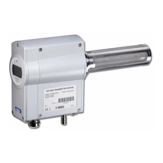
Vaisala Spectracap OMT355 User Manual (165 pages)
Oxygen Transmitter
Brand:
Vaisala
| Category:
Transmitter
| Size: 2.79 MB
Table of Contents
Table of Contents
3
Chapter 1 General Information
13
About this Manual
13
General Safety Considerations
13
Feedback
14
Product Related Safety Precautions
14
ESD Protection
15
Recycling
15
Regulatory Compliances
16
Trademarks
16
License Agreement
16
Warranty
17
Chapter 2 Product Overview
19
Introduction to Vaisala SPECTRACAP® Oxygen
19
Transmitter OMT355
19
Oxygen Measurement Range
19
OMT355 for In-Line and Sampling Cell Mounting
20
Figure 1 Flange Mounted Vaisala SPECTRACAP Oxygen Transmitter OMT355
21
Figure 2 OMT355 with Sampling Cell
21
Ambient Gas Measurement Version of OMT355
22
Figure 3 OMT355 for Ambient Gas Measurement
22
Functional Description
23
Chapter 3 Functional Description
23
Measurement Principle and Sensor Technology
23
Figure 4 O2 Absorption Spectrum Around the 760 Nm Near Infrared
24
Figure 5 Adjacent O2 Absorption Lines and Laser Emission Peak
24
Region
24
Construction of OMT355 Probe
25
Figure 6 Schematic of Probe Design
25
Eye Safety
26
Figure 7 OMT355 Laser Eye Safety
26
Chapter 4 Installation
27
Selecting Location
27
Chemical Tolerance
27
OMT355 Dimensions
28
Figure 8 OMT355 Dimensions in MM
28
Table 1 Chemical Tolerance of Sealing Materials
28
Temperature Conditions of Installation Location
29
Powerful Light Sources Near the Oxygen Measurement
29
Probe
29
Maximum Allowed Installation Angle
30
Mounting Options
31
Process Conditions in Regard to Mounting Options
31
Figure 9 Installation Angle Limitations in High Humidities
31
Table 2 Process Conditions and Mounting Options
32
Flange Mounted for In-Line Process Gas Measurement
33
Figure 10 OMT355 Transmitter with Flange Adapter
33
Filter Recommendation
33
Suitable Process Flanges
33
Mounting with Flange Adapter
34
Figure 11 Dimensions, OMT 355 Flange Mounted
35
Figure 12 OMT355 Transmitter with Sampling Cell
36
Filter Recommendation
36
Mounting with Sampling Cell
36
Figure 13 Sample Gas Treatment System
37
Installation Instructions for Swagelok Tube Fittings
38
Mounting with Wall Mounting Bracket
38
Tubing Instructions
38
Figure 14 Swagelok Tube Fitting Instructions
39
Sampling Cell Instructions
39
Figure 15 Detaching Sampling Cell
40
Figure 16 Dimensions, OMT355 with Sampling Cell
40
Mounting OMT355 for Ambient Gas Measurement
41
Figure 17 OMT355 for Ambient Gas Measurement with Wall Mounting
41
Mounting Instructions
41
Setup
41
Figure 18 OMT355 Wall Mounted
42
Connections
43
Figure 19 Dimensions and Drilling Holes, Wall Mounting Bracket (Right)
43
Signal and Power Supply Wiring
43
And Flange Adapter (Left)
43
Figure 20 Connections/Local Interface Layout
44
Connecting OMT355 with Optional 8-Pin Connector
46
Figure 21 Optional 8-Pin Connector
46
Table 3 8-Pin Connector Terminals
46
Chapter 5 Operation
47
Device Interfaces
47
Power Supply
47
Keypad, Display and Leds
47
Service Interface
48
Installing the Driver for the USB Cable
48
Analog Output
49
Customer Interface
49
Relay
49
Local Interface (Keypad and Display)
50
Features
50
Figure 22 OMT355 Display Layout
50
Display Modes
51
Start-Up
51
Error Condition
52
Normal Operation
52
Warning
52
Service Interface
53
Customer Interface
53
Functions
54
General Instructions for Using Functions
54
Menu Structure
54
Serial Commands
58
Table 4 Meaning of the Command Line Elements
58
Table 5 OMT355 Default Serial Communication Settings
58
List of Serial Commands
59
Table 6 List of Serial Commands Without Password
59
Table 7 List of Additional Serial Commands with Password Given
59
Outputting Measurement Results
60
Start Continuous Output Command (R)
60
Send Measurement Results Command (SEND)
61
Show/Set Continuous Output Interval Command (INTV)
61
Stop Continuous Output Command (S)
61
>Smode
62
Show/Set Serial Communications Mode Command
62
Show/Set Serial Communications Mode for Line 2 Command (SMODE2)
63
Show/Set Serial Communications Settings Command
63
>Seri
64
Show/Set Serial Communication Settings for Line 2 Command (SERI2)
64
Show Serial Line 1 Status Command (SCI1)
65
Show Serial Line 2 Status Command (SCI2)
65
Show Measurement Status Command (MEA)
66
Oxygen Statistics Display Function
66
Temperature Statistics Display Function
67
Formatting Measurement Results
67
Set Output Format Command (FORM)
67
Table 8 Format String Abbreviations and Quantities
68
Table 9 Format String Modifiers
68
Show/Set Date Command (DATE)
69
Show/Set Time Command (TIME)
70
Networking Operation
71
Show/Set Device Address Command (ADDR)
71
Open Communications Line Command (OPEN)
71
Close Serial Line in Poll Mode Command (CLOSE)
72
Set Echoing Mode Command (ECHO)
72
Accessing Service Level Commands
73
Issue Password Command (PASS)
73
Issue Password Function (Pas)
74
Analog Output Calibration
75
Calibrate Analog Output Command (ICAL)
75
Analog Output Scaling and Settings
75
Scale Analog Output Function (Ascl)
75
Show/Set Output Parameters Command (OUT_PARAMS)
77
Analog Output Testing
77
Set Test Current to Analog Output Command (ITEST)
77
Test Analog Output Function (Aou)
78
Relay Operation
79
Show/Set Relay Operating Mode Command
79
Show/Set Relay Trigger Points Command (RSEL)
80
Test Alarm Relay Function (Ala)
80
Device Information and Other General Commands
81
Show Information about the Device Command (?)
81
Show Information about the Device Overriding POLL Mode Command (??)
81
Show Measuring Parameters Command (CALCS)
82
Show Calibration Information (CINFO)
82
Show Display Board Status Command (DB)
83
List Commands Command (HELP)
83
Show Laser Temperature Controller Status Command
84
>Ltc
84
Show Output Status Command (OUT)
84
Show All Modifiable Parameter Values (PARAM)
85
Measure Signal Level Command (SIL)
86
Signal Level Display Function (Sil)
86
Show Statistical Information Command (STATS)
87
Show Status of Subfunctions Command (STATUS)
87
Show Product Name and Software Version Command
88
>Vers
88
Memory Handling
88
Save Parameters Command (SAVE)
88
Resetting the Transmitter
89
Reset Command (RESET)
89
Reset Function (Off)
89
Chapter 6 Setting Environmental Parameters
91
Environmental Parameter Compensations
91
Operating Temperature
92
Operating Pressure
92
Figure 23 Effect of Process Pressure Compensation
93
(Pres)
94
Show/Set Pressure for Compensation Command
94
Set (Average) Process Pressure Function (App)
95
Set Pressure for Compensation Command (XPRES)
95
Background Gas Effects
96
General Information about Background Gas Effects
96
Water Content of Background Gas
97
Table 10 Conversion Table from T and RH to Absolute Humidity and the Effect of Humidity on Transmitter Reading
98
Set Water Content for Compensation Command (H2O)
99
CO2 Concentration of Background Gas
100
Set (Average) Water Content Function (H2O)
100
Set (Average) Carbon Dioxide Content Function (CO2)
101
Set Carbon Dioxide Content for Compensation Command (CO2)
101
Setting Several/All Environmental Parameters with Single Command (ENV)
102
Chapter 7 Calibration and Adjustment (In-Line and Sampling Cell Versions of Omt355)
103
Hardware Arrangements for Calibration and Adjustment
104
Getting Started
104
Gas Feed Setup for Calibration and Adjustment
104
Using Ambient Air
104
Calibration or Adjustment in Process
105
Figure 24 Attaching OMT355 Probe into Calibration Chamber
105
Setup
105
Using Bottled Gas and Calibration Chamber
105
Connecting the Gas
106
Connections and Systems
106
Preparations for Adjustment
106
Adjusting Gas Flow
107
Figure 25 Flow Rate Vs. Pressure, Back Pressure Valve Swagelok
108
Information on Calibration Gases
108
Ss-Chsm2-Kz-25
108
Calibration
109
Using Ambient Air
109
Using Calibration Gases
110
Calibration Procedures
110
Figure 26 Oxygen Readings in Relative Humidity
110
Lock Outputs for Calibration Command (ADJUST)
110
Calibration Check Function (Cal.C)
111
Adjustment
111
Possible Adjustments
112
One-Point Adjustment Using Serial Line
112
Make One-Point Adjustment Command (COXY1)
112
One-Point Adjustment Procedure Using Serial Line
113
One-Point Adjustment Using Local Interface
115
One-Point Adjustment Function (CAL1)
115
Interface
116
One-Point Adjustment Procedure Using Local
116
Two-Point Adjustment Using Serial Line
117
Make Two-Point Adjustment Command (COXY2)
117
Two-Point Adjustment Procedure Using Serial Line
118
Two-Point Adjustment Using Local Interface
121
Interface
121
Two-Point Adjustment Function (CAL2)
121
Two-Point Adjustment Procedure Using Local
121
Restoring Factory Calibration
123
Restore Factory Calibration Command (FCRESTORE)
123
Restore Factory Calibration Function (Fac)
123
Chapter 8 Calibration and Adjustment (Ambient Gas Measurement Version of Omt355)
125
Hardware Arrangements for Calibration and Adjustment
126
Getting Started
126
Gas Feed Setup for Calibration and Adjustment
127
Using Ambient Air
127
Using Bottled Calibration Adjustment Gas
127
Calibration
128
Using Ambient Air
128
Figure 27 Attaching OMT355 Probe into Sample Cell
128
Using Calibration Gas
129
Figure 28 Oxygen Readings in Alternating Humidity
129
Figure 29 Calibration Gas O2 Concentration Readings for Ambient Gas Measurement Version of OMT355
130
Information on Calibration Gases
131
Calibration Procedures
131
Lock Outputs for Calibration Command (ADJUST)
131
Calibration Check Function (Cal.C)
132
Adjustment
132
Possible Adjustments for Ambient Measurement Version
133
One-Point Adjustment Using Serial Line
134
One-Point Adjustment Command (COXY1)
134
One-Point Adjustment Procedure Using Serial Line
135
One-Point Adjustment Using Local Interface
137
Interface
137
One-Point Adjustment Function (CAL1)
137
One-Point Adjustment Procedure Using Local
137
Restoring Factory Calibration
138
Restore Factory Calibration Command (FCRESTORE)
138
Restore Factory Calibration Function (Fac)
139
Chapter 9 Maintenance
141
Field Maintenance
141
Cleaning the Optics
141
Cleaning the Mirror
142
Figure 30 Location of Mirror in Oxygen Measurement Probe
142
Using Solvents to Clean the Optics
142
Cleaning the Lens
143
Figure 31 Location of Lens in Oxygen Measurement Probe
143
Replacing Consumables
144
OMT355 Filters
144
Filter Change
144
Cleaning and Changing the Stainless Steel Mesh
144
Figure 32 Stainless Steel Mesh and PTFE Filters
144
Filter
144
Changing the PTFE Filter
145
Spare Parts and Accessories
146
Table 11 Available Spare Parts and Accessories
146
Chapter 10 Troubleshooting
147
Operation Errors
147
Self-Test
147
Error Detection During Operation
148
Error Control and Error Categories
149
Fatal Errors
149
Nonfatal Errors
150
Table 12 Actions When Fatal Error Has Been Detected
150
Table 13 Actions When Nonfatal Error Has Been Detected
150
Table 14 Actions When Warning Has Been Detected
150
Warnings
150
Emergency Shutdown State
151
Show Error Control Status (ERR)
151
Table 15 Emergency Shutdown Actions
151
Show Error Log (ERRL)
152
Show Detected Errors (ERRS)
152
Show Error Table (ERRT)
152
Error Display
153
Error Table
153
Table 16 Error Table
153
Technical Support
154
Return Instructions
154
Vaisala Service Centers
155
Chapter 11 Technical Data
157
Specifications
157
Table 17 Performance
157
Table 18 Background Gas Effect
158
Table 19 Operating Environment
158
Table 20 Inputs and Outputs
158
Table 21 Approvals and Fulfilled Standards
159
Table 22 Dimensions and Mechanics
160
Table 23 Options and Accessories
160
Appendix A
161
Flange Preparation Instructions
161
Appendix B
163
Humidity Conversion Table
163
Advertisement
Advertisement
Related Products
Vaisala Spectracap OMT364
Vaisala Optimus OPT100
Vaisala 19164ZZ
Vaisala 25917ZZ
Vaisala AQT530
Vaisala CARBOCAP GMT220 SERIES
Vaisala CARBOCAP GMT221
Vaisala CARBOCAP GMT222
Vaisala CARBOCAP GMW84
Vaisala CARBOCAP GMW84S
Vaisala Categories
Transmitter
Measuring Instruments
Accessories
Test Equipment
Weather Station
More Vaisala Manuals
Login
Sign In
OR
Sign in with Facebook
Sign in with Google
Upload manual
Upload from disk
Upload from URL