
Vaisala PTU300 Manuals
Manuals and User Guides for Vaisala PTU300. We have 3 Vaisala PTU300 manuals available for free PDF download: User Manual, Manual

Vaisala PTU300 User Manual (218 pages)
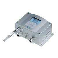
Combined Pressure, Humidity and Temperature Transmitter
Brand: Vaisala
|
Category: Transmitter
|
Size: 2.61 MB
Table of Contents
-
Chapter 2
13-
Safety
15 -
Recycling
16 -
Trademarks
18 -
Warranty
19
-
-
-
-
-
-
-
-
-
-
Send99
-
-
-
Open100
-
Close100
-
-
FTIME and FDATE101
-
-
-
General Settings
102-
-
Date and Time106
-
NMEA Data Format107
-
GPS Commands108
-
-
-
-
Data Recording
123 -
-
-
Relay Setpoints133
-
Hysteresis135
-
-
-
Rtest141
-
-
Sensor Functions
141 -
Chapter 5 Modbus
149-
Disabling MODBUS
157
-
-
-
Specifications
181-
Performance181
-
-
-
-
-
-
Function Codes
209 -
Register Map
210-
Data Encoding210
-
-
Advertisement
Vaisala PTU300 User Manual (190 pages)
Combined Pressure, Humidity and Temperature Transmitter
Brand: Vaisala
|
Category: Transmitter
|
Size: 3.05 MB
Table of Contents
-
-
Recycling
16 -
Trademarks
17 -
Warranty
18
-
-
-
-
-
-
-
-
-
-
GPS Commands100
-
-
-
-
PRES and XPRES102
-
Pfix103
-
Pstab103
-
-
-
Data Recording
112 -
-
-
Relay Setpoints122
-
Hysteresis123
-
-
-
Rtest129
-
-
Sensor Functions
133
-
-
-
Specifications
161-
Relay Module169
-
-
-
Appendix B
185

Vaisala PTU300 Manual (3 pages)
Industrial Transmitters
Brand: Vaisala
|
Category: Transmitter
|
Size: 2.07 MB
Advertisement