Sign In
Upload
Manuals
Brands
Vaisala Manuals
Transmitter
MHT410
Vaisala MHT410 Manuals
Manuals and User Guides for Vaisala MHT410. We have
1
Vaisala MHT410 manual available for free PDF download: User Manual
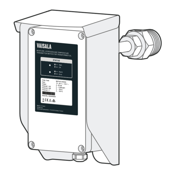
Vaisala MHT410 User Manual (116 pages)
Vaisala Moisture, Hydrogen and Temperature Transmitter for Transformer Oil
Brand:
Vaisala
| Category:
Transmitter
| Size: 4.36 MB
Table of Contents
Table of Contents
3
1 Safety
9
ESD Protection
10
2 About this Document
11
Documentation Conventions
11
Table 2 Related Manuals
11
Regulatory Compliances
12
Trademarks
12
3 Product Overview
13
Main Features
13
Product Parts and Package Contents
14
Measurement Parameters and Units
16
Data Logging
17
Status Leds
17
4 Installation
19
Planning the Installation
19
Recommended Installation Locations
19
Figure 1 Recommended Installation Locations
20
Mechanical Installation
21
Electrical Installation
28
Loop-Powered Display
32
Figure 2 Loop-Powered Display 242003
32
Wiring the Loop-Powered Display
33
Checklist after Installation
34
Oil Fittings Check after Installation
34
Removing the Transmitter
34
Re-Installing the Transmitter in New Location
35
5 Analog Output
38
Analog Output Overrange Behavior
38
Table 3 Analog Output Values in Different Transmitter Statuses
38
Figure 3 Analog Output Overrange Behavior
39
6 Modbus
40
Overview of Modbus Protocol Support
40
7 Vaisala Industrial Protocol
41
Table 4 Default Serial Interface Settings
41
Connecting Via Service Port
42
Installing the Driver for the USB Service Cable
42
Connecting USB Cable
43
Configuring Terminal Application Settings
43
Table 5 Service Port Serial Interface Settings
44
Serial Commands Summary
45
Table 11
45
Table 6 Serial Commands
45
Device Information and Status Commands
47
Table 7 ? Command
47
Table 8 Alarm Command
48
Table 9 Errlog Command
49
Table 10 Errs Command
50
Table 11 Help Command
51
Table 12 System Command
51
Table 13 Time Command
52
Table 14 Vers Command
52
Serial Line Output and Communication Commands
53
Measurement Output Commands
53
Table 15 Intv Command
53
Table 16 Log Command
53
Table 17 R Command
56
Table 18 Send Command
56
Measurement Output Format Commands
57
Table 19 Form Command
57
Table 20 Output Parameters for Form Command
58
Table 21 Modifiers for Form Command
59
Serial Line Communication Commands
60
Table 22 Unit Command
60
Table 23 Addr Command
60
Table 24 Close Command
61
Table 25 Open Command
61
Table 26 Sdelay Command
61
Table 27 Seri Command
62
Table 28 Smode Command
63
Analog Output Commands
64
Table 29 Aerr Command
64
Table 30 Aover Command
64
Figure 4 Analog Output Overrange Behavior
65
Table 31 Asel Command
65
Table 32 Atest Command
67
Calibration and Adjustment Commands
68
Table 33 Cdate Command
68
Table 34 Ctext Command
68
Other Commands
69
Table 35 H2 da and H2 Db Commands
69
Table 36 Dnp3 Addr Command
69
Table 37 Filt Command
70
Table 38 Frestore Command
70
Table 39 Reset Command
71
Table 40 H2 Is Command
71
8 DNP3 Protocol
72
Connecting Via Service Port
72
Table 41 Default Communication Settings
72
Connecting USB Cable
73
Installing the Driver for the USB Service Cable
73
Configuring Terminal Application Settings
74
Taking DNP3 Protocol into Use
75
Table 42 Service Port Serial Interface Settings
75
9 MI70 Hand-Held Indicator
77
MI70 Indicator Overview
77
MI70 Indicator Parts
77
Figure 5 MI70 Indicator Parts
77
Basic Display
78
Graphical Display
78
Figure 6 MI70 Basic Display
78
Main Menu
79
Installing and Recharging MI70 Batteries
79
Connecting MI70 to Service Port
79
Holding and Saving the Display
80
Recording Data
80
Starting and Stopping the Recording
81
Viewing Recorded Data
82
Clearing Data Memory
82
Comparing Readings with MM70 Probe
82
Changing the Rechargeable Battery Pack
83
Figure 7 Example of MI70 Display with MHT410 in Port I and MM70 Probe in Port II. Shown Parameters: Aw (I), Aw (II), Δ Aw
83
10 Calibration and Adjustment
85
H 2 Calibration and Adjustment
85
Taking DGA Sample and Saving Current H2 Reading
85
Entering DGA H Reading to Transmitter
86
RS & T Calibration and Adjustment
88
11 Troubleshooting
89
Error States
89
Table 43 Possible Error Messages Via Vaisala Industrial Protocol
89
Changing Bleed Screw
90
12 Technical Data
92
Table 44 Measurement Performance
92
Table 45 Operating Environment
93
Table 46 Inputs and Outputs
93
Table 47 Mechanical Specifications
94
Table 48 Compliance
94
Table 49 Display with Relays (External Option)
95
Spare Parts and Accessories
96
Table 50 Spare Parts and Accessories
96
Dimensions
97
Wiring Diagrams
98
Figure 8 Wiring Option 1: Wiring with Four Power Supplies
98
Table 51 Vaisala Cable CBL210392-5M Wire Colors (When Pre-Wired)
98
Figure 9 Wiring Option 2: Wiring with Two Power Supplies
99
Figure 10 Wiring Option 3: Wiring with One Power Supply. Non
99
Common Loop Powering and Galvanic Isolation for Analog Outputs
99
Recycling
100
Figure 11 Wiring Option 4: Wiring with One Power Supply
100
Figure 12 Materials for Recycling
101
Table 52 Materials for Recycling
102
Appendix A: Operating Principle
103
Figure 13 Measuring Hydrogen and Moisture in Oil with MHT410
103
Table 53 Optimal Sensor Positions
103
Method Used for Measuring Moisture in Oil
104
Transformer Oil
104
Figure 14 Water Solubility of Transformer Oils Versus Temperature
105
Appendix B: Modbus Reference
106
Function Codes
106
Data Encoding
106
32-Bit Floating Point or Integer Format
106
Table 54 Modbus Function Codes
106
16-Bit Integer Format
107
Register Map
107
Modbus Registers
107
Table 55 16-Bit Signed Integer Format Details
107
Table 56 Modbus Register Blocks
107
Measurement Data Registers
108
Table 57 Modbus Measurement Data Registers (Read-Only)
108
B.4.2 Status Registers
109
Status Registers
109
Table 58 Modbus Status Registers (Read-Only)
109
Table 59 Modbus Device Status Bits
109
Device Identification Objects
110
Table 60 Device Identification Objects
110
Exception Responses
111
Table 61 Modbus Exception Responses
111
B.6 Exception Responses
111
Appendix C: Moisture Ppm Calculation for Transformer Oils
112
Calculation Model with Average Coefficients
112
Calculation Model with Oil-Specific Coefficients
112
Warranty
113
Technical Support
113
Advertisement
Advertisement
Related Products
Vaisala HUMICAP MMT330
Vaisala HUMICAP MMT310
Vaisala HUMICAP MMT162
Vaisala MW12
Vaisala MAWS201
Vaisala MAWS101
Vaisala MGP261
Vaisala M212551EN-B
Vaisala MWP312
Vaisala MWF210
Vaisala Categories
Transmitter
Measuring Instruments
Accessories
Test Equipment
Weather Station
More Vaisala Manuals
Login
Sign In
OR
Sign in with Facebook
Sign in with Google
Upload manual
Upload from disk
Upload from URL