Sign In
Upload
Manuals
Brands
Vaisala Manuals
Temperature Controller
HUMICAP HMW92
Vaisala HUMICAP HMW92 Manuals
Manuals and User Guides for Vaisala HUMICAP HMW92. We have
2
Vaisala HUMICAP HMW92 manuals available for free PDF download: User Manual
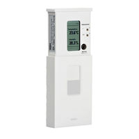
Vaisala HUMICAP HMW92 User Manual (110 pages)
Humidity and Temperature Transmitter
Brand:
Vaisala
| Category:
Transmitter
| Size: 1.7 MB
Table of Contents
Table of Contents
3
Vaisala
5
Chapter 1 General Information
9
Chapter 2
9
Version Information
10
Related Manuals
10
Documentation Conventions
10
Table 1 Manual Revisions
10
Table 2 Related Manuals
10
About this Manual
9
Contents of this Manual
9
Safety
11
ESD Protection
11
Recycling
11
Regulatory Compliances
12
Patent Notice
12
Trademarks
12
Software License
12
Warranty
13
Chapter 2 Product Overview
15
Introduction to HMW90 Series
15
Figure 1 HMW90 Series Transmitters
15
HMW90 Series Transmitters
16
Table 3 HMW90 Series Transmitters
16
Output Parameters Explained
17
Table 4 Parameters Supported by HMW90 Series
17
Transmitter Parts
18
Figure 2 Transmitter Parts - Outside
18
Figure 3 Opening the Transmitter
19
Figure 4 Transmitter Parts - Inside (Analog Output Models)
20
Figure 5 Transmitter Parts - Inside (Digital Output Models)
21
Chapter 3 Installation
23
Configuration before Installation
23
Configuration of Analog Output Models
23
DIP Switches of Analog Output Models
24
Figure 6 DIP Switch Settings of Analog Output Models
24
Relay Configuration in DIP Mode
25
Table 5 Rotary Switch and Relay Setpoint
25
Figure 7 Relay High in DIP Mode (HMW93)
26
Figure 8 Relay Low in DIP Mode (HMW93)
26
Configuration of Digital Output Models
27
DIP Switches of Digital Output Models
28
Figure 9 DIP Switch Settings of Digital Output Models
28
Addressing with Bacnet Protocol
29
Addressing with Modbus Protocol
29
Figure 10 Example of Transmitter Addressing
29
Selecting Location
30
Figure 11 Selecting Transmitter Location
30
Wiring
31
Wiring HMW92
31
Figure 12 Wiring HMW92
31
Figure 13 Three-Wire Wiring for HMW92
31
Wiring HMW93
32
Figure 14 Wiring HMW93
32
Figure 15 Three-Wire Wiring for HMW93
32
Wiring TMW92
33
Wiring TMW93
33
Figure 16 Wiring TMW92
33
Figure 17 Wiring TMW93
33
Figure 18 Three-Wire Wiring for TMW93
33
Connecting a Common AC Power Supply to Several Transmitters
34
Figure 19 Connecting a Common AC Power Supply (HMW93)
34
Wiring HMW95
35
Connecting Several Transmitters on same
35
Line (HMW95)
35
Figure 20 Wiring HMW95
35
Figure 21 Several Transmitters on same RS-485 Line
35
Chapter 4 Operation
37
Display
37
Startup Screens
37
Figure 22 HMW93 Startup Screens
37
Measurement Screen
38
Figure 23 HMW93 Measurement Screen - Normal Operation
38
Figure 24 HMW93 Measurement Screen - Problem with
38
Indicators on the Display
39
Service Port
39
Connecting with an MI70 Indicator
39
Connecting with a PC
40
Installing the Driver for the USB Service Cable
40
Terminal Application Settings
41
Table 6 Serial Interface Settings
41
Figure 25 Putty Terminal Application
42
List of Serial Commands
43
Table 7 Basic Serial Commands
43
Table 8 Advanced Serial Commands
43
Transmitter Information
44
Show Transmitter Information
44
Show Transmitter Firmware Version
44
Show Transmitter Serial Number
44
Show Transmitter Status
45
Show Measured Parameters
47
Show Command Help
47
Show Command List
48
Measurement Settings
48
Set Environmental Parameters
48
Select Units
49
Analog Output Settings
49
Set Analog Output Mode
49
Set Analog Output Scaling
50
Set Output Clipping and Error Limit
51
Display Settings
52
Select Parameters to Display
52
Serial Line Output Commands
53
Start Measurement Output
53
Stop Measurement Output
53
Output a Reading Once
54
Set Output Interval
54
Set Output Format
55
Serial Line Settings
56
Set Remote Echo
56
Table 9 FORM Command Parameters
56
Table 10 FORM Command Modifiers
56
Set Serial Line Response Time
57
Relay Configuration in Custom Mode
57
Set Relay Mode
57
Set Relay Parameter and Limits
58
Relay Configuration Examples
59
Figure 26 Relay Hi_Active in Custom Mode (HMW93)
59
Figure 27 Relay Lo_Active in Custom Mode (HMW93)
59
Calibration and Adjustment Commands
60
Adjust Humidity Measurement
60
Show Current RH Adjustment
60
1-Point Adjustment of RH Measurement
61
Clear User Adjustment of RH Measurement
62
Adjust Temperature Measurement
62
Show Current T Adjustment
62
1-Point Adjustment of T Measurement
62
Clear User Adjustment of T Measurement
63
Enter Calibration and Adjustment Information
63
Testing Commands
64
Test Analog Outputs
64
Test Relay Operation
65
Other Commands
65
Enable Advanced Serial Commands
65
Reset Transmitter
66
Set Bacnet Parameters
66
Chapter 5 Maintenance
69
Periodic Maintenance
69
Cleaning
69
Calibration and Adjustment
70
Adjustment Using Display and Trimmers
71
Figure 28 Trimmer Centering Screen
71
Figure 29 Trimmer Centering Screen
71
Adjustment Using an HM70
72
Adjustment Using a PC
73
Repair Maintenance
74
Replacing the Measurement Module
74
Figure 30 HTM10 and TM10 Modules
74
Figure 31 Replacing the HTM10 Module (HMW93)
75
Chapter 6 Troubleshooting
77
Problem Situations
77
Table 11 Troubleshooting Table
77
Error Messages
78
Error Messages on the Display
78
Error Messages on the Serial Line
78
View Currently Active Errors
78
Table 12 Error Messages on the Display
78
View Error Table
79
Table 13 Error Messages on the Serial Line
79
Error State
80
Reverting to Factory Settings
81
Reverting to Factory Settings Using DIP Switches
81
Figure 32 DIP Switches in Factory Reset Position
81
Reverting to Factory Settings Using Service Port
82
Figure 33 DIP Switches in Factory Reset Position (HMW95)
82
Technical Support
83
Product Returns
83
Chapter 7 Technical Data
85
Specifications
85
Table 14 Performance
85
Table 15 Operating Environment
85
Table 16 Inputs and Outputs
86
Table 17 Mechanics
86
Spare Parts and Accessories
87
Table 18 HMW90 Series Spare Parts and Accessories
87
Dimensions in MM
88
Figure 34 HMW90 Series Dimensions
88
Figure 35 Dimensions of the Mounting Base
88
Appendix Abacnet Reference
89
Bacnet Protocol Implementation Conformance Statement
89
Device Object
92
Table 19 Device Object Properties
92
Object_Identifier
93
Object_Name
93
System_Status
93
Protocol_Services
94
Database_Revision
94
Relative Humidity Object
94
Table 20 Relative Humidity Object Properties
94
Status Flags
95
Reliability
95
Event State
95
Out of Service
95
Table 21 Status Flags
95
Table 22 Reliability
95
Table 23 Event State
95
Temperature Object
96
Units
96
Status Flags
96
Table 24 Temperature Object Properties
96
Table 25 Status Flags
96
Reliability
97
Event State
97
Out of Service
97
Table 26 Reliability
97
Table 27 Event State
97
Calculated Humidity Objects
98
Table 28 Calculated Humidity Objects
98
Table 29 Calculated Humidity Object Properties
98
Event State
99
Out of Service
99
Reliability
99
Status Flags
99
Table 30 Status Flags
99
Table 31 Reliability
99
Table 32 Event State
99
Event State
100
Operation Pressure Object
100
Out of Service
100
Present Value
100
Status Flags
100
Table 33 Operation Pressure Object Properties
100
Table 34 Status Flags
100
Operation Altitude Object
101
Present Value
101
Units
101
Status Flags
101
Event State
101
Out of Service
101
Table 35 Operation Altitude Object Parameters
101
Table 36 Status Flags
101
Bibbs Supported
102
Table 37 Bacnet Smart Sensor Bibbs Support
102
Application Services Supported
103
Table 38 Bacnet Standard Application Services Support
103
Appendix Bmodbus Reference
105
Function Codes
105
Table 39 Supported Function Codes
105
Register Map
106
Data Encoding
106
32-Bit Floating Point Format
106
Table 40 HMW90 Modbus Register Blocks
106
16-Bit Integer Format
107
Measurement Data (Read-Only)
107
Table 41 16-Bit Signed Integer Format Details
107
Table 42 HMW90 Modbus Measurement Data Registers
107
Status Registers (Read-Only)
108
Configuration Registers
108
Table 43 HMW90 Modbus Status Registers
108
Table 44 HMW90 Modbus Configuration Parameter Registers
108
Device Identification Objects
109
Exception Responses
109
Table 45 HMW90 Modbus Device Identification
109
Table 46 HMW90 Modbus Exception Responses
109
Advertisement
Vaisala HUMICAP HMW92 User Manual (100 pages)
Brand:
Vaisala
| Category:
Temperature Controller
| Size: 1.96 MB
Table of Contents
Table of Contents
3
Chapter 1 General Information
9
About this Manual
9
Contents of this Manual
9
Version Information
10
Related Manuals
10
Documentation Conventions
10
Table 1 Manual Revisions
10
Table 2 Related Manuals
10
Safety
11
ESD Protection
11
Recycling
11
Regulatory Compliances
12
Trademarks
12
Software License
12
Warranty
12
Chapter 2 Product Overview
13
Introduction to HMW90 Series
13
Figure 1 HMW90 Series Transmitters
13
HMW90 Series Transmitters
14
Table 3 HMW90 Series Transmitters
14
Output Parameters Explained
15
Table 4 Parameters Supported by HMW90 Series
15
Transmitter Parts
16
Figure 2 Transmitter Parts - Outside
16
Figure 3 Opening the Transmitter
17
Figure 4 Transmitter Parts - Inside (Analog Output Models)
18
Figure 5 Transmitter Parts - Inside (Digital Output Models)
19
Decorative Cover Option
20
Figure 6 Decorative Cover
20
Chapter 3 Installation
21
Configuration before Installation
21
Configuration of Analog Output Models
21
DIP Switches of Analog Output Models
22
Figure 7 DIP Switch Settings of Analog Output Models
22
Relay Configuration in DIP Mode
23
Table 5 Rotary Switch and Relay Setpoint
23
Figure 8 Relay High in DIP Mode (HMW93)
24
Figure 9 Relay Low in DIP Mode (HMW93)
24
Changing between DIP and Custom Configuration
25
Configuration of Digital Output Models
25
DIP Switches of Digital Output Models
26
Figure 10 DIP Switch Settings of Digital Output Models
26
Addressing with Bacnet Protocol
27
Addressing with Modbus Protocol
27
Figure 11 Example of Transmitter Addressing
27
Selecting Location
28
Figure 12 Selecting Transmitter Location
28
Installing the Mounting Base
29
Wiring
29
Figure 13 Installing the Mounting Base
29
Figure 14 Wiring from Behind (Recommended)
30
Figure 15 Wiring from above
30
Figure 16 Wiring HMW92
31
Figure 17 Three-Wire Wiring for HMW92
31
Wiring HMW92
31
Figure 18 Wiring HMW93
32
Figure 19 Three-Wire Wiring for HMW93
32
Wiring HMW93
32
Figure 20 Wiring TMW92
33
Figure 21 Wiring TMW93
33
Figure 22 Three-Wire Wiring for TMW93
33
Wiring TMW92
33
Wiring TMW93
33
Connecting Several Transmitters on same
34
Figure 23 Wiring HMW95
34
Figure 24 Several Transmitters on same RS-485 Line
34
Line (HMW95)
34
Wiring HMW95
34
Connecting a Common AC Power Supply to Several Transmitters
35
Figure 25 Connecting a Common AC Power Supply
35
Chapter 4 Operation
36
Display
36
Startup Screens
36
Figure 26 HMW93 Startup Screens
36
Measurement Screen
37
Figure 27 HMW93 Measurement Screen - Normal Operation
37
Figure 28 HMW93 Measurement Screen - Problem with Measurement
37
Indicators on the Display
38
Service Port
38
Connecting with an MI70 Indicator
38
Connecting with a Computer
39
Installing the Driver for the USB Service Cable
39
Table 6 Serial Interface Settings
40
Terminal Application Settings
40
Figure 29 Putty Terminal Application
41
List of Serial Commands
42
Table 7 Basic Serial Commands
42
Table 8 Advanced Serial Commands
42
Transmitter Information
43
Show Transmitter Information
43
Show Transmitter Firmware Version
43
Show Transmitter Serial Number
43
Show Transmitter Status
44
Show Measured Parameters
46
Show Command Help
46
Show Command List
47
Measurement Settings
47
Set Environmental Parameters
47
Select Units
48
Analog Output Settings
48
Set Analog Output Mode
48
Set Analog Output Scaling
49
Set Output Clipping and Error Limit
50
Display Settings
51
Select Parameters to Display
51
Serial Line Output Commands
52
Start Measurement Output
52
Stop Measurement Output
52
Output a Reading Once
53
Set Output Interval
53
Set Output Format
54
Serial Line Settings
55
Set Remote Echo
55
Table 9 FORM Command Parameters
55
Table 10 FORM Command Modifiers
55
Set Serial Line Turnaround Delay
56
Relay Configuration in Custom Mode
56
Set Relay Mode
56
Set Relay Parameter and Limits
57
Relay Configuration Examples
58
Figure 30 Relay Hi_Active in Custom Mode (HMW93)
58
Figure 31 Relay Lo_Active in Custom Mode (HMW93)
58
Calibration and Adjustment Commands
59
Adjust Humidity Measurement
59
Show Current RH Adjustment
59
1-Point Adjustment of RH Measurement
60
Clear User Adjustment of RH Measurement
61
Adjust Temperature Measurement
61
1-Point Adjustment of T Measurement
61
Show Current T Adjustment
61
Clear User Adjustment of T Measurement
62
Enter Calibration and Adjustment Information
62
Testing Commands
63
Test Analog Outputs
63
Test Relay Operation
64
Other Commands
64
Enable Advanced Serial Commands
64
Reset Transmitter
64
Set Bacnet Parameters
65
Chapter 5 Maintenance
67
Periodic Maintenance
67
Cleaning
67
Calibration and Adjustment
67
Adjustment Using Display and Trimmers
68
Figure 32 Trimmer Centering Screen
68
Adjustment Using an HM70
69
Figure 33 Trimmer Centering Screen
69
Adjustment Using a Computer
70
Repair Maintenance
71
Replacing the Measurement Module
71
Figure 34 HTM10 and TM10 Modules
71
Figure 35 Replacing the HTM10 Module (HMW93)
72
Chapter 6 Troubleshooting
73
Problem Situations
73
Table 11 Troubleshooting Table
73
Error Messages
74
Table 12 Error Messages
74
View Currently Active Errors
75
View Error Table
75
Viewing Error Messages on Serial Line
75
Error State
76
Reverting to Factory Settings
77
Reverting to Factory Settings Using DIP Switches
77
Figure 36 DIP Switches in Factory Reset Position
77
Figure 37 DIP Switches in Factory Reset Position (HMW95)
78
Reverting to Factory Settings Using Service Port
79
Technical Support
79
Chapter 7 Technical Data
80
Specifications
80
Table 13 Performance
80
Table 14 Operating Environment
80
Table 15 Inputs and Outputs
81
Spare Parts and Accessories
82
Table 16 Mechanics
82
Table 17 HMW90 Series Spare Parts and Accessories
82
Dimensions in MM
83
Figure 38 HMW90 Series Dimensions
83
Figure 39 Dimensions of the Mounting Base
83
Appendix Abacnet Reference
84
Bacnet Protocol Implementation Conformance Statement
84
Device Object
87
Table 18 Device Object Properties
87
Relative Humidity Object
89
Table 19 Relative Humidity Object Properties
89
Table 20 Status Flags
89
Table 21 Reliability
89
Table 22 Event State
89
Table 31 Event State
89
Calculated Humidity Objects
90
Table 23 Calculated Humidity Objects
90
Table 24 Calculated Humidity Object Properties
90
Table 25 Status Flags
90
Table 26 Reliability
91
Table 27 Event State
91
Temperature Object
92
Table 28 Temperature Object Properties
92
Table 29 Status Flags
92
Table 30 Reliability
92
Operation Pressure Object
93
Table 32 Operation Pressure Object Properties
93
Table 33 Status Flags
93
Operation Altitude Object
94
Table 34 Operation Altitude Object Parameters
94
Table 35 Status Flags
94
Table 36 Bacnet Smart Sensor Bibbs Support
95
Bibbs Supported
95
Table 37 Bacnet Standard Application Services Support
96
Application Services Supported
96
Table 38 Modbus Functions Supported by HMW90
97
Table 39 HMW90 Modbus Measurement Data Registers
97
Appendix B
97
Table 40 HMW90 Modbus Status Registers (Read-Only)
98
Table 41 HMW90 Modbus Error Code Bits
98
Table 42 HMW90 Modbus Configuration Parameter Registers
98
Vaisala
99
Table 43 HMW90 Modbus Device Identification
99
Table 44 HMW90 Modbus Exception Responses
99
Modbus Reference
97
Advertisement
Related Products
Vaisala HUMICAP HMM212
Vaisala HMP35D
Vaisala HUMICAP HMW93
Vaisala HUMICAP HMW92D
Vaisala HUMICAP HMW93D
Vaisala HUMICAP HMW95
Vaisala HUMICAP HMW95D
Vaisala HMP 35A
Vaisala HUMICAP TMW92
Vaisala HUMICAP TMW93
Vaisala Categories
Transmitter
Measuring Instruments
Accessories
Test Equipment
Weather Station
More Vaisala Manuals
Login
Sign In
OR
Sign in with Facebook
Sign in with Google
Upload manual
Upload from disk
Upload from URL