Vaisala HUMICAP HMW90 SERIES Manuals
Manuals and User Guides for Vaisala HUMICAP HMW90 SERIES. We have 6 Vaisala HUMICAP HMW90 SERIES manuals available for free PDF download: Quick Manual, User Manual, Technical Reference Manual
Vaisala HUMICAP HMW90 SERIES User Manual (110 pages)
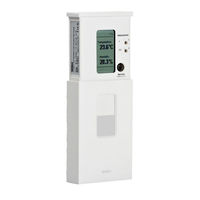
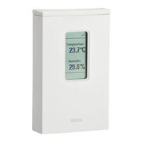
Humidity and Temperature Transmitter
Brand: Vaisala
|
Category: Transmitter
|
Size: 1.7 MB
Table of Contents
Advertisement
Vaisala HUMICAP HMW90 SERIES User Manual (100 pages)
Brand: Vaisala
|
Category: Temperature Controller
|
Size: 1.96 MB
Table of Contents

Vaisala HUMICAP HMW90 SERIES User Manual (66 pages)
HUMICAP Humidity and Temperature Transmitter
Brand: Vaisala
|
Category: Transmitter
|
Size: 1.48 MB
Table of Contents
Advertisement
Vaisala HUMICAP HMW90 SERIES Quick Manual (101 pages)
HMW90 Series, GMW90 Series Transmitters with Digital Output
Brand: Vaisala
|
Category: Transmitter
|
Size: 3.18 MB
Table of Contents

Vaisala HUMICAP HMW90 SERIES Quick Manual (118 pages)
Transmitters with Analog Output
Brand: Vaisala
|
Category: Transmitter
|
Size: 3.41 MB
Table of Contents

Vaisala HUMICAP HMW90 SERIES Technical Reference Manual (20 pages)
BACnet Protocol Information Conformance Statement
Brand: Vaisala
|
Category: Transmitter
|
Size: 0.34 MB