Sign In
Upload
Manuals
Brands
Vaisala Manuals
Transmitter
HUMICAP HMT330 SERIES
Vaisala HUMICAP HMT330 SERIES Manuals
Manuals and User Guides for Vaisala HUMICAP HMT330 SERIES. We have
4
Vaisala HUMICAP HMT330 SERIES manuals available for free PDF download: User Manual, Quick Reference Manual, Manual
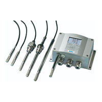
Vaisala HUMICAP HMT330 SERIES User Manual (206 pages)
Humidity and Temperature Transmitter
Brand:
Vaisala
| Category:
Transmitter
| Size: 2.45 MB
Table of Contents
Table of Contents
3
Vaisala
3
Vaisala
9
Chapter 1 General Information
13
About this Manual
13
Contents of this Manual
13
Chapter 2
13
Version Information
14
Documentation Conventions
14
Table 1 Manual Revisions
14
Safety
15
ESD Protection
15
Recycling
16
Regulatory Compliances
16
EU Declaration of Conformity
16
DNV Type Approval
17
Table 2 Application, Location Classes
17
Transmitters with LAN or WLAN Interface
17
Transmitters with WLAN Interface
18
Patent Notice
18
Trademarks
18
License Agreement
19
Warranty
19
Chapter 2 Product Overview
21
Introduction to HMT330
21
Table 3 Quantities Measured by HMT330
21
Table 4 Optional Quantities Measured by HMT330
21
Basic Features and Options
22
Figure 1 Transmitter Body
23
Structure of the Transmitter
23
Figure 2 Inside the Transmitter
24
Figure 3 HMT331 Fixed Probe
25
Figure 4 HMT331 Short Cable Probe
25
Probe Options
25
Figure 5 Probe Options
26
Warmed Probe HMT337
27
Chapter 3 Installation
29
Mounting the Housing
29
Standard Mounting Without Mounting Plate
29
Figure 6 Standard Mounting
29
Wall Mounting with Wall Mounting Kit
30
Figure 7 Mounting with Wall Mounting Kit
30
Figure 8 Dimensions of the Plastic Mounting Plate (MM/Inch)
30
Figure 9 Dimensions of the Probe Holder Plate (MM/Inch)
31
Mounting with DIN Rail Installation Kit
32
Pole Installation with Installation Kit for Pole or Pipeline
32
Figure 10 Mounting with the DIN Rail Installation Kit
32
Figure 11 Vertical Pole
32
Figure 12 Horizontal Pole
33
Figure 13 Mounting with Metal Wall Mounting Plate
33
Mounting Rain Shield with Installation Kit
34
Figure 14 Dimensions of the Metal Mounting Plate (MM/Inch)
34
Figure 15 Mounting the Rain Shield with the Installation Kit
34
Panel Mounting Frame
35
Figure 16 Panel Mounting Frame
35
Wiring
36
Cable Bushings
36
Figure 17 Panel Mounting Dimensions (MM/Inch)
36
Figure 18 Cable Bushings
36
Figure 19 Grounding the Screen of Electrical Cable
37
Grounding the Cables
37
Grounding the Transmitter Housing
38
Figure 20 Screw Terminal Block on Motherboard
39
Signal and Power Supply Wiring
39
Connections to a 24 VAC Power Supply
40
Figure 21 Connections to 24 VAC Power Supply
41
Probe Mounting
42
Figure 22 Measurement Error at 100 %RH
42
Figure 23 Horizontal Mounting of Probe
43
General Instructions for Probes with a Cable
43
Figure 24 Vertical Mounting of Probe
44
HMT333 for Ducts and Tight Spaces
45
HMT334 for High Pressure and Vacuum Applications
45
Figure 25 HMT344 Probe
46
Figure 26 Tightening the Nut
46
HMT335 for High Temperatures
47
Figure 27 Cleaning of Tightening Cone
47
HMT337 for High Humidity Applications
48
Temperature Probe (Optional)
48
HMT338 for Pressurized Pipelines
48
Figure 28 HMT338 Probe
49
Figure 29 Sealing of Fitting Body into Process
49
Table 5 HMT338 Probe Dimensions
49
Figure 30 Tightening the Clasp Nut
50
Tightening the Clasp Nut
50
Optional Modules
51
Power Supply Module
51
Installation
52
Warnings
53
Galvanic Isolation for Output
56
Third Analog Output
56
Figure 32 Galvanic Output Isolation Module
56
Figure 33 Third Analog Output
56
Figure 34 Third Analog Output Selection
57
Installation and Wiring
57
Relays
58
Installation and Wiring
58
Selecting the Activation State of the Relay
58
RS-422/485 Interface
59
Figure 35 Relay Module
59
Figure 36 RS-422/485 Module
60
Installation and Wiring
60
Table 6 Connecting the Twisted Pair Wires to the Screw Terminals
61
Figure 37 4-Wire RS-485 Bus
62
Table 7 4-Wire (Switch 3: On)
62
Figure 38 2-Wire RS-485 Bus
63
Table 8 2-Wire (Switch 3: Off)
63
LAN Interface
64
WLAN Interface
65
Figure 39 LAN Interface Module
65
Attaching the WLAN Antenna
66
Figure 40 WLAN Interface Module
66
Data Logger Module
67
Table 9 Observation Periods and Resolution
67
Figure 41 Data Logger Module
68
8-Pin Connector
69
Figure 42 Pinout of the Optional 8-Pin Connector
69
Table 10 Wiring of the Optional 8-Pin Connector
69
Chapter 4 Operation
71
Getting Started
71
Display/Keypad (Optional)
71
Basic Display
71
Graphic History
72
Figure 43 Basic Display
72
Figure 44 Graphical Display
72
Figure 45 Graphical Display with Data Logger
73
Table 11 Periods for Trend and Max/Min Calculations
73
Menus and Navigation
74
Figure 46 Main Menus
74
Table 12 Graph Information Messages in Cursor Mode
74
Changing the Language
75
Display Backlight Setting
75
Rounding Setting
75
Display Contrast Setting
76
Keypad Lock (Key Guard)
76
Menu PIN Lock
76
Factory Settings
77
Display Alarms
77
Configuring a Display Alarm
78
Figure 47 Alarm Limits Shown on Graph Screen
78
Figure 48 Display Alarm Active
78
Figure 49 Display Alarms
79
Figure 50 Modifying an Alarm Limit
79
MI70 Link Program for Data Handling
80
Serial Line Communication
81
Figure 51 Service Port Connector and User Port Terminal on Motherboard
81
User Port Connection
82
Figure 52 Connection Example between PC Serial Port and User Port
82
Table 13 Default Serial Communication Settings for the User Port
82
User Port Operating Modes
82
Service Port Connection
83
Connection Cables
83
Installing the Driver for the USB Cable
83
Using the Service Port
84
LAN Communication
84
Table 14 Communication Settings for the Service Port
84
IP Configuration
85
Table 15 IP Settings for the LAN and WLAN Interfaces
85
Figure 53 Network Interface Menu
86
Figure 54 IP Configuration Menu
86
Using Display/Keypad
86
Using Serial Line
87
Wireless LAN Configuration
88
Table 16 Wireless LAN Settings
88
Figure 55 Wireless LAN Settings
89
Figure 56 Entering Network SSID
89
Figure 57 Selecting the Wireless Network Type
89
Using Display/Keypad
89
Using Serial Line
90
Communication Protocol
91
Web Configuration for LAN and WLAN
91
Figure 58 Web Configuration Interface for LAN
92
Opening a Serial/Usb Connection
92
Terminal Program Settings
92
Figure 59 Opening a Serial Connection
93
Opening a Telnet Session (LAN/WLAN)
93
Figure 60 Opening a Telnet Connection
94
List of Serial Commands
95
Table 17 Measurement Commands
95
Table 18 Communication Commands
95
Table 19 Formatting Commands
95
Table 20 Data Recording Commands
96
Table 21 Chemical Purge Commands
96
Table 22 Calibration and Adjustment Commands
96
Table 23 Setting and Testing the Analog Outputs
96
Table 24 Setting and Testing the Relays
96
Getting Measurement Message from Serial Line
97
Starting Continuous Outputting
97
Table 25 Other Commands
97
Assign an Alias for the SEND Command
98
Outputting Reading Once
98
Stopping Continuous Outputting
98
Communicating with a Transmitter in POLL Mode
99
Close
99
Open
99
Formatting Serial Line Message
100
FTIME and FDATE
100
General Settings
102
Changing Quantities and Units
102
Using Display/Keypad
102
Form
103
Using Serial Line
103
Table 26 FORM Command Modifiers
104
Unit
105
PRES and XPRES
106
Pressure Compensation Setting
106
Using Display/Keypad
106
Using Serial Line
106
Date and Time
107
Table 27 Conversion Factors for Pressure Units
107
Using Display/Keypad
107
Data Filtering
108
Table 28 Filtering Levels
108
Using Serial Line
108
Device Information
109
Figure 61 Device Information on Display
109
Filt
109
Light
110
Errs
111
Help
111
Resetting Transmitter Using Serial Line
111
Vers
111
Locking Menu/Keypad Using Serial Line
112
Serial Output Settings
112
Using Display/Keypad
113
Seri
114
Using Serial Line
114
Addr
115
Smode
115
Table 29 Selection of Output Modes
115
Intv
116
Sdelay
116
Echo
117
Data Recording
117
Dsel
117
Selecting Data Recording Quantities
117
View Recorded Data
118
Play
119
Deleting the Recorded Files
120
Undelete
121
Analog Output Settings
121
Changing Output Mode and Range
121
Figure 62 Current/Voltage Switches of Output Modules
122
Analog Output Quantities
123
Amode/Asel
124
Analog Output Tests
125
Itest
125
Aerr
126
Analog Output Fault Indication Setting
126
Operation of Relays
127
Measurement-Based Relay Output Modes
127
Quantity for Relay Output
127
Relay Setpoints
127
Figure 63 Measurement-Based Relay Output Modes
128
Hysteresis
129
Relay Indicating Transmitter Error Status
129
Figure 64 FAULT/ONLINE STATUS Relay Output Modes
130
Enabling/Disabling Relays
131
Setting Relay Outputs
131
Table 30 Relay State Examples
131
Figure 65 Relay Indicators on Display
132
Rsel
132
Rtest
134
Testing Operation of Relays
134
Sensor Functions
135
Chemical Purge (Optional)
135
Figure 66 Decrease of Sensor Gain
135
Automatic Chemical Purge (Interval Purge)
136
Chemical Purge in Power up
136
Manual Chemical Purge
136
Figure 67 Purge Buttons on Motherboard
137
Figure 68 Chemical Purge Settings
137
Starting and Configuring Chemical Purge
137
Using Buttons on Motherboard
137
Using Display/Keypad (Optional)
137
Figure 69 Performing Chemical Purge
138
Using Serial Line
138
Sensor Heating
139
Setting Humidity Sensor Heating
140
Xheat
140
Chapter 5 Modbus ....................................................................................................139
141
Overview of MODBUS Protocol Support
141
Modbus
141
Table 31 Supported MODBUS Variants
141
Taking MODBUS into Use
142
Enabling Serial MODBUS
143
Using Display/Keypad (Optional)
143
Using Serial Line
143
Figure 71 IP Configuration
145
Figure 72 Wireless LAN Settings
145
Figure 70 Serial Interface Settings
143
Enabling Ethernet MODBUS
145
Using Display/Keypad (Optional)
145
Figure 73 Communication Protocol
146
Using Serial Line
146
Diagnostic MODBUS Counters
148
Figure 74 MODBUS Counters
148
Viewing Counters Using Display/Keypad
148
Viewing Counters Using Service Port
148
Disabling MODBUS
149
Chapter 6 Maintenance ......................................................................................... 149
151
Periodic Maintenance
151
Changing the Probe Filter
151
Cleaning
151
Figure 75 Changing the Sensor
152
Error States
153
Figure 76 Error Indicator and Error Message
153
Table 32 Error Messages
154
Product Returns
155
Technical Support
155
Opening and Closing the Adjustment Mode
157
Chapter 7 Calibration and Adjustment
157
Figure 77 Adjustment and Purge Buttons
158
Figure 78 Adjustment Menu
158
Table 33 Indicator Led Functions
158
Relative Humidity Adjustment
159
Using Push Buttons
159
Figure 79 Selecting Point 1 Reference Type
160
Using Display/Keypad
160
Using Serial Line
161
Fcrh
162
Relative Humidity Adjustment after Sensor Change
162
Using Display/Keypad
162
Using Serial Line
162
Temperature Adjustment
163
Using Display/Keypad
163
Using Serial Line
163
Acal
165
Analog Output Adjustment
165
Using Display/Keypad
165
Using Serial Line
165
Cdate
166
Ctext
166
Feeding Adjustment Information
166
Using Display/Keypad
166
Using Serial Line
166
Performance
167
Relative Humidity
167
Specifications
167
Chapter 8 Technical Data
167
Figure 80 Accuracy over Temperature Range
168
Optional Temperature Probe
168
Temperature (+ Operating Pressure Ranges)
168
Accuracy of Dewpoint Temperature °C
169
Accuracy of Mixing Ratio G/Kg (Ambient Pressure 1013 Mbar)
169
Table 34 Calculated Variables (Typical Ranges)
169
Figure 81 Accuracy in Dewpoint Measurement
171
Inputs and Outputs
172
Mechanics
172
Technical Specifications of Optional Modules
173
Transmitter Weight
173
Accuracy of Absolute Humidity G/M³
170
Accuracy of Wet Bulb Temperature °C
170
Power Supply Module
173
Analog Output Module
173
Table 35 Transmitter Weight (in Kg/Lb)
173
LAN Interface Module
174
Relay Module
174
RS-485 Module
174
WLAN Interface Module
174
ºC
175
Options and Accessories
175
Data Logger Module
175
Figure 82 Transmitter Body Dimensions
177
Figure 83 WLAN Antenna Dimensions
178
Figure 84 HMT331 Fixed Probe Dimensions
179
Figure 85 HMT331 Short Cable Probe Dimensions
179
Figure 86 HMT333 Probe Dimensions
180
Figure 87 HMT334 Probe Dimensions
180
Figure 88 HMT335 Probe Dimensions
181
Figure 89 HMT337 Probe Dimensions
181
Temperature Probe
182
Figure 90 HMT338 Probe Dimensions
182
Figure 91 Optional Temperature Probe Dimensions
182
Appendix A Probe Installation Kits and Installation Examples
183
Figure 92 Duct Mounting Installation Kit
183
Figure 93 Duct Mounting Installation Kit for T-Probe
184
Duct Installation Kits (for HMT333/337/335)
183
Pressure Tight Swagelok Installation Kits (for HMT337)
185
Figure 94 Swagelok Installation Kit for RH-Probe
185
Figure 95 Swagelok Installation Kit for T-Probe
185
RH Probe Installation
185
Temperature Probe Installation
185
Examples of Vapor Tight Installations with Cable Gland
186
RH-Probe Installations (for HMT333/337)
186
Figure 96 Cable Installation with Cable Gland
186
Figure 97 Probe Installation with Cable Gland
186
T- Probe Installations (HMT337)
187
Figure 98 Vapor Tight Installation
187
Figure 99 Wall Mounting Installation
187
Example of Climate Chamber Installation
188
Figure 100 Climate Chamber Installation (Not Available from Vaisala)
188
Figure 101 Example of Installation through Roof
189
Ball Valve Installation Kit for HMT338
190
Figure 102 Installing the HMT338 Probe through a Ball Valve Assembly
190
Figure 103 Meteorological Installation Kit for Outdoor Installation
192
Meteorological Installation Kit (for HMT337)
192
Absolute Humidity 0
193
Appendix B
193
Calculation Formulas
193
Enthalpy -40
194
Water Vapor Pressure 0
195
Mixing Ratio
193
Appendix C Modbus Reference
197
Register Map
198
Data Encoding
198
Bit Floating Point Format
198
Table 37 HMT330 MODBUS Register Blocks
198
Bit Integer Format
199
Measurement Data (Read-Only)
200
Table 38 Measurement Data Registers
200
Hpa
200
Configuration Registers
201
Table 39 Status Registers
201
Table 40 Configuration Parameter Registers
201
Table 41 Configuration Flag Registers
202
Table 42 HMT330 Exception Status Outputs
202
Diagnostic Sub-Functions
203
Table 43 HMT330 MODBUS Diagnostics
203
Device Identification Objects
204
Table 44 HMT330 MODBUS Device Identification
204
Table 45 HMT330 MODBUS Exception Responses
204
Advertisement
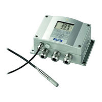
Vaisala HUMICAP HMT330 SERIES User Manual (161 pages)
Humidity and Temperature
Brand:
Vaisala
| Category:
Transmitter
| Size: 2.39 MB
Table of Contents
Table of Contents
3
Chapter 1 General Information
11
About this Manual
11
Contents of this Manual
11
General Safety Considerations
12
Feedback
12
Product Related Safety Precautions
13
ESD Protection
13
Recycling
14
Trademarks
14
License Agreement
14
Warranty
15
Chapter 2 Product Overview
17
Introduction to HMT330
17
Table 1 Quantities Measured by HMT330
17
Basic Features and Options
18
Table 2 Optional Quantities Measured by HMT330
18
Figure 1 Transmitter Body
19
Figure 2 Inside of Open Transmitter
20
Figure 3 Probe Options
21
Probe Options
21
Warmed Probe HMT337
22
Chapter 3 Installation
23
Mounting the Housing
23
Standard Mounting Without Mounting Plate
23
Figure 4 Standard Mounting
23
Wall Mounting with Wall Mounting Kit
24
Figure 5 Mounting with Wall Mounting Kit
24
Figure 6 Dimensions of Plastic Mounting Plate
24
Mounting with DIN Rail Installation Kit
25
Figure 7 Mounting with DIN Rail Installation Kit
25
Pole Installation with Installation Kit for Pole or Pipeline
26
Figure 8 Vertical Pole
26
Figure 9 Horizontal Pole
26
Figure 10 Mounting with Metal Wall Mounting Plate
27
Figure 11 Dimensions of Metal Mounting Plate (MM)
27
Mounting Rain Shield with Installation Kit
28
Figure 12 Mounting Rain Shield with Installation Kit
28
Panel Mounting Frame
29
Figure 13 Panel Mounting with Frame
29
Figure 14 Panel Mounting Dimensions
29
Wiring
30
Cable Bushings
30
Figure 15 Cable Bushings
30
Grounding the Cables
31
Figure 16 Grounding the Screen of Electrical Cable
31
Grounding the Transmitter Housing
32
Signal and Power Supply Wiring
33
Figure 17 Screw Terminal Block on Motherboard
33
Connections to 24 VAC Power Supply
34
Figure 18 Connections to 24 VAC Power Supply
35
Probe Mounting
36
Figure 19 Measurement Error at 100 %RH
36
Figure 20 Horizontal Mounting of Sensor Head
37
General Instructions for Probes with Cable
37
Figure 21 Vertical Mounting of Sensor Head
38
HMT333 for Ducts and Tight Spaces
39
HMT334 for High Pressure and Vacuum Applications
39
Figure 22 HMT344 Probe
40
Figure 23 Tightening the Nut
40
Figure 24 Cleaning of Tightening Cone
41
HMT335 for High Temperatures
42
HMT337 for High Humidity Applications
42
Temperature Probe (Optional)
42
Figure 25 HMT338 Probe
43
HMT338 for Pressurized Pipelines
43
Table 3 HMT338 Probe Dimensions
43
Figure 26 Sealing of Fitting Body into Process
44
Figure 27 Tightening the Clasp Nut
44
Tightening the Clasp Nut
44
Optional Modules
46
Power Supply Module
46
Installation
47
Warnings
48
Figure 29 Galvanic Output Isolation Module
50
Figure 30 Third Analog Output
50
Galvanic Isolation for Output
50
Third Analog Output
50
Installation and Wiring
51
Installation and Wiring
52
Relays
52
Selecting the Activation State of the Relay
52
Figure 31 Relay Module
53
Figure 32 RS-485 Module
54
Installation and Wiring
54
RS-422/485 Interface
54
Table 4 Connecting the Twisted Pair Wires to the Screw Terminals
54
Figure 33 4-Wire RS-485 Bus
55
Table 5 4-Wire (Switch 3: On)
55
Table 6 2-Wire (Switch 3: Off)
56
8-Pin Connector
57
Figure 34 Wiring of Optional 8-Pin Connector
57
Table 7 Wiring of 8-Pin Connector
57
Chapter 4 Operation
59
Getting Started
59
Display/Keypad (Optional)
59
Basic Display
59
Graphic History
60
Figure 35 Basic Display
60
Figure 36 Graphical Display
60
Menus and Navigation
61
Table 8 Periods for Trend and Max/Min Calculations
61
Table 9 Graph Information Messages in Cursor Mode
61
Figure 37 Main Menus
62
Language Setting
62
Display Backlight Setting
63
Display Contrast Setting
63
Rounding Setting
63
Keypad Lock (Key Guard)
64
Menu PIN Lock
64
Factory Settings
65
MI70 Link Program for Data Handling
65
Serial Line Communication
65
Figure 38 Service Port Connector and User Port Terminal on Mother
66
User Port Connection
66
Board
66
Figure 39 Connection Example between PC Serial Port and User Port
66
Table 10 Default Serial Communication Settings for the User Port
66
Service Port Connection
67
Table 11 Fixed Communication Settings for Service Port
67
Figure 40 Starting Hyper Terminal Connection
68
Terminal Program Settings
68
Figure 41 Connecting to Hyper Terminal
69
Figure 42 Hyper Terminal Serial Port Settings
69
List of Serial Commands
70
Getting Measurement Message from Serial Line
72
Outputting Reading Once
72
Send
72
Stopping Continuous Outputting
72
Send D
73
Formatting Serial Line Message
74
FTIME and FDATE
74
TIME and DATE
74
Fst
75
General Settings
76
Changing Quantities and Units
76
Using Display/Keypad
76
Form
77
Table 12 FORM Command Modifiers
77
Using Serial Line
77
Unit
78
Pressure Compensation Setting
79
Table 13 Multiplication Factors
80
User Port Serial Settings
80
Using Serial Line
81
Smode
82
Table 14 Selection of Output Modes
82
Echo
83
Table 15 Filtering Levels
83
Figure 43 Device Information on Display
84
Filt
84
Help
85
Errs
86
Resetting Transmitter by Using Serial Line
87
Data Recording
89
View Recorded Data
90
Play
91
Deleting the Recorded Files
92
Figure 44 Current/Voltage Switches of Output Modules
93
Analog Output Settings
93
Analog Output Quantities
95
Analog Output Tests
97
Analog Output Fault Indication Setting
98
Figure 45 Measurement-Based Relay Output Modes
99
Operation of Relays
99
Hysteresis
100
Figure 46 FAULT/ONLINE STATUS Relay Output Modes
101
Figure 47 Relay Indicators on Display
102
Enabling/Disabling Relays
102
Rsel
103
Testing Operation of Relays
105
Operation of RS-485 Module
106
Echo
107
Intv
108
Send
109
Figure 48 Decrease of Sensor Gain
110
Sensor Functions
110
Automatic Chemical Purge (Interval Purge)
111
Figure 49 Purge Buttons on Motherboard
112
Figure 50 Chemical Purge Settings
112
Starting and Configuring Chemical Purge
112
Figure 51 Performing Chemical Purge
113
Using Serial Line
113
Sensor Heating
115
Chapter 5 Maintenance
117
Figure 52 Changing the Sensor
118
Error States
119
Figure 53 Error Indicator and Error Message
119
Table 16 Error Messages
120
Chapter 6 Calibration and Adjustment
121
Figure 54 Adjustment and Purge Buttons
122
Figure 55 Adjustment Menu
122
Table 17 Indicator Led Functions
122
Relative Humidity Adjustment
123
Figure 56 Selecting Point 1 Reference Type
124
Using Display/Keypad
124
Using Serial Line
125
Relative Humidity Adjustment after Sensor Change
126
Temperature Adjustment
127
Analog Output Adjustment
129
Feeding Adjustment Information
130
Chapter 7 Technical Data .................................................................................... 129
131
Specifications
131
Figure 57 Accuracy over Temperature Range
132
Temperature (+ Operating Pressure Ranges)
132
Table 18 Calculated Variables (Typical Ranges)
133
Accuracy of Mixing Ratio G/Kg (Ambient Pressure
134
Dewpoint Temperature (HMT337 Warmed Probe Option)
135
Figure 58 Accuracy in Dewpoint Measurement
135
Inputs and Outputs
136
Table 19 Transmitter Weights (in Kg/Lb)
137
Relay Module
138
Figure 59 Transmitter Body Dimensions
141
Figure 60 HMT331 Probe Dimensions
142
Figure 61 HMT333 Probe Dimensions
142
Figure 62 HMT334 Probe Dimensions
143
Figure 63 HMT335 Probe Dimensions
143
Figure 64 HMT337 Probe Dimensions
144
Figure 65 HMT338 Probe Dimensions
144
Figure 66 Optional Temperature Probe Dimensions
144
Technical Support
145
Vaisala Service Centers
146
Appendix A Probe Installation Kits and Installation Examples
147
Duct Installation Kits (for HMT333/337/335)
147
Figure 67 Duct Mounting Installation Kit
147
Duct Installation Kit for Temperature Probe (for HMT337)146
148
Figure 68 Duct Mounting Installation Kit for T-Probe
148
Pressure Tight Swagelok Installation Kits (for HMT337)
149
Temperature Probe Installation
149
Figure 69 Swagelok Installation Kit for RH-Probe
149
Figure 70 Swagelok Installation Kit for T-Probe
149
Examples of Vapor Tight Installations with Cable Gland
150
RH-Probe Installations (for HMT333/337)
150
Figure 71 Cable Installation with Cable Gland
150
Figure 72 Probe Head Installation with Cable Gland
150
T- Probe Installations (HMT337)
151
Figure 73 Vapor Tight Installation
151
Figure 74 Wall Mounting Installation
151
Example of Climate Chamber Installation
152
Figure 75 Climate Chamber Installation (Not Available from Vaisala)
152
Example of Installation through Roof
153
Figure 76 Example of Installation through Roof
153
Ball Valve Installation Kit for HMT338
154
Figure 77 Installing Sensor Head through Ball Valve Assembly
154
Figure 78 Meteorological Installation Kit for Outdoor Installation
156
Meteorological Installation Kit (for HMT337)
156
Appendix Bcalculation Formulas
157
Vaisala HUMICAP HMT330 SERIES Quick Reference Manual (40 pages)
Brand:
Vaisala
| Category:
Transmitter
| Size: 0.84 MB
Table of Contents
Things to Consider
3
Operation
4
Starting Operation
6
Maintenance
6
Betrieb
8
Wartung
10
Puesta en Servicio
14
Mantenimiento
14
Huomioon Otettavaa
15
Käytön Aloittaminen
18
À Propos de Ce Guide de Démarrage Rapide
19
Over Deze Beknopte Handleiding
23
Advertisement
Vaisala HUMICAP HMT330 SERIES Manual (3 pages)
Industrial Transmitters
Brand:
Vaisala
| Category:
Transmitter
| Size: 2.07 MB
Advertisement
Related Products
Vaisala HUMICAP HMT333
Vaisala HUMICAP HMT334
Vaisala HUMICAP HMT335
Vaisala HUMICAP HMT337
Vaisala HUMICAP HMT338
Vaisala HMT360Series
Vaisala HUMICAP HMT365
Vaisala HUMICAP HMT362
Vaisala HMT370EX
Vaisala HUMICAP HMT360 SERIES
Vaisala Categories
Transmitter
Measuring Instruments
Accessories
Test Equipment
Weather Station
More Vaisala Manuals
Login
Sign In
OR
Sign in with Facebook
Sign in with Google
Upload manual
Upload from disk
Upload from URL