Sign In
Upload
Manuals
Brands
Vaisala Manuals
Transmitter
HUMICAP HMT310
Vaisala HUMICAP HMT310 Manuals
Manuals and User Guides for Vaisala HUMICAP HMT310. We have
2
Vaisala HUMICAP HMT310 manuals available for free PDF download: User Manual
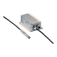
Vaisala HUMICAP HMT310 User Manual (88 pages)
Humidity and Temperature Transmitter
Brand:
Vaisala
| Category:
Transmitter
| Size: 0.86 MB
Table of Contents
Table of Contents
3
Vaisala
3
Chapter 1 General Information
9
About this Manual
9
Contents of this Manual
9
Version Information
10
General Safety Considerations
10
Feedback
10
Table 1 Manual Revisions
10
Product Related Safety Precautions
11
ESD Protection
11
Recycling
12
Regulatory Compliances
12
Emissions
13
Immunity
13
Trademarks
13
Warranty
13
Chapter 2 Product Overview
17
Introduction to HMT310
17
Components
18
Figure 1 HMT310 Components
18
Probe Options
19
Figure 2 HMT310 Probes
19
Output Quantities
20
Table 2 HMT310 Output Quantities
20
Chapter 3 Installation
21
Selecting Location
21
Mounting
21
Mounting the Transmitter/Removing the Transmitter Unit
21
Figure 3 Mounting with Mounting Plates
22
Mounting the Probes
23
Beware of Temperature Differences
23
Figure 4 Mounting Plate Dimensions
23
General Instructions for Probes with Cable
24
Figure 5 Measurement Error at 100 %RH When Difference between Ambient and Sensor Temperature Is 1 °C
24
Figure 6 Horizontal Mounting of Probe
24
HMT313 for General Use
25
Figure 7 Vertical Mounting of Probe
25
HMT314 for Pressurized Spaces
26
Figure 8 HMT314 Installation
26
Figure 9 Marking the Nut
27
HMT315 for High Temperatures
28
HMT317 for Demanding Processes
28
HMT318 for Pressurized Pipelines
29
Figure 10 HMT318 Probe Dimensions (in MM)
29
Table 3 HMT318 Probe Dimensions
29
Tightening the Clasp Nut
30
Figure 11 Sealing of Fitting Body into Process
30
Figure 12 Tightening the Clasp Nut
30
Connections
32
Cable Wiring
32
Figure 13 8-Pole Connector
32
Screw Terminal Connector
33
Figure 14 Screw Terminal Connector
33
Entering Serial Communication Parameters
35
Table 4 Entering Serial Parameters in Windows 2000 and Windows NT
36
Chapter 4 Operation
35
Power ON/OFF
35
List of Commands
37
Figure 15 Hyperterminal Settings in Windows
37
Measurement Output
39
R Start Continuous Outputting
39
S Stop Continuous Outputting
39
INTV Set Continuous Output Interval for RUN-Mode
40
SEND Output Reading Once
40
SMODE Set Serial Interface Mode
40
SERI Serial Line Settings
41
ADDR Set Transmitter Address for Use in POLL-Mode
41
OPEN Temporarily Open Transmitter from POLL-Mode to Receive Serial Commands
42
CLOSE Set Transmitter in POLL-Mode
42
Output Formatting
43
FORM Serial Output Format
43
TIME, DATE Setting Time and Date
44
Table 5 Quantity Abbreviations for FORM Command
44
Table 6 Modifiers
44
FTIME, FDATE Add Time and Date to SEND and R Outputs
45
UNIT Select Metric or Nonmetric Output Units
45
FST Output State of Chemical Purge or Sensor Heating (with SEND and R Commands)
46
Table 7 Output Quantities and Their Metric and Nonmetric Units
46
Other Commands
47
Check Transmitter Settings
47
ECHO Serial Bus Echo
48
FIND All Devices in POLL-Mode Send Their Addresses
48
HELP List Commands
48
PRES Set Ambient Pressure for Calculations
48
Table 8 Pressure Conversion Chart
49
FILT Set Result Filtering
50
RESET Reset Transmitter
50
ERRS Display Error Messages
50
Setting, Scaling and Testing Analog Outputs
51
AMODE Set Analog Outputs (0/4
51
ASEL Select Parameter for Analog Outputs
51
ASCL Scale Analog Outputs
52
Table 9 Output Quantities and Their Metric and Nonmetric Units
52
ITEST Test Analog Outputs
53
AQTEST Test Analog Outputs for Desired Readings
53
AERR Set Error Outputs
54
Chemical Purge (Optional)
54
General
54
Automatic/Manual Chemical Purge
55
Automatic Chemical Purge Settings
55
PUR Turn ON/OFF Automatic Chemical Purge
55
Figure 16 Decrease of Sensor Gain Due to Interfering Chemical and Effect of Chemical Purge Process
55
PUR Set Chemical Purge Interval
56
PURR Chemical Purge in Powerup
56
Chemical Purge Activated Manually
57
Starting Manual Chemical Purge
57
Sensor Heating
57
General
57
Setting Humidity Sensor Heating
58
Sensor Heating ON/OFF
58
Setting Heating Parameters
59
Chapter 5
61
Pressure Regulator Recommended
61
Measuring at Overpressure
61
Chapter 6 Maintenance
63
Periodic Maintenance
63
Calibration Interval
63
Replacing Consumables
63
Filter Change
63
Sensor Change
63
Parts List for Consumables
64
Technical Support
64
Table 10 Available Spare Parts
64
Return Instructions
65
Vaisala Service Centers
66
Chapter 7 Calibration and Adjustment
67
Calibration and Adjustment Commands
67
LI Revert Factory Calibration
67
FCRH Relative Humidity Calibration after Sensor Change
68
CTEXT Set Calibration Information Text
68
CDATE Set Calibration Date
68
ACAL Analog Output Calibration
69
Relative Humidity Calibration and Adjustment (in Two Points)
69
Low End Adjustment
70
Figure 17 Location of Adjustment Button
70
High End Adjustment
71
Temperature Calibration and Adjustment (in One Point)
72
Chapter 8 Technical Data
73
Specifications
73
Table 11 Relative Humidity Specifications
73
Figure 18 Accuracy over Temperature Range
74
Table 12 Temperature Specifications
74
Table 13 Electronics Specifications
75
Table 14 Mechanics Specifications
75
Options and Accessories
76
Table 15 Options and Accessories
76
Dimensions in MM (Inches)
77
Transmitter Enclosure and Mounting Plates
77
Figure 19 Transmitter Enclosure and Mounting Plate Dimensions
77
Probes
78
Hmt311
78
Hmt313
78
Figure 20 Probe Dimensions
78
Figure 21 HMT313 Dimensions
78
Hmt314
79
Hmt315
79
Figure 22 HMT314 Dimensions
79
Figure 23 HMT315 Dimensions
79
Hmt317
80
Hmt318
80
Figure 24 HMT317 Dimensions
80
Figure 25 HMT318 Dimensions
80
Appendix A Probe Installation Kits and Installation Examples
81
Duct Installation Kits (for HMT313/317/315)
81
Figure 26 Duct Installation Kit
81
Pressure-Tight Swagelok Installation Kits (for HMT317)
82
RH Probe Installation
82
Figure 27 Swagelok Installation Kit for RH Probe
82
Examples of Vapor-Tight Installations with Cable Gland
83
RH Probe Installations (for HMT313/317)
83
Figure 28 Cable Installation with Cable Gland AGRO
83
Ball Valve Installation Kit for HMT318
84
Figure 29 Probe Installation with Cable Gland (Not Available from Vaisala)
84
Figure 30 Installing the HMT318 Probe through a Ball Valve Assembly
85
Advertisement
Vaisala HUMICAP HMT310 User Manual (89 pages)
Humidity and Temperature Transmitter
Brand:
Vaisala
| Category:
Transmitter
| Size: 1.1 MB
Table of Contents
Table of Contents
3
Chapter 1 General Information
9
About this Manual
9
Contents of this Manual
9
Version Information
10
General Safety Considerations
10
Table 1 Manual Revisions
10
Feedback
11
Product Related Safety Precautions
11
ESD Protection
11
Recycling
12
Regulatory Compliances
12
Electromagnetic Compatibility
12
Emissions
13
Immunity
13
Trademarks
13
Warranty
14
Chapter 2 Product Overview
15
Introduction to HMT310
15
Components
16
Figure 1 HMT310 Components
16
Probe Options
17
Figure 2 HMT310 Probes
17
Output Quantities
18
Table 2 HMT310 Output Quantities
18
Chapter 3 Installation
19
Selecting Location
19
Mounting
19
Mounting the Transmitter/Removing the Transmitter Unit
19
Figure 3 Mounting with Mounting Plates
20
Mounting the Probes
21
Beware of Temperature Differences
21
Figure 4 Mounting Plate Dimensions
21
General Instructions for Probes with Cable
22
Figure 5 Measurement Error at 100 %RH When Difference between Ambient and Sensor Temperature Is 1 °C
22
Figure 6 Horizontal Mounting of Probe
22
Figure 7 Vertical Mounting of Probe
23
HMT313 for General Use
24
HMT314 for Pressurized Spaces
24
Figure 8 HMT314 Installation
25
Figure 9 Marking the Nut
25
HMT315 for High Temperatures
26
HMT317 for Demanding Processes
26
HMT318 for Pressurized Pipelines/Oils
27
Figure 10 HMT318 Probe Dimensions (in MM)
27
Figure 11 Sealing of Fitting Body into Process
28
Table 3 HMT318 Probe Dimensions
28
Tightening the Clasp Nut
29
Figure 12 Tightening the Clasp Nut
29
Connections
30
Cable Wiring
30
Figure 13 8-Pole Connector
30
Screw Terminal Connector
31
Figure 14 Screw Terminal Connector
31
Chapter 4 Operation
33
Power ON/OFF
33
Entering Serial Communication Parameters
33
Table 4 Entering Serial Parameters in Windows® 2000 and Windows NT
34
List of Commands
35
Figure 15 Hyperterminal Settings in Windows ® 2000 Environment
35
Measurement Output
37
R Start Continuous Outputting
37
S Stop Continuous Outputting
38
INTV Set Continuous Output Interval for RUN-Mode
38
SEND Output Reading Once
38
SMODE Set Serial Interface Mode
39
SERI Serial Line Settings
39
ADDR Set Transmitter Address for Use in POLL-Mode
40
OPEN Temporarily Open Transmitter from POLL-Mode to Receive Serial Commands
40
CLOSE Set Transmitter in POLL-Mode
41
Output Formatting
41
FORM Serial Output Format
41
Table 5 Quantity Abbreviations for FORM Command
42
Table 6 Modifiers
42
TIME, DATE Setting Time and Date
43
FTIME, FDATE Add Time and Date to SEND and R Outputs41
43
UNIT Select Metric or Nonmetric Output Units
44
Table 7 Output Quantities and Their Metric and Nonmetric Units
44
FST Output State of Chemical Purge or Sensor Heating (with SEND and R Commands)
45
Other Commands
46
Check Transmitter Settings
46
ECHO Serial Bus Echo
46
FIND All Devices in POLL-Mode Send Their Addresses
47
HELP List Commands
47
PRES Set Ambient Pressure for Calculations
47
Table 8 Pressure Conversion Chart
48
FILT Set Result Filtering
49
RESET Reset Transmitter
49
ERRS Display Error Messages
49
Setting, Scaling and Testing Analog Outputs
50
AMODE Set Analog Outputs (0/4
50
ASEL Select Parameter for Analog Outputs
50
Table 9 Output Quantities and Their Metric and Nonmetric Units
51
ASCL Scale Analog Outputs
52
ITEST Test Analog Outputs
52
AQTEST Test Analog Outputs for Desired Readings
53
AERR Set Error Outputs
53
Chemical Purge (Optional)
54
General
54
Automatic/Manual Chemical Purge
55
Automatic Chemical Purge Settings
55
PUR Turn ON/OFF Automatic Chemical Purge
55
Figure 16 Decrease of Sensor Gain Due to Interfering Chemical and Effect of Chemical Purge Process
55
PUR Set Chemical Purge Interval
56
PURR Chemical Purge in Powerup
56
Chemical Purge Activated Manually
57
Starting Manual Chemical Purge
57
Sensor Heating
58
General
58
Setting Humidity Sensor Heating
58
Sensor Heating ON/OFF
58
Setting Heating Parameters
59
Measuring at Overpressure
60
Chapter 5 Measuring at Overpressure
60
Pressure Regulator Recommended
60
Chapter 6 Maintenance
62
Periodic Maintenance
62
Calibration Interval
62
Replacing Consumables
62
Filter Change
62
Sensor Change
63
Parts List for Consumables
63
Table 10 Available Spare Parts
63
Technical Support
64
Return Instructions
64
Vaisala Service Centers
65
Chapter 7 Calibration and Adjustment
66
Calibration and Adjustment Commands
66
LI Revert Factory Calibration
66
FCRH Relative Humidity Calibration after Sensor Change
67
CTEXT Set Calibration Information Text
67
CDATE Set Calibration Date
68
ACAL Analog Output Calibration
68
Relative Humidity Calibration and Adjustment (in Two Points)
69
Figure 17 Location of Adjustment Button
69
Low End Adjustment
70
High End Adjustment
70
Temperature Calibration and Adjustment (in One Point)
71
Chapter 8 Technical Data
74
Specifications
74
Table 11 Relative Humidity Specifications
74
Figure 18 Accuracy over Temperature Range
75
Table 12 Temperature Specifications (+ Operating Pressure Ranges)
75
Table 13 Electronics Specifications
76
Table 14 Mechanics Specifications
76
Options and Accessories
77
Table 15 Options and Accessories
77
Dimensions in MM (Inches)
78
Transmitter Enclosure and Mounting Plates
78
Probes
79
Hmt311
79
Hmt313
79
Hmt314
80
Hmt315
80
Hmt317
81
Hmt318
81
Appendix A
82
Duct Installation Kits (for HMT313/317/315)
82
Figure 19 Duct Installation Kit
82
Probe Installation Kits and Installation Examples
82
Pressure-Tight Swagelok Installation Kits (for HMT317)
83
RH Probe Installation
83
Figure 20 Swagelok Installation Kit for RH Probe
83
Examples of Vapor-Tight Installations with Cable Gland
84
RH Probe Installations (for HMT313/317)
84
Figure 21 Cable Installation with Cable Gland AGRO
84
Ball Valve Installation Kit for HMP318
85
Figure 23 Installing the HMP318 Probe through a Ball Valve Assembly
86
Advertisement
Related Products
Vaisala HUMICAP HMT360 SERIES
Vaisala HUMICAP HMT330 SERIES
Vaisala HMT360Series
Vaisala HUMICAP HMT361
Vaisala HUMICAP HMT363
Vaisala HUMICAP HMT364
Vaisala HUMICAP HMT365
Vaisala HUMICAP HMT367
Vaisala HUMICAP HMT368
Vaisala HUMICAP HMT333
Vaisala Categories
Transmitter
Measuring Instruments
Accessories
Test Equipment
Weather Station
More Vaisala Manuals
Login
Sign In
OR
Sign in with Facebook
Sign in with Google
Upload manual
Upload from disk
Upload from URL