Sign In
Upload
Manuals
Brands
Vaisala Manuals
Transmitter
hmdw110 series
Vaisala hmdw110 series Manuals
Manuals and User Guides for Vaisala hmdw110 series. We have
3
Vaisala hmdw110 series manuals available for free PDF download: Quick Manual, User Manual
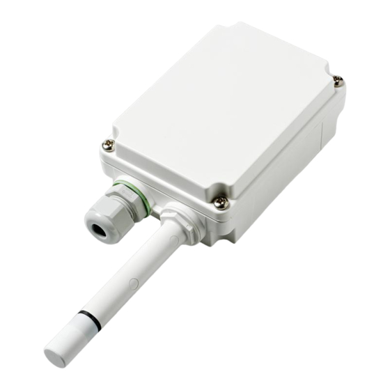
Vaisala hmdw110 series User Manual (92 pages)
Humidity and Temperature Transmitter Series
Brand:
Vaisala
| Category:
Transmitter
| Size: 4.45 MB
Table of Contents
Table of Contents
3
1 About this Document
9
Version Information
9
Related Manuals
9
Documentation Conventions
9
Table Document Versions (English)
9
Table 2 Related Manuals
9
Trademarks
10
2 Product Overview
11
Introduction to HMDW110 Series
11
Output Parameters Explained
11
Table 3 HMDW110 Series Output Parameters
11
HMD110/112 Parts
12
Figure 1 HMD110/112 Parts
12
HMW110/112 Parts
13
Figure 2 HMW110/112 Parts
13
HMS110/112 Parts
14
Figure 3 HMS110/112 Parts
14
Component Board
15
Figure 4 HMDW110 Series Component Board
15
Analog Output Overrange Behavior
16
Safety
16
ESD Protection
16
Regulatory Compliances
17
3 Installation
18
Selecting Location
18
HMD110/112 Installation
18
Figure 5 HMD110/112 Installation
19
Figure 6 HMD110/112 Centering Inside Duct
19
HMW110/112 Installation
20
Figure 7 HMW110/112 Installation
21
HMS110/112 Installation
22
Wiring Devices with Analog Output
26
Figure 8 HMDW110 Wiring, Analog Output
26
Figure 10 HMDW110 Supply Voltage Operating Region
27
Figure 9 HMDW110 Wiring with Single Power Supply
27
HMDW110 Power Supply Requirements
27
Wiring both Current Loops with a Single Power Supply
27
Figure 11 HMDW110 Wiring with RDP100 Remote Display Panel
28
Wiring HMDW110 with RDP100 Remote Display Panel
28
Wiring Devices with Modbus Output
29
Figure 12 HMDW110 Wiring, Modbus Output
29
4 Modbus Communication
30
Table 4 Default Modbus Serial Communication Settings
30
5 Vaisala Insight Software
31
Connecting to Insight Software
32
6 Using Service Port with Terminal Application
33
Connecting to Service Port
33
Terminal Application Settings
33
Figure 13 Putty Terminal Application
34
Accessing Service Port Command Interface in Devices with Modbus Output
35
Serial Commands
35
Table 5 HMDW110 Serial Commands
36
Device Information and Status
37
Table 6 ? Command
37
Table 7 Errs Command
38
Table 8 Error Messages on ERRS Command
38
Table 9 Help Command
39
Table 10 System Command
40
Serial Line Output and Communication
41
Measurement Output
41
Table 11 Time Command
41
Table 12 Send Command
41
Table 13 R Command
42
Table 14 S Command
42
Table 15 Intv Command
42
Measurement Output Format
43
Table 16 Unit Command
43
Table 17 Form Command
43
Table 18 Output Parameters for Form Command
44
Table 19 Modifiers for Form Command
44
Serial Line Communication
45
Table 20 Open Command
45
Table 21 Close Command
45
Table 22 Addr Command
45
Table 23 Seri Command
46
Table 24 Sdelay Command
46
Table 25 Smode Command
47
Analog Output
48
Table 26 Aerr Command
48
Table 27 Amode Command
48
Table 28 Aover Command
48
Table 29 Asel Command
49
Calibration and Adjustment Commands
50
Table 30 Cdate Command
50
Table 31 Crh Command
50
Table 32 Crhclr Command
51
Table 33 Ct Command
51
Table 34 Ctclr Command
51
Table 35 Ctext Command
52
Table 36 Fcrh Command
52
Table 37 L Command
52
Table 38 Li Command
53
Other Commands
54
Table 39 Filt Command
54
Table 40 Frestore Command
54
Table 41 Reset Command
55
7 Maintenance
56
Cleaning
56
Calibration and Adjustment
56
Adjustment Types
57
Adjustment Points
57
Calibration and Adjustment Using Handheld Meter and Reference Probe
58
One-Point Humidity Calibration and Adjustment Using Handheld Meter and HMK15 Humidity Calibrator
60
Two-Point Humidity Calibration and Adjustment Using Computer and HMK15 Humidity Calibrator
61
Two-Point Temperature Calibration and Adjustment Using Computer
64
Replacing HUMICAP Sensor on HMD110/112 and HMW110/112
67
Replacing HUMICAP Sensor on HMS110/112
69
Filter Selection
70
8 Troubleshooting
71
Problem Situations
71
Error Messages in Insight Software
72
Table 42 Error Messages in Insight Software
72
Error Codes in MI70 Handheld Meter
73
Table 43 Error Codes in MI70
73
Unknown Serial Settings
74
9 Technical Data
75
Table 44 Measurement Performance
75
Table 45 Operating Environment (All Models)
76
Table 46 Mechanical Specifications
76
Table 47 Inputs and Outputs
76
Dimensions
77
Figure 14 HMS110/112 Dimensions
77
Figure 15 HMD110/112 Dimensions
77
Spare Parts and Accessories
78
Figure 16 HMW110/112 Dimensions
78
Table 48 Spare Parts and Accessories
78
Appendix A: Modbus Reference
80
Default Communication Settings
80
Function Codes
80
Data Encoding
80
Table 49 Default Modbus Serial Communication Settings
80
Table 50 Modbus Function Codes
80
Modbus Registers
81
Measurement Data Registers
81
Table 51 Modbus Measurement Data Registers (Read-Only)
81
A.4 Modbus Registers
81
Status Registers
82
Table 52 Modbus Status Registers (Read-Only)
82
Table 53 Error Codes on Modbus Interface
82
A.4.2 Status Registers
82
Configuration Registers
83
Table 54 Modbus Configuration Data Registers (Writable)
83
A.4.3 Configuration Registers
83
Test Value Registers
84
Device Identification Objects
84
Table 55 Modbus Test Registers (Read-Only)
84
Table 56 Device Identification Objects
84
Modbus Communication Examples
85
Warranty
89
Technical Support
89
Advertisement
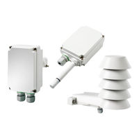
Vaisala hmdw110 series Quick Manual (108 pages)
Humidity and Temperature Transmitter
Brand:
Vaisala
| Category:
Transmitter
| Size: 3.24 MB
Table of Contents
Table of Contents
80
2 服务端口接头(4 针 M8)
86
1 4
86
3 输出的接线端子排。用于 Modbus 或 RDP100 远程显示面板连接
86
将变送器连接到 Pc 之前
87
如果端子 5
87
如果其他接线端子排已接线(端子 1
87
压的连接,防止接地回路可能导致的设备损坏。接线端子排和服务端口的位 置显示在电路板
87
RDP100 远程显示面板或 Modbus (RS-485) 主机之间的通信干扰您的连接
87
3 Pwr-
97
4 Pwr
97
Rs485- 1 Rs485
97
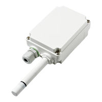
Vaisala hmdw110 series User Manual (62 pages)
humidity and temperature transmitters
Brand:
Vaisala
| Category:
Transmitter
| Size: 3 MB
Table of Contents
Table of Contents
3
1 General Information
5
About this Document
5
Documentation Conventions
5
Safety
6
ESD Protection
6
Recycling
6
Trademarks
6
Software License
7
Warranty
7
2 Product Overview
8
HMDW110 Series Overview
8
Output Parameters Explained
9
HMD110/112 Parts
10
HMW110/112 Parts
11
HMS110/112 Parts
12
Component Board
13
Analog Output Overrange Behavior
14
3 Installation
15
Selecting Location
15
HMD110/112 Installation
16
HMW110/112 Installation
18
HMS110/112 Installation
19
Wiring HMDW110
21
Wiring both Current Loops with a Single Power Supply
22
HMDW110 Power Supply Requirements
22
Wiring HMDW110 with RDP100
23
4 Service Port
24
Connecting to the Service Port
24
Terminal Application Settings
25
Serial Commands
26
Device Information and Status
27
Serial Line Output and Communication
30
Measurement Output
30
Measurement Output Format
31
Serial Line Communication
33
Analog Output
35
Calibration and Adjustment Commands
38
Other Commands
41
5 Maintenance
43
Cleaning
43
Calibration and Adjustment
43
Adjustment Types
44
Adjustment Points
44
Calibration and Adjustment Using a Hand-Held Meter and a Reference Probe
45
One-Point Humidity Calibration and Adjustment Using a Hand-Held Meter and HMK15 Humidity Calibrator
47
Two-Point Humidity Calibration and Adjustment Using a Computer and a HMK15 Humidity Calibrator
48
Two-Point Temperature Calibration and Adjustment Using a Computer
51
Replacing the HUMICAP® Sensor on HMD110/112 and HMW110/112
53
Replacing the HUMICAP® Sensor on HMS110/112
54
Troubleshooting
56
Error Messages
56
Technical Support
57
Product Returns
57
6 Technical Data
58
Specifications
58
Dimensions
60
Spare Parts and Accessories
61
Advertisement
Advertisement
Related Products
Vaisala INTERCAP HMDW80 SERIES
Vaisala HMDW20
Vaisala HMDW30
Vaisala HMDW60
Vaisala INTERCAP HMDW82
Vaisala INTERCAP HMDW82D
Vaisala INTERCAP HMDW83
Vaisala INTERCAP HMDW83D
Vaisala HMD60 Series
Vaisala INTERCAP HMD82
Vaisala Categories
Transmitter
Measuring Instruments
Accessories
Weather Station
Test Equipment
More Vaisala Manuals
Login
Sign In
OR
Sign in with Facebook
Sign in with Google
Upload manual
Upload from disk
Upload from URL