Sign In
Upload
Manuals
Brands
Vaisala Manuals
Transmitter
Drycap DMT152
Vaisala Drycap DMT152 Manuals
Manuals and User Guides for Vaisala Drycap DMT152. We have
3
Vaisala Drycap DMT152 manuals available for free PDF download: User Manual
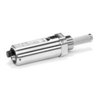
Vaisala Drycap DMT152 User Manual (72 pages)
Dew Point Transmitter
Brand:
Vaisala
| Category:
Transmitter
| Size: 1.73 MB
Table of Contents
Table of Contents
3
1 About this Document
9
Version Information
9
Related Manuals
9
Documentation Conventions
9
Table Document Versions (English)
9
Table 2 Related Manuals
9
Trademarks
10
2 Product Overview
11
Introduction to DMT152
11
Basic Features and Options
11
Table 3 DMT152 Measurement Parameters
11
Transmitter Structure
12
Figure 1 DMT152 Probe Parts
12
Safety
13
ESD Protection
13
Regulatory Compliances
13
3 Functional Description
14
Advanced DRYCAP Technology
14
Auto-Calibration
14
Sensor Purge
14
4 Installation
15
Selecting the Location
15
Installing the Transmitter
15
Figure 2 DMT152 Installed Directly to Pipeline (Max. 50 Bar)
15
Wiring
17
Table 4 Standard Wiring Pinouts and Wire Colors
17
Figure 3 Connectors I and II
18
Figure 4 Connector Pinout
18
Figure 5 Output Noise Minimization Wiring Option
19
Output Noise Minimization Option
19
Table 5 Output Noise Minimization Wiring Option Pinouts and
19
Connection Cables
20
Table 6 Connection Cable Options
20
Power Supply Requirements
21
Loop-Powered Display
21
Sampling from Process
22
Figure 6 Nokeval 301 Loop-Powered Display
22
Figure 7 DMT152 Nokeval 301/302 Wiring Diagram
22
Sampling Accessories
23
DMT242SC Sampling Cell
23
DMT242SC2 Sampling Cell with Swagelok Connectors
23
DSC74 Sampling Cell with Quick Connector and Leak Screw
24
Figure 8 Sampling Cells DMT242SC2 (Left) and DMT242SC (Right)
24
DSC74B Two-Pressure Sampling Cell
25
Figure 9 DSC74 Sampling Cell with Accessories
25
Figure 10 DSC74B
26
DSC74C Two-Pressure Sampling Cell with Coil
27
Figure 11 Removing the Leak Screw
27
Figure 12 Default Assembly of DSC74C
28
Figure 13 Alternative Assembly of DSC74C (for Tight Spaces)
29
NW40 Mounting Flange
30
Figure 14 NW40 Mounting Flange
30
Figure 15 NW40 Mounting Flange Dimensions
30
5 Serial Line Operation
31
Connecting to Serial Interface
31
Installing Driver for USB Service Cable
31
Terminal Application Settings
31
Table 7 Default Serial Interface Settings
31
List of Serial Commands
33
Table 8 List of Serial Commands
33
Device Information
35
Show Device Information
35
Show Transmitter Status
35
Table 9 ? Command
35
Show Firmware Version
36
Table 10 STAT Command
36
Table 11 VERS Command
36
Configuring Analog Outputs
37
Table 12 AMODE Command
37
Limit Alarm
38
Table 13 ALARM Command
38
Purge Status Alarm
39
Malfunction Alarm
40
Table 14 STATUS Command
40
Table 15 AERR Command
40
Select Analog Output Parameter and Scaling
41
Configuring Serial Line Operation
41
Set Serial Line Settings
41
Table 16 ASEL Command
41
Table 17 SERI Command
41
Set Serial Line Response Time
42
Set Transmitter Address
42
Set Measurement Output Format
42
Table 18 FORM Command Parameters
43
Table 19 FORM Command Modifiers
43
Select Unit
44
Table 20 UNIT Command
44
Set Serial Line Operating Mode
45
Configuring Measurement Parameters
45
Enable or Disable Sensor Purge
45
Table 21 SMODE Command
45
Table 22 Selection of Output Modes
45
Set Pressure Value for Ppm Calculation
46
Table 23 XPUR Command
46
Table 24 PRES and XPRES Command
46
Set Molar Mass for Ppm W Calculation
47
Table 25 Pressure Conversion Coefficients
47
Serial Line Output Commands
48
Start Measurement Output
48
Table 26 MOL Command
48
Table 27 R Command
48
Stop Measurement Output
49
Set Output Interval
49
Output a Reading Once
49
Table 28 INTV Command
49
Troubleshooting and Maintenance Commands
50
Display Currently Active Errors
50
Test Analog Outputs
50
Table 29 ERRS Command
50
Table 30 ATEST Command
50
Calibrate Analog Output
51
Extend Analog Output Range
51
Table 31 ACAL Command
51
Table 32 AOVER Command
51
Other Commands
52
Opening the Transmitter in POLL Mode
52
Closing the Connection to a Transmitter in POLL Mode
52
Table 33 OPEN Command
52
Table 34 CLOSE Command
52
Display Command List
53
Set Time
53
Reset Transmitter
53
Set LED Voltage
53
Table 35 TIME Command
53
Restore Factory Settings
54
Table 36 LED Command
54
6 Maintenance
55
Cleaning the Transmitter
55
Changing the Filter
55
Figure 16 Filter Structure
55
Calibration and Adjustment
56
Field Check Using DM70
56
7 Troubleshooting
59
Typical Problems
59
Unknown Serial Settings
59
Error State
59
Error Codes
60
Table 37 Error Codes
60
8 Technical Data
62
Specifications
62
Table 38 Measurement Performance
62
Figure 17 Accuracy over Temperature Range
63
Table 39 Operating Environment
63
Table 40 Inputs and Outputs
63
Table 41 Mechanical Specifications
64
Table 42 Output Cable Specifications
64
Spare Parts and Accessories
65
Table 43 Accessories
65
Dimensions
67
Figure 18 DMT152 Dimensions
67
Warranty
69
Technical Support
69
Recycling
69
Advertisement
Vaisala Drycap DMT152 User Manual (69 pages)
DRYCAP Dewpoint Transmitter
Brand:
Vaisala
| Category:
Transmitter
| Size: 1.97 MB
Table of Contents
Table of Contents
3
Vaisala
3
Chapter 1 General Information
7
About this Manual
7
Contents of this Manual
7
Version Information
8
Related Manuals
8
Documentation Conventions
8
Table 1 Manual Revisions
8
Table 2 Related Manuals
8
Safety
9
ESD Protection
9
Recycling
9
Regulatory Compliances
10
Trademarks
10
Warranty
10
Chapter 2 Product Overview
11
Introduction to Dewpoint Transmitter DMT152
11
Basic Features and Options
11
Table 3 Quantities Measured by the DMT152
11
Transmitter Structure
12
Figure 1 Dewpoint Transmitter DMT152
12
Chapter 3 Functional Description
14
Advanced DRYCAP ® Technology
14
Auto-Calibration
14
Sensor Purge
15
Chapter 4 Installation
16
Selecting the Location
16
Installing the Transmitter
17
Figure 2 DMT152 Installed Directly to Pipeline
17
Figure 3 Removing the Transport Protection Cap
17
Figure 4 Installing the Transmitter
18
Figure 5 Connecting the Cable
18
Wiring
20
Figure 6 Connectors I and II
20
Figure 7 Connector Pinout
20
Table 4 Standard Wiring Pinouts and Wire Colors
20
Figure 8 Output Noise Minimization Wiring Option
21
Output Noise Minimization Wiring Option
21
Connection Cables
22
Figure 9 Cable with Snap-On Connector
22
Table 5 Output Noise Minimization Wiring Option Pinouts and Wire Colors
22
Figure 10 Cable with Threaded Connector
23
Figure 11 LED Cable
23
Figure 12 USB Serial Interface Cable
23
Power Supply Requirements
24
Sampling from Process
25
Pressure
25
Leak Tightness and Materials
25
Flow
25
Sampling Accessories
26
DMT242SC Sampling Cell
26
DMT242SC2 Sampling Cell with Swagelok Connectors
26
Figure 13 DMT242SC2 (Left) and DMT242SC (Right)
26
DSC74 Sampling Cell with Quick Connector and Leak Screw
27
Figure 14 DSC74 Sampling Cell with Accessories
27
DSC74B Two Pressure Sampling Cell
28
Figure 15 DSC74B
28
DSC74C Two-Pressure Sampling Cell with Coil
29
Figure 16 Removing Leak Screw
29
Figure 17 Default Assembly of DSC74C
30
Figure 18 Alternative Assembly of DSC74C (for Tight Spaces)
31
NW40 Mounting Flange
32
Figure 19 NW40 Mounting Flange
32
Figure 20 NW40 Mounting Flange Dimensions
32
Chapter 5 Serial Line Operation
33
Serial Communication
33
Connecting to the Serial Interface
33
Installing the Driver for the USB Cable
33
Terminal Application Settings
34
Table 6 DMT152 Default Serial Interface Setting
34
Figure 21 Putty Terminal Application
35
List of Serial Commands
36
Table 7 DMT152 Serial Commands
36
Device Information and Status
37
Show Device Information
37
Show Transmitter Status
38
Show Firmware Version
38
Configuring Analog Outputs
39
Limit Alarm
40
Purge Status Alarm
41
Malfunction Alarm
42
Select Analog Output Quantity and Scaling
42
Configuring Serial Line Operation
43
Set Serial Line Settings
43
Set Serial Line Response Time
43
Set Transmitter Address
44
Format the Measurement Output
44
Table 8 FORM Command Quantities
44
Select Unit
45
Table 9 FORM Command Modifiers
45
Set Serial Interface Mode
46
Configuring Measurement Parameters
47
Enable or Disable Sensor Purge
47
Set Pressure Value for Ppm Calculation
47
Table 10 Pressure Conversion Coefficients
48
Set Molar Mass for Ppmw Calculation
49
Serial Line Output Commands
50
Start Measurement Output
50
Stop Measurement Output
50
Set Output Interval
50
Output a Reading Once
51
Troubleshooting and Maintenance Commands
51
Display Currently Active Errors
51
Test Analog Outputs
52
Calibrate Analog Output
53
Extend Analog Output Range
53
Other Commands
54
Opening the Transmitter in POLL Mode
54
Closing the Connection to a Transmitter in POLL Mode
54
Display Command List
54
Set Time
54
Reset Transmitter
55
Set LED Voltage
55
Restore Factory Settings
55
Chapter 6 Maintenance
56
Cleaning the Transmitter
56
Changing the Filter
56
Calibration and Adjustment
57
Figure 22 Filter Structure
57
Field Check Using DM70
58
Figure 23 Supply Voltage too Low for Ma Output Error
58
Chapter 7 Troubleshooting
60
Typical Problems
60
Unknown Serial Settings
61
Error State
61
Error Codes
62
Table 11 Error Codes
62
Technical Support
63
Chapter 8 Technical Data
64
Measured Variables
64
Figure 24 Accuracy over Temperature Range
64
Operating Environment
65
Outputs
65
General
65
Output Cable Specifications
66
Spare Parts and Accessories
67
Dimensions in MM (Inches)
68
Figure 25 DMT152 Dimensions
68
Vaisala Drycap DMT152 User Manual (69 pages)
Dewpoint Transmitter
Brand:
Vaisala
| Category:
Transmitter
| Size: 0.73 MB
Table of Contents
Table of Contents
3
Chapter 1 General Information
7
About this Manual
7
Contents of this Manual
7
Version Information
8
Related Manuals
8
General Safety Considerations
8
Feedback
8
Table 1 Manual Revisions
8
Table 2 Related Manuals
8
Product Related Safety Precautions
9
Recycling
9
Regulatory Compliances
9
Trademarks
9
Warranty
10
Chapter 2 Product Overview
11
Introduction to Dewpoint Transmitter DMT152
11
Table 3 Quantities Measured by the DMT152
11
Basic Features and Options
12
Transmitter Structure
12
Figure 1 Dewpoint Transmitter DMT152
13
Chapter 3 Functional Description
15
Advanced DRYCAP Technology
15
Auto-Calibration
15
Sensor Purge
16
Sensor Warming
16
Chapter 4 Installation
17
Selecting the Location
17
Installing the Transmitter
18
Figure 2 DMT152 Installed Directly to Pipeline
18
Figure 3 Removing the Transport Protection Cap
18
Figure 4 Installing the Transmitter
19
Figure 5 Connecting the Cable
19
Wiring
20
Figure 6 Connectors I and II
20
Connection Cables
21
Figure 7 Connector Pinout
21
Power Supply Requirements
22
Figure 8 Cable with Snap-On Connector
22
Figure 9 Cable with Threaded Connector
22
Sampling from a Process
23
Pressure
23
Leak Tightness and Materials
23
Flow
24
Sampling Cell Types
24
DMT242SC Sampling Cell
24
DMT242SC2 Sampling Cell with Swagelok Connectors
24
DSC74 Sampling Cell with Quick Connector and Leak Screw
25
Figure 10 Sampling Cells DMT242SC2 (Left) and DMT242SC (Right)
25
DSC74B Two Pressure Sampling Cell
26
Figure 11 DSC74 Sampling Cell with Accessories
26
Figure 12 DSC74B
27
Figure 13 Removing the Leak Screw
27
DSC74C Two-Pressure Sampling Cell with Coil
28
Figure 14 Default Assembly of DSC74C
28
Figure 15 Alternative Assembly of DSC74C (for Tight Spaces)
29
Chapter 5 Operation
31
Serial Communication
31
Connecting to the Serial Interface
31
Installing the Driver for the USB Cable
31
Terminal Application Settings
32
Table 4 DMT152 Default Serial Interface Setting
32
Figure 16 Putty Terminal Application
33
List of Serial Commands
34
Table 5 DMT152 Serial Commands
34
Device Information and Status
35
Show Device Information
35
Show Transmitter Status
36
Show Firmware Version
36
Configuring Analog Outputs
37
Limit Alarm
38
Self-Diagnostic Alarm
39
Malfunction Alarm
40
Select Analog Output Quantity and Scaling
40
Configuring Serial Line Operation
41
Set Serial Line Settings
41
Set Serial Line Response Time
41
Set Transmitter Address
42
Format the Measurement Output
42
Table 6 FORM Command Quantities
43
Table 7 FORM Command Modifiers
43
Select Unit
44
Set Serial Interface Mode
44
Configuring Measurement Parameters
45
Enable or Disable Sensor Purge
45
Set Pressure Value for Ppm Calculation
45
Table 8 Pressure Conversion Coefficients
46
Set Molar Mass for Ppmw Calculation
47
Serial Line Output Commands
47
Start Measurement Output
47
Stop Measurement Output
48
Set Output Interval
48
Output a Reading Once
49
Troubleshooting and Maintenance Commands
49
Display the Currently Active Errors
49
Test Analog Outputs
49
Calibrate Analog Output
50
Extend Analog Output Range
51
Other Commands
51
Opening the Transmitter in POLL Mode
51
Closing the Connection to a Transmitter in POLL Mode
52
Display Command List
52
Set Time
52
Reset Transmitter
53
Restore Factory Settings
53
Changing the Filter
55
Figure 17 Filter Structure
56
Chapter 6 Maintenance
55
Cleaning the Transmitter
55
Calibration and Adjustment
57
Field Check Using DM70
57
Figure 18 Supply Voltage too Low for Ma Output Error
58
Troubleshooting
59
Error State
60
Error Codes
61
Table 9 Error Codes
61
Unknown Serial Settings
62
Technical Support
62
Vaisala Service Centers
63
Chapter 7 Technical Data
65
Measured Variables
65
Operating Environment
65
Outputs
66
General
66
Output Cable Specifications
67
Spare Parts and Accessories
67
Dimensions in MM (Inches)
68
Figure 19 DMT152 Dimensions
68
Advertisement
Advertisement
Related Products
Vaisala DRYCAP DMT143
Vaisala HUMICAP DMT132
Vaisala Drycap DMT142
Vaisala DMT143L
Vaisala DRYCAP DMT340 SERIES
Vaisala DRYCAP DMT346
Vaisala DRYCAP DMT342
Vaisala DRYCAP DMT344
Vaisala DRYCAP DMT347
Vaisala DRYCAP DMT348
Vaisala Categories
Transmitter
Measuring Instruments
Accessories
Test Equipment
Weather Station
More Vaisala Manuals
Login
Sign In
OR
Sign in with Facebook
Sign in with Google
Upload manual
Upload from disk
Upload from URL