Sign In
Upload
Manuals
Brands
Vaisala Manuals
Transmitter
DRYCAP DMT143
Vaisala DRYCAP DMT143 Manuals
Manuals and User Guides for Vaisala DRYCAP DMT143. We have
3
Vaisala DRYCAP DMT143 manuals available for free PDF download: User Manual, Manual
Vaisala DRYCAP DMT143 User Manual (90 pages)
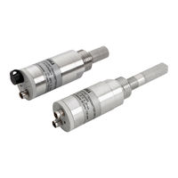
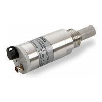
Dew Point Transmitter
Brand:
Vaisala
| Category:
Transmitter
| Size: 2.19 MB
Table of Contents
Table of Contents
3
1 About this Document
9
Version Information
9
Related Manuals
9
Documentation Conventions
9
Table Document Versions (English)
9
Table 2 Related Manuals
9
Trademarks
10
2 Product Overview
11
Introduction to DMT143
11
Table 3 Output Parameters of the DMT143
11
Basic Features and Options
12
Connectivity to Vaisala Insight Software
13
DMT143 and DMT143L Transmitter Parts
14
DMT143 with G1/2" ISO228/1 Thread
14
Figure DMT143 Parts - Model with ISO Thread
14
DMT143 with NPT Thread
15
Figure 2 DMT143 Parts - Model with NPT Thread
15
DMT143L with G1/2" ISO228/1 Thread
16
Loop-Powered Display
16
Figure 3 DMT143L Parts
16
Connection Cables
17
Figure 4 Nokeval 301 Loop-Powered Display
17
Sampling Accessories
18
Safety
18
ESD Protection
18
Regulatory Compliances
19
3 Functional Description
20
Drycapâ Technology
20
Autocalibration
20
Sensor Purge
20
Sensor Warming in High Humidities and Freezing Conditions
21
DMT143 Startup Sequence
21
Alarm LED
22
Figure 5 DMT143 Startup Sequence
22
Table 4 Alarm LED States
22
4 Installation
24
Configuring Transmitter before Installation
24
Selecting the Location
24
Installing the Transmitter
25
Wiring
26
Table 5 Connector Pinouts
26
Figure 6 DMT143 Digital and Analog Connectors
27
Figure 7 Wiring the Digital Connector
27
Figure 8 Wiring the Analog Connector
27
Power Supply Requirements
27
Figure 9 Example of Current Consumption During Purge
28
Sampling from a Process
29
Figure 10 Example of Current Consumption During Autocalibration
29
Sampling Accessories
30
DMT242SC Sampling Cell
30
DMT242SC2 Sampling Cell with Swagelok Connectors
30
DSC74 Sampling Cell with Quick Connector and Leak Screw
31
Figure 11 Sampling Cells DMT242SC2 (Left) and DMT242SC (Right)
31
DSC74B Two-Pressure Sampling Cell
32
Figure 12 DSC74 Sampling Cell with Accessories
32
Figure 13 DSC74B
33
Figure 14 Removing the Leak Screw
34
Figure 15 Default Assembly of DSC74C
35
Figure 16 Alternative Assembly of DSC74C (for Tight Spaces)
36
Figure 17 DM240FA with DMT143
37
5 Operation
38
Transmitter Start-Up
38
Vaisala Insight Software
38
Connecting to Insight Software
39
Operation with DM70 Handheld Dew Point Meter
40
Figure 18 Settings Menu
40
Figure 19 Measurement Settings Menu
40
6 Modbus Communication
42
Table 6 Default Modbus Serial Communication Settings
42
7 Serial Communication
43
Connecting to the Serial Interface
43
Terminal Application Settings
43
Table 7 Default Serial Interface Settings
43
Accessing Serial Interface in Devices with Modbus Output
44
List of Serial Commands
45
Table 8 List of Serial Commands
45
Device Information
46
Show Device Information
46
Show Analog Output Mode
47
Show Firmware Version
47
Show Firmware Information
47
Show Currently Active Errors
48
Show Serial Number
48
Show Command List
48
Table 9 Error Messages on ERRS Command
48
Configuring Analog Output
49
Set Analog Output Parameters and Scaling
49
Set Analog Output Error Notification
50
Extend Analog Output Range
51
Test Analog Output
51
Enable or Disable Analog Output
52
Serial Line Output Commands
52
Start Measurement Output
52
Stop Measurement Output
52
Set Output Interval
52
Output a Reading Once
53
Configuring Measurement Parameters
53
Set Measurement Output Format
53
Table 10 FORM Command Parameters
54
Table 11 FORM Command Modifiers
54
Set Measurement Filtering
55
Set Pressure Compensation Value
56
Select Unit
57
View User Adjustment Parameters
57
Table 12 Pressure Conversion Coefficients
57
Set User Adjustment Parameters
58
Configuring Serial Line Operation
59
Set Serial Line Operating Mode
59
Set Serial Line Settings
59
Table 13 Selection of Output Modes
59
Set Transmitter Address
60
Set Serial Line Response Time
61
Other Commands
61
Opening the Transmitter in POLL Mode
61
Closing the Connection to a Transmitter in POLL Mode
61
Configure the Alarm LED
62
Reset Transmitter
63
Restore Factory Settings
63
8 Maintenance
64
Periodic Maintenance
64
Cleaning
64
Calibration
64
Changing the Filter
64
Field Check Using DM70 Handheld Dew Point Meter
65
Repair Maintenance
67
9 Troubleshooting
68
Solving Typical Problems
68
Table 14 Troubleshooting Table
68
Error Messages in Insight Software
69
Error Codes in MI70 Handheld Meter
69
Table 15 Error Messages in Insight Software
69
Unknown Serial Settings
70
Table 16 Error Codes in MI70
70
10 Technical Data
71
DMT143 Specifications
71
Table 17 Measurement Performance
71
Table 18 Operating Environment
72
Table 19 Inputs and Outputs
72
Table 20 Mechanical Specifications
73
Table 21 Compliance
73
Dimensions
74
Figure 20 DMT143 Dimensions - Model with ISO Thread
74
Figure 21 DMT143 Dimensions - Model with NPT Thread
74
Spare Parts and Accessories
75
Figure 22 DMT143L Dimensions
75
Table 22 Spare Parts and Accessories
75
Appendix A: Modbus Reference
77
Default Communication Settings
77
Function Codes
77
Data Encoding
77
32-Bit Floating Point Format
77
Table 23 Default Modbus Serial Communication Settings
77
Table 24 Modbus Function Codes
77
16-Bit Integer Format
78
Modbus Registers
78
Table 25 16-Bit Signed Integer Format Details
78
Measurement Data Registers
79
Status Registers
79
Table 26 Modbus Measurement Data Registers (Read-Only)
79
Table 27 Modbus Status Registers (Read-Only)
79
A.4.3 Configuration Registers
80
Configuration Registers
80
Table 28 Error Codes on Modbus Interface
80
Table 29 Modbus Configuration Data Registers (Writable)
80
Device Identification Objects
82
Table 30 Modbus Test Registers (Read-Only)
82
Table 31 Device Identification Objects
82
Test Value Registers
82
Modbus Communication Examples
83
Warranty
87
Technical Support
87
Recycling
87
Advertisement
Vaisala DRYCAP DMT143 User Manual (74 pages)
Dewpoint Transmitter
Brand:
Vaisala
| Category:
Transmitter
| Size: 1.46 MB
Table of Contents
Table of Contents
3
Vaisala
3
Chapter 1 General Information
7
About this Manual
7
Contents of this Manual
7
Version Information
8
Related Manuals
8
Documentation Conventions
8
Table 1 Manual Revisions
8
Table 2 Related Manuals
8
Safety
9
ESD Protection
9
Recycling
9
Regulatory Compliances
10
Trademarks
10
License Agreement
10
Warranty
10
Chapter 2 Product Overview
11
Introduction to DMT143
11
Table 3 Output Parameters of the DMT143
11
Basic Features and Options
12
Transmitter Parts
13
Model with G1/2" ISO228/1 Thread
13
Figure 1 DMT143 Parts - Model with ISO Thread
13
Figure 2 DMT143 Parts - Model with NPT Thread
14
Model with NPT Thread
14
Loop-Powered Display
15
Figure 3 Nokeval 301 Loop-Powered Display
15
Connection Cables
16
Sampling Accessories
16
Chapter 3 Functional Description
17
DRYCAP Technology
17
Auto-Calibration
17
Sensor Purge
17
Sensor Warming in High Humidities
18
DMT143 Startup Sequence
19
Figure 4 DMT143 Startup Sequence
19
Alarm LED
20
Table 4 Alarm LED States
20
Chapter 4 Installation
21
Transmitter Configuration before Installation
21
Selecting the Location
22
Installing the Transmitter
22
Figure 5 Removing the Transport Protection Cap
22
Figure 6 Installing the Transmitter with Sealing Ring
23
Figure 7 Tightening with a Wrench
23
Wiring
24
Figure 8 DMT143 Digital and Analog Connectors
24
Figure 10 Wiring the Analog Connector
24
Figure 9 Wiring the Digital Connector
24
Table 5 Connector Pinouts
24
Power Supply Requirements
25
Figure 11 Example of Current Consumption During Purge
26
Figure 12 Example of Current Consumption During Auto-Calibration
27
Sampling Accessories
28
DMT242SC Sampling Cell
28
DMT242SC2 Sampling Cell with Swagelok Connectors
28
DSC74 Sampling Cell with Quick Connector and Leak Screw
29
Figure 13 Sampling Cells DMT242SC2 (Left) and DMT242SC (Right)
29
DSC74B Two-Pressure Sampling Cell
30
Figure 14 DSC74 Sampling Cell with Accessories
30
Figure 15 DSC74B
31
Figure 16 Removing the Leak Screw
31
DSC74C Two-Pressure Sampling Cell with Coil
32
Figure 17 Default Assembly of DSC74C
32
Figure 18 Alternative Assembly of DSC74C (for Tight Spaces)
33
DM240FA Duct Installation Flange
34
Figure 19 DM240FA with DMT143
34
Sampling from a Process
28
Chapter 5 Operation
35
Transmitter Start-Up
35
Operation with DM70 Hand-Held Dewpoint Meter
36
Figure 20 Measurement Settings Menu
36
Serial Communication
37
Connecting to the Serial Interface
37
Installing the Driver for the USB Service Cable
37
Terminal Application Settings
38
Table 6 Default Serial Interface Settings
38
Figure 21 Putty Terminal Application
39
List of Serial Commands
40
Table 7 List of Serial Commands
40
Device Information
41
Show Device Information
41
Show Analog Output Mode
41
Show Firmware Version
42
Show Firmware Information
42
Show Currently Active Errors
42
Show Serial Number
42
Show Command List
43
Configuring Analog Output
44
Set Analog Output Parameters and Scaling
44
Set Analog Output Error Notification
45
Extend Analog Output Range
46
Test Analog Output
46
Enable or Disable Analog Output
47
Serial Line Output Commands
47
Start Measurement Output
47
Stop Measurement Output
47
Set Output Interval
48
Output a Reading Once
48
Configuring Measurement Parameters
49
Set Measurement Output Format
49
Table 8 FORM Command Parameters
50
Table 9 FORM Command Modifiers
50
Set Measured Gas Type
51
Set Measurement Filtering
51
Set Pressure Compensation Value
52
Table 10 Pressure Conversion Coefficients
52
Select Unit
53
View User Adjustment Parameters
53
Set User Adjustment Parameters
54
Configuring Serial Line Operation
55
Set Serial Line Operating Mode
55
Table 11 Selection of Output Modes
55
Set Serial Line Settings
56
Set Transmitter Address
56
Set Serial Line Response Time
57
Other Commands
57
Opening the Transmitter in POLL Mode
57
Closing the Connection to a Transmitter in POLL Mode
57
Configure the Alarm LED
58
Show Transmitter Uptime
59
Reset Transmitter
59
Restore Factory Settings
59
Chapter 6 Maintenance
61
Periodic Maintenance
61
Cleaning
61
Calibration
61
Changing the Filter
62
Figure 22 Removing the Filter
62
Field Check Using the DM70 Hand-Held Dewpoint Meter
63
Chapter 7
64
Repair Maintenance
64
Figure 23 Comparing Dewpoint Readings on MI70
64
Chapter 7 Troubleshooting
65
Solving Typical Problems
65
Table 12 Troubleshooting Table
65
Error Messages
66
Unknown Serial Settings
66
Table 13 Error Messages
66
Technical Support
67
Product Returns
67
Chapter 8 Technical Data
69
Specifications
69
Table 14 Measured Parameters
69
Figure 24 Dewpoint Accuracy Vs. Measurement Conditions
70
Table 15 Operating Environment
70
Table 16 Outputs
70
Table 17 General
71
Spare Parts and Accessories
72
Table 18 Spare Parts and Accessories for DMT143
72
Dimensions in MM
73
Figure 25 DMT143 Dimensions - Model with ISO Thread
73
Figure 26 DMT143 Dimensions - Model with NPT Thread
73
Vaisala DRYCAP DMT143 Manual (16 pages)
DMT143 series with DRYCAP 180D/180M/ 180M sensor
Brand:
Vaisala
| Category:
Transmitter
| Size: 1.12 MB
Table of Contents
General Product Info
1
There Are Two Variants of the DMT143 Transmitter, DMT143 and DMT143L
1
Table of Contents
2
Service Policy
3
Tools Needed
3
Wiring
4
Trouble Shooting
5
Analog Output or Display Does Not Match Expected Value
5
Measurement Reading Bounces Around
5
Checking Error Messages with Service Port
6
Solving Typical Problems
7
Checking Error Messages with Service Port
8
Operational Tests Using USB Service Cable and Service Port
8
Changing Output Parameter and Channel Information
9
Reset to Factory Ordered Configuration
10
Thread Types
10
Maintenance
11
Visual Check
11
Cleaning the HUMICAP Sensor
11
Spare or Replacement Parts Available for Customers
12
Calibration and Adjustment
13
DMT143 Order Codes
15
Calculate Ma and Process Values
16
Advertisement
Advertisement
Related Products
Vaisala HUMICAP DMT132
Vaisala Drycap DMT142
Vaisala Drycap DMT152
Vaisala DMT143L
Vaisala DRYCAP DMT346
Vaisala DRYCAP DMT345
Vaisala DRYCAP DMT342
Vaisala DRYCAP DMT347
Vaisala DRYCAP DMT348
Vaisala DRYCAP DMT344
Vaisala Categories
Transmitter
Measuring Instruments
Accessories
Weather Station
Test Equipment
More Vaisala Manuals
Login
Sign In
OR
Sign in with Facebook
Sign in with Google
Upload manual
Upload from disk
Upload from URL