Sign In
Upload
Manuals
Brands
Vaisala Manuals
Transmitter
DPT146
Vaisala DPT146 Manuals
Manuals and User Guides for Vaisala DPT146. We have
1
Vaisala DPT146 manual available for free PDF download: User Manual
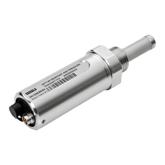
Vaisala DPT146 User Manual (70 pages)
Dewpoint and Pressure Transmitter for Compressed Air
Brand:
Vaisala
| Category:
Transmitter
| Size: 3.44 MB
Table of Contents
Table of Contents
3
Vaisala
3
Chapter 1 General Information
7
About this Manual
7
Contents of this Manual
7
Version Information
8
Related Manuals
8
Documentation Conventions
8
Table 1 Manual Revisions
8
Table 2 Related Manuals
8
Safety
9
ESD Protection
9
Recycling
10
Regulatory Compliances
10
Patent Notice
10
Trademarks
11
License Agreement
11
Warranty
11
Chapter 2 Product Overview
13
Introduction to DPT146
13
Table 3 Output Parameters of DPT146
13
Basic Features and Options
14
Figure 1 DPT146 with ISO G1/2" Thread
14
Transmitter Structure
15
Figure 2 DPT146 Transmitter Structure
15
Connection Cables
16
Figure 3 Cable with Threaded Connector
16
Figure 4 USB Service Cable
16
Loop-Powered Display (Optional)
17
Figure 5 Nokeval 301 Loop-Powered Display
17
Sampling Accessories (Optional)
18
Chapter 3 Functional Description
19
Sensor Technology
19
MPS1 Multiparameter Sensor
19
Figure 6 MPS1 Sensor
19
DRYCAP® Technology
20
Auto-Calibration
20
Sensor Purge
20
Sensor Warming in High Humidities
21
BAROCAP® Technology
21
DPT146 Startup Sequence
22
Figure 7 DPT146 Startup Sequence
22
Chapter 4 Installation
23
Transmitter Configuration before Installation
23
Selecting the Location
24
Installing the Transmitter
24
Figure 8 Removing the Transport Protection Cap
24
Figure 9 Installing the Transmitter
25
Figure 10 Tightening with a Wrench
25
Wiring
26
Figure 11 Connectors I and II
26
Figure 12 Connector Pinout
26
Table 4 Connector Pinouts
26
Sampling from a Process
27
Sampling Accessories
27
DMT242SC Sampling Cell
27
DMT242SC2 Sampling Cell with Swagelok Connectors
27
DSC74 Sampling Cell with Quick Connector and Leak Screw
28
Figure 13 Sampling Cells DMT242SC2 (Left) and DMT242SC (Right)
28
DSC74B Two-Pressure Sampling Cell
29
Figure 14 DSC74 Sampling Cell with Accessories
29
Figure 15 DSC74B
30
Figure 16 Removing the Leak Screw
30
DSC74C Two-Pressure Sampling Cell with Coil
31
Figure 17 Default Assembly of DSC74C
31
Figure 18 Alternative Assembly of DSC74C (for Tight Spaces)
32
DM240FA Duct Installation Flange
33
Figure 19 DM240FA with DPT146
33
Chapter 5 Operation
35
Transmitter Start-Up
35
Serial Communication
36
Connecting to the Serial Interface
36
Installing the Driver for the USB Service Cable
36
Terminal Application Settings
37
Table 5 Default Serial Interface Settings
37
Figure 20 Putty Terminal Application
38
List of Serial Commands
39
Table 6 List of Serial Commands
39
Device Information
40
Show Device Information
40
Show Currently Active Errors
41
Show Command List
41
Show Firmware Version
42
Show Serial Number
42
Configuring Analog Output
42
Set Analog Output Mode
42
Set Analog Output Parameters and Scaling
43
Set Analog Output Error Notification
43
Extend Analog Output Range
44
Test Analog Output
45
Serial Line Output Commands
46
Start Measurement Output
46
Stop Measurement Output
46
Set Output Interval
47
Output a Reading Once
47
Configuring Measurement Parameters
48
Set Measurement Output Format
48
Table 7 FORM Command Parameters
49
Table 8 FORM Command Modifiers
49
Select Unit
50
Configuring Serial Line Operation
50
Set Serial Line Operating Mode
50
Table 9 Selection of Output Modes
50
Set Serial Line Settings
51
Set Transmitter Address
51
Set Serial Line Response Time
52
Other Commands
52
Opening the Transmitter in POLL Mode
52
Closing the Connection to a Transmitter in POLL Mode
53
Show Transmitter Uptime
53
Reset Transmitter
53
Restore Factory Settings
53
Chapter 6 Maintenance
55
Periodic Maintenance
55
Cleaning
55
Changing the Filter
55
Figure 21 Opening the Filter
56
Figure 22 Filter Structure
56
Calibration and Adjustment
57
Field Check Using an MI70 Indicator
57
Figure 23 Comparing Dewpoint Readings on MI70
58
Chapter 7
59
Repair Maintenance
59
Chapter 7 Troubleshooting
61
Solving Typical Problems
61
Table 10 Troubleshooting Table
61
Error Messages
62
Unknown Serial Settings
62
Table 11 Error Messages
62
Technical Support
63
Product Returns
63
Chapter 8 Technical Data
65
Specifications
65
Table 12 Measured Parameters
65
Table 13 Calculated Parameters
65
Table 14 Performance
65
Figure 24 DPT146 Dewpoint Measurement Accuracy
66
Table 15 Operating Environment
66
Table 16 Outputs
66
Table 17 General
67
Spare Parts and Accessories
68
Table 18 DPT146 Spare Parts and Accessories
68
Dimensions in MM
69
Figure 25 DPT146 Dimensions
69
Advertisement
Advertisement
Related Products
Vaisala DPT145
Vaisala DRYCAP DMT143
Vaisala HUMICAP DMT132
Vaisala DRYCAP DMT340 SERIES
Vaisala DRYCAP DMT346
Vaisala DMP248
Vaisala Drycap DMT142
Vaisala Drycap DMT152
Vaisala DMT143L
Vaisala DRYCAP DMT342
Vaisala Categories
Transmitter
Measuring Instruments
Accessories
Test Equipment
Weather Station
More Vaisala Manuals
Login
Sign In
OR
Sign in with Facebook
Sign in with Google
Upload manual
Upload from disk
Upload from URL