Sign In
Upload
Manuals
Brands
SolarEdge Manuals
UPS
Gamatronic B240US
SolarEdge Gamatronic B240US Manuals
Manuals and User Guides for SolarEdge Gamatronic B240US. We have
1
SolarEdge Gamatronic B240US manual available for free PDF download: User Manual
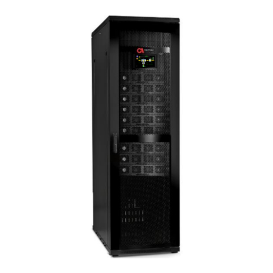
SolarEdge Gamatronic B240US User Manual (198 pages)
THREE PHASE MODULAR UPS FOR THE 480V GRID
Brand:
SolarEdge
| Category:
UPS
| Size: 8.12 MB
Table of Contents
Table of Contents
4
Safety Precautions
14
Do's
14
Don'ts
16
Gamatronic Three Phase Modular Ups for 480Vac
18
System Structure
19
Figure 1: B240 Model, Front View
20
Figure 2: Major Components
21
Figure 3: Connection Terminals (Rear View)
21
Table 1: Key to Figure 2
21
Overview of System Components
22
System Controller
22
A C Power Module (30 Kva / 30 K W)
22
DC Converter Module (60Kw)
23
Static Switch
23
External Battery Bank
23
Overview of Operating Modes
25
Normal Mode
25
Battery Mode
25
Bypass Mode
25
Eco Mode
25
External Manual Bypass Mode
26
Manual) Emergency Power off - Epo
27
Epo Indication
27
Battery Trip Coil Dry Contact
27
Restarting the Ups after Epo
28
Ups Lcd User Interface
29
System Menu (LCD Home) Screen
29
Figure 4: System Menu Screen
29
Table 2: Key to Figure 4
30
System Menu Highlights
31
Operation Menu
31
Figure 5: System Menu, Operation Option
31
Status Menu
32
Figure 6: System Menu, Status Option
32
Figure 7: System Menu, Status Screen
32
Setup Menu
33
Figure 8: System Menu, Setup Option
33
Time
34
Dry Contacts
34
Figure 9: Setup, Time Option
34
Figure 10: Setup, Dry Contacts Option
34
Profile Menu
35
Log Menu
35
Figure 11: System Menu, Profile Option
35
Figure 12: System Menu, Log Option
36
Operating the Ups
37
Turn on UPS
37
Figure 13: Operation, Turn on UPS Option
37
Turn off UPS
38
Turn off Power Modules
38
Turn on Power Modules
38
Figure 14: Operation, Turn off UPS Option
38
Figure 15: Operation, Turn off Power Modules Option
38
Figure 16: Operation, Turn on Power Modules Option
38
Turn on DC Modules
39
Turn off DC Modules
39
Transfer Load to Bypass
39
Transfer Load to Inverter
39
Figure 17: Operation, Turn on DC Modules Option
39
Figure 18: Operation, Turn off DC Modules Option
39
Figure 19: Operation, Transfer Load to Bypass Option
39
Figure 20: Operation, Transfer Load to Inverter Option
39
Battery Test
40
Turn on ECO Mode
40
Turn off ECO Mode
40
Figure 21: Operation, Battery Test Option
40
Figure 22: Operation, ECO Mode on Option
40
Figure 23: Operation, ECO Mode off Option
40
Ups Start-Up/Shutdown
41
Switch on UPS (Not First-Time Start-Up)
41
Figure 24: System Menu, UPS off
41
UPS Total Shutdown (no Ac Output)
43
Figure 25: UPS Is off
43
Ups Menu Functions
44
Figure 26: LCD Control Panel, Displays the System Menu
44
Figure 27: Navigation Trail to the Time Function
44
Figure 28: UPS System Menu
45
Password Requirements
46
Setup Menu
46
Figure 29: Key Icon on Multisystem Mode
46
Setup > SYSTEM
47
Figure 30: Setup Menu
47
Setup > System > NOMINAL SETTINGS
48
Figure 31: Setup > SYSTEM Menu Hierarchy
48
Setup > System > NUMBER of MODULES
49
Redundancy
50
Setup > System > SYSTEM TYPE
50
Multi-System Mode
50
ECO Mode
51
Setup > System > SHUTDOWN and AUTORESTART
51
Setup > System > CONTROLLER
52
Internal Adaptor Status
52
Audio Test
52
Update
52
Figure 32: Shutdown and Auto-Restart Screen
52
Screen Saver Setup
53
Celsius/Fahrenheit
53
Setup > System > MAINTENANCE
53
Maintenance Alarm List
53
Maintenance Alarm Setup
53
Set Last Maintenance Date
53
System Snapshot
53
Start Logging
53
Setup > MODULES
53
Figure 33: Setup > Modules Menu Hierarchy
54
Figure 34: Setup > Modules Menu Options
54
Power Module Ac Input Voltage Calibration
55
Power Module Ac Output Voltage Calibration
56
Figure 35: AC Input Voltage Calibration
56
Power Module Input Current Calibration
57
Figure 36: AC Output Voltage Calibration
57
Power Module Output Current Calibration
59
Figure 37: Modules Input Current Calibration
59
Power Module DC Voltage Calibration
61
Figure 38: Modules Output Current Calibration Screen
61
Figure 39: Modules > DC Voltage Calibration Screen
62
Figure 40: Status > Modules, PFC Status Tab, DC Relay Is on
63
Ac Output Voltage Adjustment
64
Figure 41: DC Voltage Calibration
64
Figure 42: Output Terminals
66
Figure 43: AC Output Voltage Calibration
66
DC Bus Voltage Calibration
68
Figure 44: DC Bus Voltage Calibration
68
Figure 45: DC Bus Terminals
69
DC Voltage Adjustment
70
Figure 46: DC Voltage Adjustment Screen
71
Serial Number
72
Auto Corrrection
73
Figure 47: Serial Number Screen
73
Power Walk-In
74
Figure 48: Auto Correction Screen
74
Setup > DC/DC
75
Figure 49: Power Walk-In Screen
75
Battery Voltage Calibration
76
Figure 50: Setup > DC-To-DC Options
76
Figure 51: Setup, DC-To-DC Menus
76
Figure 52: Battery Bus Bars and Midpoint Bus Bar
77
DC Voltage Calibration
78
Figure 53: Battery Voltage Calibration Screen
78
Figure 54: DC-DC Blocks Numbering Sequence
79
Figure 55: DC Buses
80
Figure 56: DC Voltage Calibration Screen
80
Charger Current Calibration
81
DC-To-DC Voltage Adjustments
82
Boost" Current Calibration
82
Figure 57: Charger Current Calibration Screen
82
Figure 58: DC/DC Voltages Adjustment Screen
82
Adjusting the Battery Voltage (the "Buck" Voltage)
83
Figure 59: Boost Current Calibration
83
Serial Numbers
84
Figure 60: Serial Numbers
84
Setup > BATTERY
85
Figure 61: Setup, Battery Menu Options
85
Setup > Battery > BATTERY TEST PARAMETERS
86
Figure 62: Setup > Battery Menu Hierarchy
86
Figure 63: Battery, Battery Test Menu Options
86
Battery Test Fault Voltage
87
Rectifier Voltage During Battery Test
87
Figure 64: Battery Test Fault Voltage
87
Automatic Battery Test Interval
88
Figure 65: Rectifier Voltage at Battery Test
88
Figure 66: Automatic Battery Test Period
88
Factors that Can Delay the Automatic Battery Test
89
Maximum Duration of Battery Test
89
Next Battery Test Start Time
89
Setup > Battery > BATTERY CURRENT
89
Figure 67: Next Battery Test Start Time
89
Enable/Disable Current Sensors
90
Calibrate Battery Current
90
Figure 68: Setup, Battery, Battery Current
90
Figure 69: Enable/Disable Current Sensors
90
Set DC Current Offset
91
Figure 70: Calibrate Current
91
Set Battery Current Limit Value
92
Figure 71: Set DC Current Offset
92
Minimum DC Voltage at Current Limit
93
Figure 72: Battery Current Limit Value
93
Setup > Battery End-Of-Backup Voltage Limit
94
Figure 73: Minimum DC Voltage at Current Value
94
Setup > Battery > BATTERY CAPACITY in Ah
95
Figure 74: Setup, Battery End of Backup Voltage Limit
95
Setup > Battery > BATTERY TEMPERATURE CONTROL
96
Figure 75: Battery, Battery Capacity
96
Figure 76: Battery, Battery Temperature Control
97
LVD Battery Protector
98
Figure 77: Battery, Temperature Compensation Parameters
98
Figure 78: LVD Battery Protector
99
Figure 79: LVD Battery Protector
100
Setup > STATIC SWITCH
101
Figure 80: Static Switch Menu Options
101
Setup > STSW > CALIBRATE BYPASS VOLTAGE
102
Figure 81: Setup > Static Switch Options
102
Figure 82: Static Switch, Bypass Voltage Calibration
102
Setup > STSW > CALIBRATE OUTPUT VOLTAGE
103
Setup > STSW > CALIBRATE OUTPUT CURRENT
103
Figure 83: Static Switch, Output Voltage
103
Figure 84: Static Switch, Enable Output Current
104
Setup > STSW > HIGH-LEVEL SETUP
105
Setup > STSW > Hi-Level Setup > BYPASS FORCED/CONTROLLED
105
Figure 85: Setup > STSW > High-Level Setup
105
Setup > STSW > Hi-Level Setup > STSW INTEGRATION TIME
106
Setup > STSW > Hi-Level Setup > BYPASS VOLTAGE RANGE
106
Setup > STSW > OVERLOAD HYSTERISIS
106
Setup > STSW > Enable / Disable Analysis Event
106
Figure 86: Static Switch, Overload Hysteresis
106
Setup > STSW > System Type
107
Figure 87: Static Switch, Enable/Disable Analysis Event
107
Figure 88: Static Switch, System Type
107
Setup > ALARMS
108
Figure 89: Setup, Alarms Menu Options
108
Setup > Alarms > SET ALARM PRIORITIES
109
Setup > Alarms > ALARM LIMITS
109
Figure 90: Setup > Alarms Options
109
Figure 91: Alarms > Alarm Limits
110
Setup > Alarms > Alarm Limits > DC VOLTAGE LIMITS
111
Setup > Alarms > Alarm Limits > AC VOLTAGE LIMIT
111
Figure 92: Alarms Limit > DC Voltage Limit Configuration
111
Setup > Alarms > Alarm Limits > Battery Low Limit (Per Battery)
112
Figure 93: Alarm Limits > Ac Voltage Configuration
112
Setup > Alarms > Alarm Limits >TEMPERATURE LIMITS
113
Figure 94: Alarms Limit > Battery Low Limit Voltage
113
Setup > Alarms > ALARMS CONFIGURATION
114
Figure 95: Alarms Limit > Temperature Configuration
114
Setup > CONNECTIVITY
115
Figure 96: Setup, Alarms > Alarms Configuration, Restore Factory Settings
115
Optional) Setup > CONNECTIVITY > NETWORK CONFIGURATION
116
Figure 97: Setup > Connectivity Options
116
Network Configuration Options
117
Network Configuration > OBTAIN IP ADDRESS AUTOMATICALLY
117
Network Configuration > USE STATIC IP ADDRESS
117
Optional Feature) SNMP Configuration Options
117
SNMP Configuration > ACCEPTED COMMUNITY NAMES
117
Figure 98: Setup > Connectivity > SNMP Configuration Options
118
Figure 99: Creating a New Community
118
SNMP Configuration > ACCEPT SNMP PACKETS from THESE HOSTS
119
Figure 100: Community Name Accepted
119
SNMP Configuration > TRAP DESTINATIONS
120
Optional Feature) Setup > Connectivity > Serial Communication
120
Figure 101: Defining Serial Communication Parameters
120
Optional Feature) Modbus
121
Defining a TCP Modbus Link
121
Defining a Serial Modbus Link
121
Optional Feature) Email Configuration
122
Figure 102: Defining Modbus Communication Parameters
122
Figure 103: Example of Email Message Body
123
Figure 104: the Email Configuration Menu
123
Table 3: Description of Email Parameters
124
Adding a New Email Recipient
125
Figure 105: Email Recipients Screen
125
Figure 106: New Email Recipient Screen
125
Figure 107: Alarms Button on Email Recipient Screen
126
Figure 108: Alarm Selection Screen for Email Recipient
126
Controller Host Name
127
Setup > TIME
127
Figure 109: Setup, Time Menu Options
127
Set Date and Time
128
Setup > Time > ADJUST DATE / TIME
128
Figure 110: Setup, Time Options
128
Figure 111: Setup, Time, Adjust Date/Time
128
Setup > Time > CHANGE TIME ZONE
129
Setup > Time > Time Synchronization
129
Setup > Time > SET LAST MAINTENANCE DATE
129
Setup > ASSIGN SITE ID
129
Figure 112: Setup, Time, Time Synchronization
129
Figure 113: Setup > Assign Site ID
130
Figure 114: Assigning a Site ID
131
Optional Feature) Setup > DRY CONTACTS
132
Figure 115: Setup > Dry Contacts Menu
132
Figure 116: Setup > Dry Contacts Option
132
Setup > Dry Contacts > INPUT DRY CONTACTS
133
Location of the Input Dry Contacts
133
Using the Input Dry Contacts
133
Figure 117: Defining an Input Dry Contact
134
Setup > Dry Contacts > OUTPUT DRY CONTACTS
135
Figure 118: Setup > Output Dry Contacts
135
Figure 119: Example of an Output Dry Contact Linked to an Alarm
137
Table 4: Alarms that Can Trigger Output Dry Contacts
137
Location of the Output Dry Contacts
138
Output Dry Contacts in Action
138
Testing an Output Dry Contact
138
Generator Mode Setup
138
Setup > SAVE and RESTORE
139
Setup > Save & Restore > SAVE SETTINGS
139
Figure 120: Generator Mode Setup Screen
139
Figure 121: Setup > Save & Restore Options
139
Setup > Save & Restore > RESTORE SETTINGS
140
Setup > Save & Restore > RESTORE FACTORY SETTINGS
140
Setup > AUTHORIZATION
141
Figure 122: Setup, Authorization
141
Figure 123: Setup > Authorization Option
141
Setup > Authorization > SET USER AUTHORIZATION LEVEL
142
Setup > Authorization > ENABLE / DISABLE REMOTE CONTROL
142
Setup > Authorization > Operations Authorization
142
Figure 124: Setup, Authorizations Operations
142
Operation Menu
143
Figure 125: System Menu > Operation Menu Hierarchy Tree
143
Figure 126: Operation Menu
143
Operation > Turn On/Off > SYSTEM ON/OFF
144
Operation > Turn On/Off > SYSTEM on
144
Operation > Switch On/Off > SYSTEM off
145
Figure 127: Turn Off/On Menu
145
Figure 128: Confirm Dialog, Turn All Modules on
145
Operation > Turn On/Off > MODULES ON/OFF
146
Operation > Turn On/Off > MODULES off
146
Figure 129: Turn Off/On Menu
146
Operation > Switch On/Off > MODULES on
147
Figure 130: Turn On/Off, Modules off
147
Operation > Turn On/Off > CONTROLLER RESTART/SHUTDOWN
148
Figure 131: Turn On/Off, Modules on
148
Operation > Turn On/Off > CONTROLLER RESTART
149
Operation > Turn On/Off > CONTROLLER SHUTDOWN
149
Figure 132: Switch On/Off - Controller Restart
149
Figure 133: Switch On/Off - Controller Shutdown
150
Figure 134: Controller Reset Button on the Back of the Controller
150
Operation > TRANSFER LOAD
151
Operation > Transfer Load > TRANSFER LOAD to INVERTER
151
Figure 135: Operation, Transfer Load to Inverter
151
Operation > Transfer Load > TRANSFER LOAD to BYPASS
152
Figure 136: Operation, Transfer Load to Bypass
152
Operation > BATTERY TEST
153
Figure 137: Transfer Load to Bypass
153
Operation > TURN ECO MODE ON/OFF
154
Figure 138: Operation, Battery Test
154
Figure 139: ECO Mode Screen
155
Figure 140: ECO Mode Screen
157
Figure 141: Reliability Timeouts Screen
158
Figure 142: System, System Type Screen
159
Figure 143: UPS Is ON, but ECO Mode Is Not Turned on
159
Figure 144: UPS Is On, ECO Mode Is Turned on and Inverter Is in Standby State
160
Operation > Firmware Update
161
Figure 145: UPS Is ON, UPS Is on and ECO Mode/Inverter Is in Active State
161
Figure 146: Required System off Warning
162
Figure 147: Select Unit for Update
162
Figure 148: Insert USB Screen
163
Figure 149: USB Port Locations
163
Figure 150: Inverter Update Screen
164
Operation > Calibration Reset
165
Figure 151: PFC Update Screen
165
Figure 152: DC/DC Update Screen
165
Figure 153: System off Warning
166
Figure 154: Calibration Reset
166
Figure 155: Inverter Calibration Reset Screen
167
Figure 156: PFC Calibration Reset Screen
168
Figure 157: DC/DC Calibration Reset Screen
168
Status Menu
169
Figure 158: System Menu > Status Option
169
Figure 159: the Status Screen
169
Table 5: Key to Figure 159 (the Status Screen)
170
Profile Menu
173
Profile > SYSTEM
173
Figure 160: System Menu > Profile Options
173
Figure 161: Profile, System
173
Profile > BATTERY
174
Figure 162: Profile, Battery
174
Profile > STSW
175
Figure 163: Profile, Static Switch
175
Profile > ALARMS
176
Profile > IDENTIFICATION
177
Figure 164: Profile, Identification
177
Log Menu
178
Figure 165: System Menu, Log Options
178
Table 6: Log Message Types (Alarm Types)
178
Figure 166: Log File Contents Listing
179
Figure 167: Log Record - Detailed Display
180
Alarms Button on the Log Detail Screen
181
Figure 168: Alarms Display, from the Log Detail Screen
181
Connectivity Menu
182
Time Menu
182
Figure 169: System Menu, Connectivity Option
182
Figure 170: Connectivity Display from System Menu
182
Language Menu
183
Figure 171: System Menu > Time Option
183
Figure 172: Time Function on the System Menu
183
Figure 173: System Menu > Language Option
183
Periodic Preventative Maintenance
184
Appendix) Holding Registers for Modbus Queries
187
Table 7: Holding Registers for Modbus Queries
187
Advertisement
Advertisement
Related Products
SolarEdge Gamatronic B300
SolarEdge Gamatronic B120US
SolarEdge B60US-IB
SolarEdge StorEdge BI-NUSGN-01
SolarEdge Critical Power B300
SolarEdge L20-IB60, L20-IB00
SolarEdge L30-IB60, L30-IB00
SolarEdge Categories
Inverter
Measuring Instruments
Recording Equipment
UPS
Control Unit
More SolarEdge Manuals
Login
Sign In
OR
Sign in with Facebook
Sign in with Google
Upload manual
Upload from disk
Upload from URL