Sign In
Upload
Manuals
Brands
SolarEdge Manuals
UPS
Gamatronic B120US
SolarEdge Gamatronic B120US Manuals
Manuals and User Guides for SolarEdge Gamatronic B120US. We have
1
SolarEdge Gamatronic B120US manual available for free PDF download: Installation Manual
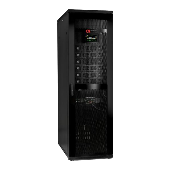
SolarEdge Gamatronic B120US Installation Manual (99 pages)
THREE PHASE MODULAR UPS FOR THE 208V GRID
Brand:
SolarEdge
| Category:
UPS
| Size: 5.29 MB
Table of Contents
Table of Contents
4
1 Unpacking Instructions
9
Figure 1: Inspect the Shipping Crate for Signs of Damage
9
Figure 2: Shockwatch and Tiltwatch Devices
10
Figure 3: Remove the Roof and Support Beams (Use Electric Screwdriver)
11
Figure 4: Remove the Walls of the Crate
11
2 Safety Precautions
13
Do's
13
Don'ts
15
3 System Structure and Installation
16
Figure 5: Major UPS Components (Front View)
16
Figure 6: Main Terminals Viewed from the Ups Rear
18
Table 2: Key to Figure 6
19
Important Installation Information
20
Installation Checklist
21
Installation Procedure
29
Physical Site Preparation
29
Visual Inspection
29
Figure 7: Dimensions of the Gamatronic Ups
31
Electrical Site Preparation
32
Figure 8: Recommended Clearances Around the Ups
32
Table 3: Recommended Clearances
32
Cabling
33
The Ground Line
33
Ac Input and Output Connections
34
The Neutral Line
34
Figure 9: Recommended System Connections
35
Figure 10: Recommended Connections with Input Isolation Transformer
36
Figure 11: Terminal Connections
37
Connecting the UPS to the Electrical Panel
38
Table 4: Recommended Circuit Breakers for the Current Rating for 20-120Kva 208V UPS
38
Assembling and Connecting External Batteries
39
Figure 12: Connecting a Single Battery Set
40
Table 5: Battery Current Ratings for Semiconductor Fuses and Circuit Breakers
40
Figure 13: Connecting Multiple Battery Sets, Using Cbs
41
Table 6: Battery Lifetime Vs Environmental Temp. (Illustrative, as Per Eurobat)
42
Before Starting up the UPS
43
Initial Configuration
43
Powering up the System
43
System Startup Wizard
43
Figure 14: Initial Configuration Wizard
44
Figure 15: Initial Configuration Wizard: Password Entry
45
Figure 16: Initial Configuration Wizard: Battery Capacity in Ah
45
Figure 17: Initial Configuration Wizard: Set Time Zone
46
Figure 18: Exit Configuration Wizard
47
Continuing First Time Startup Process
48
Figure 19: Flat Cables
48
Figure 20: Static Switch
48
Figure 21: Confirm Disconnecting the Load
51
Figure 22: Confirm Switch on All Modules
51
Figure 23: the Alarms Icon Indicates Alarm Conditions
52
Figure 24: Next Scheduled Test Screen
52
Figure 25: Battery Test in Progress Screen
53
Assigning IP Address to the UPS
56
Figure 29: Ip Address Configuration
56
Figure 30: Ip Address Configuration
56
Testing
58
Test: Self-Loading/Pq Mode
58
Figure 31: Enable Pq Mode
59
Figure 32: Pq Mode Setup
59
Figure 33: Pq Mode
59
Figure 34: Reactive Load Testing
61
Figure 35: Disable Pq Mode
61
Test: under Load
61
Test: ATS
62
Test: Battery and Blackout Mode
62
Figure 36: Generator Mode
63
Figure 37: Changing the Auxiliary Contact to Normally Closed
64
Test: ECO Mode
64
Figure 38: Eco Mode Screen - Enabled Checkbox
65
Figure 39: Turning on Eco Mode
66
Figure 40: Status Screen , Ups on and Eco Mode on
66
Test: IP Communication with Controller
67
Figure 41: Web View
68
4 Auxiliary Connections
69
Figure 42: Location of Connector Groups 1 and 2 on the Front of the Ups
69
Table 8: Description of Connector Group 2 (Key to Figure 44)
71
Emergency Power off - EPO (Manual)
74
Restarting the UPS after EPO
74
Input and Output Dry Contacts
74
Lvd Battery Protector
75
Surge Protector Malfunction Alarm
75
Figure 46: Lvd Wiring Diagram
76
5 Circuit Breaker Selectivity
77
Figure 62: a Ups' S Bypass Circuit
77
6 Parallel Operation
79
Theory
79
Decentralized Static Switch Method
79
Parallel Communication
80
Figure 63: the Static Switch in Context ( Stand - Alone System )
80
Figure 50: Parallel Comm
81
Figure 51: Location of the Parallel Comm
81
Common Vs. Decentralized Battery
82
EPO and Parallel Operation
82
Instructions for Parallel Configuration
82
Table 9: Cable Sets for Parallel Communication between Upss
83
Figure 53: Decentralized DC Parallel Communication Cable
84
Figure 52: Common DC Parallel Communication Cable
84
Maintenance Bypass for Parallel Systems
90
Table 10: Rating of CB12 (for Maintenance Bypass Option)
90
7 Procedure: Maintenance Bypass Mode
91
Circuit Breaker Layout
92
Transferring the Ups to Maintenance Bypass Mode from Normal Mode
92
Figure 60: UPS on - Normal Mode
93
Table 11: Normal Mode Operating Position of the Circuit Breakers
93
Figure 61: Transfer Load to Bypass Confirm Dialog
94
Figure 62: Ups on - Bypass Mode
94
Transferring the Ups Back to Normal Mode from Maintenance Bypass Mode
95
Table 12: Position of the Cbs in Maintenance Bypass Mode
95
Table 13: Maintenance Bypass Operating Position of the Circuit Breakers
95
Table 14: Position of the Cbs in Normal Mode
96
8 Using the Ups with a Generator
97
The Automatic Transfer Switch (Ats)
97
Figure 75: Timing Variables When Using a Generator and an Ats
97
Figure 76: Example of an Ats Control Panel
98
9 Service and Repairs
99
Advertisement
Advertisement
Related Products
SolarEdge Gamatronic B300
SolarEdge Gamatronic B240US
SolarEdge B60US-IB
SolarEdge StorEdge BI-NUSGN-01
SolarEdge Critical Power B300
SolarEdge L20-IB60, L20-IB00
SolarEdge L30-IB60, L30-IB00
SolarEdge Categories
Inverter
Measuring Instruments
Recording Equipment
Control Unit
UPS
More SolarEdge Manuals
Login
Sign In
OR
Sign in with Facebook
Sign in with Google
Upload manual
Upload from disk
Upload from URL