Sign In
Upload
Manuals
Brands
Ricoh Manuals
All in One Printer
D042
Ricoh D042 Manuals
Manuals and User Guides for Ricoh D042. We have
2
Ricoh D042 manuals available for free PDF download: Service Manual
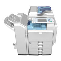
Ricoh D042 Service Manual (1312 pages)
Brand:
Ricoh
| Category:
All in One Printer
| Size: 15.48 MB
Table of Contents
B230/B237/D042
17
Service Manual
1
Table of Contents
17
Paper Feed Unit B800
28
Service Tables
29
Installation
31
Installation Requirements
33
Environment
33
Machine Level
33
Machine Space Requirements
34
Power Requirements
34
Optional Unit Combinations
35
Machine Options
35
Controller Options
36
Copier Installation
37
Power Sockets for Peripherals
37
Installation Flow Chart
38
Accessory Check
39
Installation Procedure
41
Developer and Toner Bottles
42
Paper Trays
43
Emblem and Decals
44
Manual Pocket Attachment
45
Moving the Machine
46
Transporting the Machine
46
Paper Feed Unit (B800)
48
Accessory Check
48
Installation Procedure
48
Lct (B801)
52
Accessory Check
52
Installation Procedure
52
Auto Reverse Document Feeder (B789)
56
Component Check
56
Installation Procedure
60
1-Bin Tray Unit (B790)
60
Component Check
60
Shift Tray Unit (B791)
63
Component Check
63
Installation Procedure
64
Bridge Unit (B227)
66
Component Check
66
Installation Procedure
68
500-Sheet Finisher (B792)
69
Accessory Check
69
Installation Procedure
70
1000-Sheet Finisher (B408)
73
Accessory Check
73
Installation Procedure
74
1000-Sheet Booklet Finisher (B793)
76
Accessory Check
76
Installation Procedure
77
Punch Unit
81
Component Check
81
Installation
82
Mechanical Counter (Na Only)
88
Installation Procedure
88
Installation Procedure
89
Key Counter Bracket
89
Installation Procedure
90
Installation Procedure
93
Anti-Condensation Heater (Scanner)
93
Installation Procedure
94
Tray Heater
94
Controller Options
95
Overview
95
Sd Card Appli Move
96
Move Exec
97
Undo Exec
97
Postscript 3
98
File Format Converter
99
Ieee1394 (Firewire)
100
Ieee1284
102
Ieee 802.11B (Wireless Lan)
103
Bluetooth
106
Copy Data Security Unit
107
Data Overwrite Security Unit Type D (B735)
108
Seal Check and Removal
109
Usb Host Interface
112
Pictbridge
113
Browser Unit Type B
114
VM Card Type C (Java Platform)
115
Check All Connections
116
Remote Communications Gate Installation
117
Fiery E-3000 (B889)
119
Minimum Space Requirements
120
Machine Installation
122
Front and Back Panels
124
Front Panel
124
Preventive Maintenance
139
Settings
141
Before Removing the Old Pm Parts
141
After Installing the New Pm Parts
142
Operation Check
142
Preparation before Operation Check
142
Maintenance Tables
143
Preventive Maintenance Tables
143
Others in Mainframe
148
Replacement and Adjustment
149
Beforehand
151
Special Tools
152
Image Adjustment
153
Scanning
153
Ardf
154
Registration
155
Color Registration
156
Erase Margin Adjustment
156
Printer Gamma Correction
157
Printer Mode
161
Exterior Covers
164
Front Door
164
Left Cover
165
Rear Cover
165
Operation Panel
166
Right Rear Cover
166
Dust Filter
167
Scanner Unit
168
Exposure Glass
168
Exposure Lamp
169
Original Length/Width Sensors
169
Scanner Motor
171
Sensor Board Unit (Sbu)
172
Exposure Lamp Stabilizer
173
Front Scanner Wire
173
Reinstalling the Front Scanner Wire
174
Rear Scanner Wire
176
Touch Panel Position Adjustment
177
Laser Optics
179
Caution Decal Location
179
Laser Optics Housing Unit
179
Before Removing the Old Laser Optics Housing Unit
180
Preparing the New Laser Optics Housing Unit
180
Polygon Mirror Motor
184
Image Creation
186
Drum Unit and Development Unit
186
Pcu
186
Toner Collection Bottle
190
Toner Pump Unit
191
Toner Supply Tube Fan
191
When You Install the New Toner Pump Unit
194
Toner End Sensor
197
Image Transfer
198
Image Transfer Belt Unit
198
Image Transfer Belt Cleaning Unit
199
Image Transfer Belt
200
When Reinstalling the Image Transfer Belt
203
Paper Transfer
205
Paper Transfer Roller Unit
205
Paper Transfer Unit
205
ID Sensor Board
207
Cleaning for ID Sensors
208
Drive Unit
210
Drive Unit Fan
211
Gear Unit
211
Paper Feed Motor
214
Registration Motor
214
Drum/Development Motor-K
215
Fusing/Paper Exit Motor
216
Itb Drive Motor
216
Image Transfer Belt Contact Motor
217
Paper Transfer Contact Motor
217
Duplex Inverter Motor
218
Toner Transport Motor
218
Paper Feed Clutches
219
Toner Collection Unit
219
Drum Motor-Mcy
220
Development Clutch-K
221
Development Motor-Mcy
221
Fusing
222
Fusing Unit
222
Fusing Belt, Pressure Roller, Fusing Lamps
223
When Reassembling the Fusing Unit
227
Heating, Fusing and Tension Roller
228
Lubricant Roller and Cleaning Roller
229
Fusing/Paper Exit Fan
230
Heating Roller Thermistor
231
Heating Roller Thermostats
231
Pressure Roller Thermistor and Thermostat
232
Thermopile
233
Fusing Gear and One-Way Clutch
234
Heating Roller Bearing and Insulating Bushing3-85
235
Pressure Roller Bearing
237
Paper Feed
238
Paper Feed Unit
238
Pick-Up, Feed and Separation Rollers
238
Tray Lift Motor
239
Sensor and Paper End Sensor
240
Registration Sensor
241
By-Pass Paper Size Detection Switch
242
By-Pass Paper Feed Unit
243
Duplex Unit
245
Duplex Transport Motor
245
Electrical Components
247
Controller Box Cover
247
Controller Unit
247
Controller Box
248
Bicu
250
Iob
251
Psu
251
Sio (Scanner In/Out) Board
252
High Voltage Supply Board
253
High Voltage Supply Board Bracket
254
Controller Board
255
Hdd
256
Nvram Replacement Procedure
257
Nvram on the Controller
258
Troubleshooting
261
Process Control Error Conditions
263
Developer Initialization Result
263
Process Control Self-Check Result
264
Vsg Adjustment Result
267
Line Position Adjustment Result
268
Scanner Test Mode
269
Bicu (Ipu) Test Mode
269
Vpu Test Mode
269
Service Call Conditions
271
Sc Code Classification
272
Sc Table
275
Troubleshooting Guide
359
Line Position Adjustment
362
Jam Detection
371
Electrical Component Defects
381
Blown Fuse Conditions
386
Types of Sp Modes
389
Sp Mode Button Summary
390
Selecting the Program Number
391
Switching between Sp Mode and Copy Mode for Test Printing
391
Exiting Service Mode
392
Remarks
393
Copy Service Mode
395
Output Check Table
672
Input Check Table
756
Test Pattern Printing
781
Printer Service Mode
783
Scanner Service Mode
790
Reboot/System Setting Reset
791
Firmware Update
792
Before You Begin
794
Updating Firmware
795
Firmware Update Error
796
Updating the Lcdc for the Operation Panel
797
Downloading Stamp Data
798
Downloading an Sd Card to Nvram
799
Address Book Upload/Download
800
Installing Another Language
801
Handling Firmware Update Errors
803
Sd Card Appli Move
805
Move Exec
806
Undo Exec
807
Controller Self-Diagnostics
808
Detailed Self-Diagnostics
810
Switching on and Setting up Save Debug Log
811
Retrieving the Debug Log from the Hdd
815
New Debug Log Codes
816
Dip Switches
817
Detailed Descriptions
819
Detailed Section Descriptions
821
Paper Path
822
Drive Layout
823
Board Structure
824
Printing Process
826
Process Control
828
Process Control Self Check Procedure
830
Toner Density Adjustment Mode
832
Toner Supply Control
833
Toner Near End/Toner End Detection
834
Developer Initialization
835
Scanning
836
Scanner Drive
837
Original Size Detection
838
Anti-Condensation Heater
839
Image Processing
840
Ipu (Image Processing Unit)
841
Laser Exposure
842
Optical Path
843
Laser Synchronizing Detectors
844
Ld Safety Switch
845
Automatic Line Position Adjustment
846
Adjustment Conditions
847
Main Scan Skew Adjustment
849
Shutter Mechanism
850
Pcu (Photo Conductor Unit)
851
Around the Drum
852
Drum Charge and Quenching
853
Drum Cleaning
854
Development
855
Developer Agitation
856
Development Bias
857
Toner Supply
858
Toner Supply Mechanism
859
Toner Supply from Toner Attraction Pump to Development Unit
860
Toner Cartridge
861
Waste Toner Collection
862
Used Toner Distribution Mechanism
863
Toner Collection Bottle Set/ Near-Full/ Full Detection
864
Image Transfer and Paper Separation
865
Itb Current
867
Transfer Belt Cleaning
868
Transfer Belt Sensor
870
Paper Transfer and Separation
871
Paper Feed
874
Drive – Tray 1, Tray 2, and By-Pass Tray
875
Paper Lift – Trays 1 & 2
876
Paper Size Detection – Trays 1 & 2
877
Paper Height Detection – Trays 1 & 2
878
Paper End Detection – Trays 1 & 2
879
Registration
880
Tray Lock Mechanism
881
Paper Dust Collection
882
By-Pass Paper Size Detection
883
Fusing
884
Fusing Unit Drive
885
Pressure Release Mechanism
886
Fusing Temperatures
887
Overheat Protection
889
Energy Saver Modes
890
Auto off Mode
891
New Unit Detection
892
Paper Exit
893
Junction Gate Mechanism
894
Duplex Unit
895
Duplex Drive
896
Inverter Mechanism
897
Duplex Operation
898
Printer Functions
900
Hard Disk
902
Job Spooling
903
Paper Source Selection
904
Auto Continue
905
Pictbridge
906
Printing Function Description
907
Index Printing
908
Date and File Name Printing
909
Color Matching
912
Paper Type Specification
912
Printing Quality
912
Camera Memo Printing
913
Form Printing
913
Copy Data Security Unit
914
Mask Type for Copying
915
File Format Converter (Mlb)
916
Data Overwrite Security Unit (B735)
917
Overwrite Timing
918
Specifications
921
Printer
925
Scanner
927
Supported Paper Sizes
928
Paper Exit
930
Platen/Ardf Original Size Detection
936
Software Accessories
938
Utility Software
939
Machine Configuration
940
Optional Equipment
944
Paper Feed Unit
945
Sheet Booklet Finisher & Punch Unit
946
Sheet Finisher
947
Sheet Finisher
948
Bridge Unit
949
Bridge Unit Bu3000 B227
953
1 Replacement and Adjustment
957
Bridge Unit Control Board
957
Bridge Unit Drive Motor
958
Tray Exit Sensor
959
Relay Sensor
960
2 Detailed Section Descriptions
961
Mechanical Component Layout
961
Drive Layout
962
Electrical Component Layout
963
Electrical Component Descriptions
964
Junction Gate Mechanism
965
Fax Option B786
969
Important Safety Notices
971
Symbols and Abbreviations
971
1 Installation
973
Fax Unit (B786)
973
Installation Procedure
974
G3 Interface Unit (B787)
979
Component Check
979
Installation Procedure
980
For Installing the Single G3 Board
982
For Installing the Double G3 Boards
983
Fax Unit Option
986
Handset (B433)
986
2 Replacement and Adjustment
988
Fcu
988
3 Troubleshooting
989
Error Codes
989
Ifax Troubleshooting
1004
Ip-Fax Troubleshooting
1006
Cannot Send Via Voip Gateway
1006
Ip-Fax Transmission
1006
Cannot Send by Alias Fax Number
1007
Ip-Fax Reception
1008
Cannot Receive by Alias Fax Number
1009
Cannot Receive by Voip Gateway
1009
4 Service Tables
1011
Beforehand
1011
Service Tables
1012
Sp1-XXX (Bit Switches)
1012
Sp2-XXX (Ram Data)
1013
Sp3-XXX (Tel Line Settings)
1013
Sp4-XXX (Rom Versions)
1015
Sp5-XXX (Initializing)
1015
Sp6-XXX (Reports)
1016
Sp7-XXX (Test Modes)
1018
Sp9-XXX (Design Switch Mode)
1019
Bit Switches
1020
System Switches
1020
I-Fax Switches
1029
Printer Switches
1034
Communication Switches
1039
G3 Switches
1045
G3-2/3 Switches
1052
Ip Fax Switches
1059
Ncu Parameters
1065
Dedicated Transmission Parameters
1077
Fax Parameters
1077
Parameters
1077
Programming Procedure
1077
Service Ram Addresses
1084
5 Detailed Section Descriptions
1094
Overview
1094
Boards
1095
Fcu
1095
Mbu
1096
Sg3 Board
1097
Video Data Path
1099
Memory Transmission and Parallel Memory Transmission
1099
Transmission
1099
Immediate Transmission
1100
Jbig Transmission
1100
Jbig Reception
1101
Reception
1101
Fax Communication Features
1102
Document Server
1102
Multi-Port
1102
Internet Mail Communication
1103
Mail Transmission
1103
Data Formats
1104
Selectable Options
1104
Mail Reception
1105
Secure Internet Transmission
1105
Smtp Reception
1105
Handling Mail Reception Errors
1106
How the Subject Differs According to Mail Type
1108
Subject and Level of Importance
1108
Subjects Displayed on the Pc
1109
Handling Reports
1110
Ip-Fax
1112
What Is Ip-Fax
1112
6 Specifications
1113
General Specifications
1113
Fcu
1113
Capabilities of Programmable Items
1114
Ifax Specifications
1116
Ip-Fax Specifications
1117
Fax Unit Configuration
1118
Ardf Df3000 B789
1121
Symbols Used in this Manual
1123
1 Replacement and Adjustment
1125
Covers and Tray
1125
Front Cover and Original Tray
1125
Rear Cover
1125
Document Feed Components
1126
Original Feed Unit
1126
Pick-Up Roller
1126
Feed Belt
1127
Separation Roller
1128
Electrical Components
1129
Ardf Drive Board and Df Position Sensor
1129
Original Length Sensors and Trailing Edge Sensor
1129
Original Set Sensor
1130
Original Size Sensors and Skew Correction Sensor
1130
Stamp Solenoid and Original Exit Sensor
1131
Original Feed Drive
1132
Feed Motor
1132
Pick-Up Solenoid
1132
Inverter Solenoid
1133
Feed Clutch
1134
Transport Motor
1135
2 Detailed Descriptions
1136
Component Layout
1136
Mechanical Component Layout
1136
Electrical Component Layout
1137
Drive Components
1138
Drive Layout
1140
Basic Operation
1141
Original Set and Size Detection
1141
Mixed Original Size Mode
1142
Pick-Up and Separation
1144
Skew Correction
1145
Original Transport and Exit
1146
Bin Tray
1151
1-Bin Tray B790
1153
Replacement and Adjustment
1157
1-Bin Tray B790
1157
1-Bin Tray Exit Sensor and Led Control Board
1157
Paper Sensor Removal
1157
Detailed Descriptions
1158
Component Layout
1158
Electrical Component Layout
1158
Mechanical Component Layout
1158
Electrical Component Descriptions
1159
Basic Operation
1160
Internal Shift Tray B791
1163
1 Replacement and Adjustment
1167
Tray Cover
1167
Tray Motor and Half Turn Sensor Board
1168
2 Detailed Descriptions
1169
Component Layout
1169
Basic Operation
1170
Finisher Sr3000 B792
1173
Exterior
1177
Main Frame
1177
Front Cover
1177
Rear Cover
1178
Top Cover
1178
Exit Lower Guide
1179
Right Cover
1179
Stapler Unit
1180
Stapler Unit Movement Motor
1180
Jogger Tray Unit
1181
Jogger Motors
1182
Paper Exit Sensor
1183
Pick-Up Roller Contact Motor
1183
Control Board
1184
Paper Transport and Paper Reverse/Exit Motors
1185
Output Tray Unit
1186
Detailed Descriptions
1187
Overall Machine Information
1187
Component Layout
1187
Electrical Component Layout
1189
Detailed Section Descriptions
1191
Output Tray Mechanism
1191
Stack Height Detection
1191
Paper Feed
1193
Jogger Movement
1194
Stapler Unit Movement
1195
Jam Conditions
1196
Error Detection
1197
Booklet Finisher
1199
Booklet Finisher B793
1201
1 Replacement and Adjustment
1205
Covers
1205
Front/Inner/Rear Covers
1205
Upper Covers
1206
Main Body
1208
Positioning Roller
1208
Shift Tray Position Sensor, Upper Limit Switch
1208
Proof Tray Exit / Full Sensor
1209
Finisher Entrance Sensor
1210
Shift Tray Exit Sensor
1211
Shift Tray Motor
1212
Staple Tray Paper Sensor
1212
Entrance Motor
1213
Upper Transport Motor
1213
Lower Transport Motor
1214
Shift Motor
1215
Folder
1216
Staple Folder Unit
1216
Folder Unit
1217
Folder Unit Exit Sensor
1218
Folder Unit Entrance Sensor
1219
Stapler Unit
1219
Others
1230
Main Board
1230
Dip Switches
1231
2 Detailed Section Descriptions
1232
Component Layout
1232
Mechanical Component Layout
1232
Electrical Component Layout
1234
Junction Gates
1243
Proof Tray
1244
Shift Tray
1245
Booklet Tray
1247
Jogger Unit
1250
Stacking for Booklet Stapling
1253
Moving the Stack to the Folding Position
1256
Fold Plate
1257
Fold Rollers
1258
Overview of Operation
1259
Paper Position Detection
1261
Punch Selection and Firing
1262
Punch Unit Movement
1262
Punch Hopper Mechanism
1263
Paper Feed Unit B800
1267
1 Replacement and Adjustment
1271
Rear Cover
1271
Motors and Clutches
1272
Lift Motors
1272
Upper and Lower Paper Feed Clutches
1272
Paper Feed Motor
1273
Main Board
1274
Paper Feed Unit
1275
Pick-Up, Paper Feed and Separation Rollers
1276
Lift, Paper End, and Relay Sensors
1277
2 Detailed Descriptions
1278
Component Layout
1278
Mechanical Component Layout
1278
Electrical Component Layout
1279
Paper Feed
1280
Paper Size Detection
1281
Reverse Roller and Pick-Up Roller Release
1282
Paper Lift
1283
Paper Height and End Detection
1284
Paper Height Detection
1284
Paper End and Bottom Plate
1285
Lcit B801
1289
1 Replacement and Adjustment
1293
Left and Right Tray
1293
Sensors
1294
End Fence Hp Sensor/Paper End Sensor 2
1294
Paper Height Sensors on Paper Storage Side
1294
Changing the Tray Size
1295
Motors
1296
Tray Lift Motor
1296
Tray Motor
1297
Main Board
1298
Clutches
1299
Paper Feed Clutch
1299
Stack Transport Clutch
1299
Paper Feed Unit
1300
Pick-Up, Feed and Separation Rollers
1301
Paper Feed, Paper End, Lift and Relay Sensors
1302
2 Detailed Descriptions
1303
Component Layout
1303
Mechanical Component Layout
1303
Electrical Component Layout
1304
Electrical Component Descriptions
1305
Paper Feed
1307
Separation Roller and Pick-Up Roller Release
1308
Tray Lift
1309
Paper Amount Detection
1310
Paper End Detection (Paper Feed Side)
1311
Paper Stack Transport
1312
Advertisement
Ricoh D042 Service Manual (20 pages)
Brand:
Ricoh
| Category:
All in One Printer
| Size: 0.34 MB
Table of Contents
Service Manual
1
Line Position Adjustment
10
Internal Shift Tray B791
13
Booklet Finisher B793
13
Paper Feed Unit B800
13
Installation
14
Preventive Maintenance
14
Service Tables
14
Detailed Descriptions
14
Specifications
14
Parts Catalog
15
Special Tools
16
Ardf
17
Punch Unit
18
Operation Panel
19
Advertisement
Related Products
Ricoh D045
Ricoh D043
Ricoh D014
Ricoh D015
Ricoh D023
Ricoh D025
Ricoh D010
Ricoh D007
Ricoh D093
Ricoh D029
Ricoh Categories
All in One Printer
Printer
Digital Camera
Copier
Printer Accessories
More Ricoh Manuals
Login
Sign In
OR
Sign in with Facebook
Sign in with Google
Upload manual
Upload from disk
Upload from URL