Sign In
Upload
Manuals
Brands
Ricoh Manuals
Controller
Aficio MP 7001
Ricoh Aficio MP 7001 Manuals
Manuals and User Guides for Ricoh Aficio MP 7001. We have
8
Ricoh Aficio MP 7001 manuals available for free PDF download: Service Manual, Troubleshooting Manual, Manual, Design Manual, Specifications, Control Panel Use Manual
Ricoh Aficio MP 7001 Service Manual (1351 pages)
Brand:
Ricoh
| Category:
Printer
| Size: 55.21 MB
Table of Contents
D062/D063/D065/D066
13
Table of Contents
13
Read this First
25
Laser Safety
26
Product Information
33
Product Information
35
Machine Configuration
36
Guidance for those Who Are Familiar with Predecessor Products
40
Overview
41
Mechanical Component Layout
41
Paper Path (with Cover Interposer Tray)
43
Paper Path (with 9-Bin Mailbox)
44
Drive Layout
45
Specifications
35
Installation
47
Installation Requirements
49
Operating Environment
49
Machine Level
50
Minimum Space Requirements
50
Dimensions
51
Peripheral/Option Summary Table
51
Power Requirements
54
Main Machine
55
Accessory Check
55
Installation Procedure
56
Removing Tapes and Retainers
56
Removing and Filling the Development Unit
59
Re-Installing the Development Unit
62
Initializing the Drum Settings
63
Tandem Tray
64
Machine Level
66
Connecting the Drum Heater Connector and the Tray Heater Connector
67
Date/Time Setting
67
SP Codes
67
Installing the Scanner Heater
68
A3/Dlt Feeder Kit (D482)
70
Accessory Check
70
Installation Procedure
70
Lct (B473)
74
Accessory Check
74
Installation Procedure
74
Removing Tape
74
Installing the LCT
75
Preparing the Main Machine
75
Lg/B4 Feeder Kit (B474)
78
Accessory Check
78
Installation Procedure
79
Multi Folding Unit (D454)
83
Accessories
83
Installation
84
Tapes
84
Ground Plate
85
Paper Guide, Sponge Strip
85
Docking
86
Height Adjustment
88
Power Cord, Breaker Switch Test
88
Proof Tray Auxiliary Plate
89
3000-Sheet Finisher (D460)
91
Accessory Check
96
Installation
97
Jogger Unit (B513)
102
Accessory Check
102
Installation Procedure
102
2000/3000-Sheet Finishers (D373/D374)
105
Installation Procedure
105
Removing Tapes and Retainers
105
Docking the Finisher
107
Attaching the Trays
110
Enabling Booklet Binding (D373 Only)
111
Leveling the Finisher
111
Selecting the Staple Supply Name
111
Auxiliary Trays
112
Punch Unit (B702)
114
Accessories
114
Installation Procedure
114
Cover Interposer Tray (B704)
119
Installation Procedure
119
Removing Tapes and Retainers
119
Attaching the Extensions for the D460
120
Preparing the Finisher (D373/D374/D460)
120
Attach the Extensions to the D460
122
Prepare the Cover Interposer for the D460
122
Attaching the Extensions for the D373/D374
123
Attaching the Corner Plates for the D460
124
Attaching the Interposer Tray (D373/D374/D460)
124
Output Jogger Unit (B703)
128
Accessories
128
Installation Procedure
128
Mail Box (B762)
131
Accessory Check
131
Installation Procedure
131
Copy Tray (B756)
135
Accessories
135
Installation
136
Key Card Bracket (B498), Key Counter Bracket (B452)
138
Key Card Bracket B498 Accessories
138
Key Counter Bracket B452 Accessories
139
Assemble the Key Counter Bracket
140
Install the Key Card Bracket and Assembled Key Counter
140
Installation
140
Installation
143
Copy Connector Kit (B328)
147
Accessories
147
Preparation
147
Installation
148
Usb2.0/Sd Slot Type C (D464)
150
Accessories
150
Installation
150
Mfp Options
155
Merging Applications on One Sd Card
155
Overview
155
Merging Applications
156
Common Procedures
157
Inserting SD Cards
157
Undo Exec
157
Accessories
158
Installation
158
Printer Scanner Unit (D462)
158
Storing Copied SD Cards
158
Accessories
160
Installation
160
Postscript3 Unit (D462-20/22/23)
160
Ieee802.11A/G Interface Unit Type J (D377)
161
Accessories
162
SP Mode Settings for 802.11A/G Wireless LAN
162
Accessory Check
163
File Format Converter Type E (D377)
163
Installation
163
Rev. 08/03/2009
163
Accessory
165
Before You Begin the Procedure
165
Hdd Encryption Unit Type a (D377)
165
Installation Procedure
166
Seal Check and Removal
166
Recovery from a Device Problem
167
Restoring the Encryption Key
167
Accessories
168
Before You Begin
168
Clearing the NVRAM
168
Data Overwrite Security Unit Type H (D377-06)
168
Seal Check and Removal
169
Installation
170
Accessories
172
Browser Unit Type E (D430)
172
Installation
172
Accessories
173
Copy Data Security Unit Type C (B829)
173
After Replacing the Copy Data Security Unit
174
Installation
174
Ipu
174
VM Card (D463)
175
Accessories
176
Ieee1284 (B679)
176
Accessories
178
Gigabit Ethernet Type B (D377)
178
Installation
178
Testing the Sd Card/Usb Slot
180
Preventive Maintenance
182
Pm Tables
184
Replacement and Adjustment
186
General Cautions
188
Drum
188
Drum Unit
188
Replacement and Adjustment
188
Transfer Belt Unit
189
Charge Corona
189
Development
190
Cleaning
190
Fusing Unit
191
Paper Feed
191
Used Toner
191
Special Tools and Lubricants
192
Lubricants
192
Special Tools
192
Operation Panel and External Covers
193
Front Door
193
Operation Panel
193
Right Covers
194
Left Covers
195
Rear Covers
195
Scanner
197
Adf
197
Adf and Top Covers
197
Exposure Glass
198
Top Covers
198
Scanner Original Size Sensors
199
Exposure Lamp
200
Lens Block
200
Siob
201
Scanner Motor
202
Scanner Hp Sensor
203
Scanner Wire Removal
204
Scanner Wire Replacement
204
Scanner Wire Reinstallation and Scanner Position Adjustment
205
Laser Unit
207
Caution Decals
207
Ld Unit, Polygon Motor and Polygon Motor Drive Board
207
Laser Synchronization Detector Replacement
209
SP Adjustments
209
Laser Unit Alignment
210
Drum Unit
212
Development Unit Removal
212
Drum Removal
212
Drum Re-Installation
214
Replacement with a Used Development Unit
214
Charge Corona Unit
215
Charge Corona Wire and Grid
215
Charge Corona Wire Cleaning Pads
217
Opc Drum Removal
217
Dusting the Drum Surface
219
Ptl
220
Drum Potential Sensor
221
Quenching Lamp
221
Cleaning Blade
222
Cleaning Filter
222
Cleaning Brush
223
ID Sensor
224
Pick-Off Pawls
224
Drum Motor
225
Toner Collection Bottle
226
Toner Separation Unit
226
Ozone Filters
227
Internal Dust Filter
228
Optics Dust Filter
228
Toner Cooling Fan
228
Development Unit
230
Developer Replacement
230
Preparation
230
Removal
230
Reinstallation
231
Development Filter
232
Entrance Seal and Side Seals
233
Removal
233
Reinstalling
234
Td Sensor
234
Toner End Sensor
235
Toner Supply Motor
235
Cleaning Requirement
236
Development Motor
237
Transfer Belt Unit
238
Transfer Belt Unit Removal
238
Transfer Belt Removal
239
Re-Installation
240
Transfer Roller Cleaning Blade
241
Discharge Plate
242
Reinstallation
242
Re-Installation
243
Transfer Power Pack
243
Fusing Unit
244
Fusing Unit Removal
244
Fusing Unit Thermistors and Thermostats
245
Reinstallation
246
Web Cleaning Roller
246
Web Unit Disassembly
246
Reinstallation
247
Web Unit Re-Assembly
248
Web Motor and Web End Sensor
249
Fusing Lamps
250
Fusing Lamps, Hot Roller, and Pressure Roller
250
Pressure Roller Cleaning Unit
250
Reinstallation
250
Hot Roller and Pressure Roller
253
Pressure Roller
255
Spring Adjustment
256
Stripper Pawls
256
Nip Band Width Adjustment
257
Fusing Unit Exit Sensor
258
Fusing/Exit Motor
259
Fusing Exit Sensor and Exit Unit Entrance Sensors
260
Duplex Unit
261
Duplex Unit Removal
261
Reinstallation
261
Duplex Unit Side-To-Side Adjustment
262
Jogger Fence Adjustment
262
Duplex Inverter Motor
263
Duplex Motors
263
Duplex Jogger and Transport Motors
264
Duplex Entrance Sensor
265
Duplex Sensors
265
Jogger HP Sensor
265
Duplex Transport Sensor 3
266
Inverter Exit Sensor, Transport Sensors 1 & 2
266
Duplex Jogger Belt Adjustment
267
Paper Feed
269
Paper Tray
269
Tandem Tray
269
Rear Fence Return Sensor Replacement
271
Universal Tray
271
Rear Fence Hp Sensor Replacement
272
Tandem Right Tray Paper Sensor Replacement
272
Bottom Plate Lift Wire Replacement
273
Reinstallation
274
Tandem Tray Paper Size Change
275
Pick-Up, Feed, Separation Roller Replacement
278
Tandem Tray Side Registration
278
Feed Unit
279
For D062/D063
281
For D065/D066
281
Paper Feed Motors
281
Separation Roller Pressure Adjustment
283
Relay Sensor
284
By-Pass Paper Size Detection Board
285
Reinstallation
286
By-Pass Tray Rollers
287
By-Pass Separation Roller Pressure Adjustment
288
Registration Sensor
289
Registration and By-Pass Unit Removal
290
Pcbs and Hdd
292
Cnt Board (Controller Board)
292
Nvram
293
NVRAM on the BCU
293
Reinstallation of CNT Board
293
NVRAM on the Controller
294
Hdd
295
Reinstallation
296
Bcu
297
Ctl-Psu
297
Cnb
299
Pfb
299
Replace the BCU
299
Drb
300
Psu
301
Reinstallation of PSU
301
Adf
302
Adf Covers
302
Feed Belt and Pick-Up Roller
303
Feed Unit
303
Registration Sensor
305
Separation Roller
305
Adf Control Board
307
Original Width, Interval, Separation and Skew Correction Sensors
307
Original Length Sensors
308
Df Position and Aps Sensors
309
Other Adf Sensors
310
Bottom Plate Lift Motor
311
Feed Motor
311
Exit Motor and Transport Motor
312
Cis Unit
313
Pick-Up Roller Motor and Hp Sensor
313
Adf Exit Sensor
314
Adf Transport Belt Assembly
315
Reinstallation
316
Removing the Belt
316
Reinstalling the Belt
318
Reattaching the White Cover
319
Copy Image Adjustments: Printing/Scanning
320
Image Adjustments: Printing
320
Preparation
320
Registration - Leading Edge/Side-To-Side
320
Blank Margin
321
Image Adjustments: Scanning
323
Registration Buckle Adjustment
323
Registration: Platen Mode
323
Magnification
324
Sub Scan Magnification
324
Adf Scanning Adjustments
325
DIP Switch Settings (ADF Main Board)
325
Vertical Black Lines
325
ADF Skew Correction
326
Touch Screen Calibration
328
System Maintenance
330
Service Program Mode
332
General Notes
332
Service Mode Lock/Unlock
332
To Enter and Exit the Service Program Mode
332
Button Selection Entry
333
Direct Entry
333
To Switch to the Copy Window for Test Printing
333
Using the SP Mode
333
Sp Mode Button Summary
334
Sp Mode Print (Smc Print)
335
Resets
336
Memory All Clear: Sp5801
336
Resetting Copy/Document Server Features Only
338
Resetting the System
338
Software and Setting Reset
338
Software Reset
338
Resetting Scanner Features Only
339
Test Pattern Printing
340
Printing Test Pattern: Sp2902-003
340
Test Pattern Table
340
Ipu Front/Back Test Patterns: Sp2902-001,002
342
Test Pattern Table
342
Ipu Printing Test Pattern: Sp2902-004
344
Updating the Firmware
346
Doing the Software Update Procedure
346
Software Update
346
Software Update Procedure
346
Errors During Firmware Update
349
Updating the LCDC for the Operation Panel
350
Downloading Stamp Data
351
Uploading/Downloading Nvram Data
351
Downloading an SD Card to NVRAM
352
Uploading Content of NVRAM to an SD Card
352
Service Program Mode Tables
353
Sp Tables
353
Input/Output Check
354
Using the Debug Log
355
Setting up "Save Debug Log
355
To Switch Debug Log on
355
To Select the Target for the Debug Log File
356
To Select Events
357
To Select One or more Memory Modules for Recording in the Debug Log File
360
More about Debug Log
363
Retrieving the Debug Log from the Hdd
363
SP5857-015: SD to SD (Any)
363
SP5857-016: Make HDD Logfile
363
SP5857-017: Make SD Log File
364
Dip Switch Tables
365
Bcu (Base Engine Control Unit)
365
BCU Base Board DIP SW101
365
Troubleshooting
366
Service Call Conditions
368
Troubleshooting
368
Important Sp Codes
369
Jam Detection
370
Frequent Paper Jams
370
Sensor Locations
370
Program Download
373
Download Error Codes
373
Recovery Methods
373
Timing Charts
379
Feed, Transport, Feed Out: Face-Up
379
Transport, Inverter, Feed Out: Face-Down
380
Duplex Transport
381
Other Problems
383
Blown Fuse Conditions
383
Common Problems
383
Energy Saving
386
Energy Save
388
Energy Saver Modes
388
Timer Settings
388
Recommendation
389
Return to Stand-By Mode
389
Energy Save Effectiveness
390
Paper Save
392
Combine Mode
392
Duplex
392
Effectiveness of Duplex/Combine Function
392
D062/D063/D065/D066 Appendices
398
Type
398
1 Appendix: General Specifications
402
General Specifications
402
Adf
406
Power Consumption
407
Noise Emission
408
Optional Equipment
411
A3/11" X 17" Tray Type 9001 (D482)
411
Rt43 (A4 Lct) (B473)
411
Finisher Sr4050 (3K Finisher D460)
412
Shift Tray
412
Stapler
412
Upper Tray
412
Punch Unit Type 1075 (B531)
413
Output Jogger Unit Type 1075 (B513)
415
Finisher
416
Finisher Sr4030 (3K Finisher D374)
416
Lg Size Tray Type 1075 (B474)
416
Stapler
417
Finisher
418
Finisher Sr4040 (2K Booklet Finisher D373)
418
Stapler
419
D373/D374 Paper Specifications
421
Punch Unit Type 3260 (B702)
422
9-Bin Mailbox (B762)
423
Cover Interposer Tray Type 3260 (B704)
423
General
424
Multi-Folding Unit Fd5000 (D454)
424
Tray Capacity
427
2 Appendix: Pm Tables
432
Pm Tables
432
Around the Drum
434
Main Machine
434
Scanner Optics
434
Development Unit
436
Paper Feed
436
Transfer Belt Unit
437
Fusing Unit and Paper Exit
438
Duplex
439
Adf
440
Optional Peripheral Devices
440
Rt43 (A4 Lct) (B473)
440
Cover Interposer Tray Type 3260 (B704)
441
Finisher SR4050 (3K Finisher D460)
441
(D373)
442
Finisher SR4030 (D374)/ SR4040 (D373)
442
Punch Unit Type 3260 (B702) for Finisher SR4030 (D374)/ SR4040
442
Multi-Folding Unit FD5000 (D454)
443
Related SP Codes
443
3 Appendix: Service Call Conditions
446
Service Call Conditions
446
Service Mode Lock/Unlock
446
Sc Code Descriptions
447
SC100: Scanning System
447
SC200: Exposure
453
SC300: Image Development System (1)
456
SC400: Image Development (2)
464
SC500: Feed, Transport, Duplexing, and Fusing Systems
466
SC600: Data Communication
475
SC700: Peripherals
481
SC800: Overall System
498
SC900: Miscellaneous
511
Additional Sc Codes Printed in Smc Report
517
ADF: Paper Jam Errors
523
Jam Codes
523
Main Unit and LCT (B474): Paper Jam Errors
524
Finisher D373: Jam Codes
526
Finisher D374: Jam Codes
526
Cover Interposer Tray B470: Jam Codes
529
Mailbox B471: Jam Codes
529
Multi-Folding Unit D454: Jam Codes
529
Z-Folding Unit B660 Jam Codes
531
4 Appendix: Service Program Mode Tables
532
Service Program Mode Tables
532
Sp2Xxx Drum
545
Sp3Xxx Processing
571
Sp4Xxx Scanner
575
Sp5Xxx Mode
610
Service Manual
808
Large Capacity Tray
816
Large Capacity Tray B473
818
1 Replacement and Adjustment
820
External Covers
820
Pick-Up/Feed/Separation Rollers
821
Pick-Up Solenoid
822
Paper End Sensor, Upper Cover Switches
823
Tray Motor
824
Paper Stack Sensor
824
Paper Size Adjustment
825
2 Details
826
Overview
826
Lct Main Components
826
Lct Drive Layout
828
Paper Feed and Separation
829
Starting Paper Feed
829
Feed and Separation
830
Paper Lift
831
Paper Height Detection
833
Paper End Detection
834
Output Jogger Unit B513/Punch Unit B531
838
1 Installation
840
2 Preventive Maintenance
841
3 Replacement and Adjustment
842
Door and Cover
842
Front Door
842
Inner Cover
842
Left Inner Cover
842
Side Table and Upper Tray
843
Left Covers
844
Rear Cover and Top Cover
844
Shift Tray
844
Rollers
845
Shift Positioning Roller
845
Positioning Roller
846
Alignment Brush Roller
847
Stack Feed-Out Belt
848
Jogger Fence
849
Sensors
850
Exit Guide Open Sensor
850
Stack Height 1, 2 and Exit Guide Open Sensor
850
Stack Height Sensors 1 and 2
850
Upper Tray Exit Sensor
851
Upper Tray Paper Limit and Exit Sensor
851
Upper Tray Paper Limit Sensor
851
Shift Tray Exit Sensor
852
Entrance and Stapler Tray Entrance Sensors
853
Entrance Sensor
853
Stapler Tray Entrance Sensor
853
Pre-Stack Paper Sensor
854
Staple Waste Hopper Sensor
855
Stapler Rotation Hp and Stapler Return Sensors
856
Stapler
857
Shift Tray Motor
858
Stacking Roller/Roller Drag Motors, Return Hp Sensor
859
Punch Unit B531 (Option)
862
Front to Rear Adjustment
862
Punch Position Adjustment
862
Right to Left Adjustment
862
Jogger Unit B513 (Option)
863
Jogger Unit
863
Jogger Unit Pcb
864
Jogger Unit Motor
865
4 Troubleshooting
866
5 Service Tables
867
Dip Switches
867
Test Points
867
Fuses
867
6 Details
868
Tray and Stapler Junction Gate
868
Paper Pre-Stacking
869
Jogger Unit Paper Positioning
870
Stapler Unit Movement
871
Side-To-Side
871
Rotation (1)
872
Rotation (2)
872
Stapler
873
Feed-Out
875
Paper Exit Stacking
876
Shift Tray
877
Overview
877
Stand-By Mode
877
Shift Tray Up/Down Movement
878
Sort/Stack Mode (Shift Mode)
878
Staple Mode
878
Shift Tray Lower Limit Detection
879
Shift Tray Side-To-Side Movement
880
Jam Conditions
881
Punch Unit B531 (Option)
882
Punch Unit Drive
882
Punch Waste Collection
883
Jogger Unit B513 (Option)
884
Jogger Unit Mechanical Layout
884
Jogger Unit Drive
885
7 Overall Machine Information
886
Mechanical Component Layout
886
Electrical Component Description
887
Drive Layout
890
Advertisement
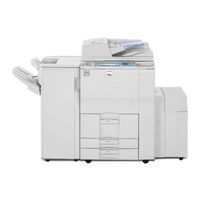
Ricoh Aficio MP 7001 Troubleshooting Manual (160 pages)
Operating Instructions
Brand:
Ricoh
| Category:
All in One Printer
| Size: 9.37 MB
Table of Contents
Operating Instructions
1
Troubleshooting
1
Documentation for this Machine
3
Table of Contents
4
Manuals for this Machine
8
Notice
10
Important
10
How to Read this Manual
11
Symbols
11
Names of Major Items
11
Notes
12
Laws and Regulations
13
Legal Prohibition
13
1 When the Machine Does Not Operate as Wanted
15
Indicators
15
Panel Tone
16
Checking Machine Status and Settings
17
When an Indicator to the Right of a Function Key Is Lit
20
When You Have Problems Operating the Machine
22
When a Job Is Not Performed
26
2 Troubleshooting When Using the Copy/Document Server Function
29
Messages Displayed When Using the Copy/Document Server Function
29
When You Cannot Make Clear Copies
34
When You Cannot Make Copies as Wanted
38
Display During Connect Copy
44
If Connect Copy Is Canceled
45
If You Cannot Exit from Connect Copy
46
When Memory Is Full
47
3 Troubleshooting When Using the Facsimile Function
49
Adjusting the Volume
49
Messages Displayed When Using the Facsimile Function
51
When You Cannot Send or Receive Fax Messages as Wanted
62
When Memory Is Full
68
If an Error Report Is Printed
69
Turning off the Main Power / in the Event of Power Failure
70
When an Error Occurs Using Internet Fax
71
Error Mail Notification
71
Error Report (E-Mail)
71
Server-Generated Error E-Mail
71
4 Troubleshooting When Using the Printer Function
73
Messages Displayed When Installing the Printer Driver
73
Windows 2000
73
Windows XP Professional or Windows Server 2003/2003 R2
73
Windows XP Home Edition
74
Windows Vista
74
Windows Server 2008
75
If USB Connection Fails
76
Messages Displayed When Using the Printer Function
77
Status Messages
77
Messages Displayed on the Control Panel When Using the Printer Function
78
Other Messages
80
Checking the Error Log
87
When You Cannot Print
89
When the Data in Indicator Does Not Light up or Flash
91
Network Connection
92
Other Printing Problems
93
5 Troubleshooting When Using the Scanner Function
103
When Scanning Is Not Done as Expected
103
When You Cannot Send Scanned Files
105
When Stored Files Cannot be Accessed
105
When You Cannot Browse the Network to Send a Scan File
105
When the TWAIN Driver Cannot be Started
105
When Stored Files Cannot be Edited
106
When the Network Delivery Function Cannot be Used
106
When S/MIME Cannot be Used
106
When You Cannot Send Scan Files Using WSD
107
Operations Are Not Possible When Messages Are Displayed
107
Messages Displayed When Using the Scanner Function
109
Messages Displayed on the Control Panel When Using the Scanner Function
109
Messages Displayed on the Client Computer
118
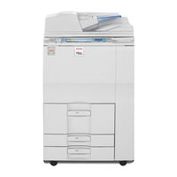
Ricoh Aficio MP 7001 Manual (83 pages)
Security Target
Brand:
Ricoh
| Category:
All in One Printer
| Size: 2.45 MB
Table of Contents
Table of Contents
3
1 ST Introduction
8
ST Reference
8
TOE Reference
8
Table 1: MFP Names for each Series
8
TOE Overview
10
TOE Type
10
TOE Usage and Major Security Features of TOE
10
Environment for TOE Usage and Non-TOE Configuration Items
11
Figure 1: Example of TOE Environment
12
TOE Description
13
Physical Boundary of TOE
13
Figure 2: Hardware Configuration of TOE
14
Guidance Documents
16
User Roles
18
Responsible Manager of MFP
18
Administrator
18
Supervisor
18
Table 2: List of Administrator Roles
18
General User
19
Customer Engineer
19
Logical Boundaries of TOE
19
Basic Functions
20
Figure 3: Logical Boundaries of TOE
20
Security Functions
22
Table 3: Correspondence between Operations Authorised by Permissions to Process Document Data and Operations P Ossible on Document Data
24
Protected Assets
26
Document Data
26
Print Data
26
2 Conformance Claim
27
CC Conformance Claim
27
PP Claims, Package Claims
27
Conformance Rationale
27
3 Security Problem Definitions
28
Threats
28
Organisational Security Policies
28
Assumptions
29
4 Security Objectives
30
Security Objectives for TOE
30
Security Objectives of Operational Environment
31
Security Objectives Rationale
31
Tracing
31
Tracing Justification
32
Table 4: Relationship between Security Environment and Security Objectives
32
5 Extended Components Definition
35
6 Security Requirements
36
Security Functional Requirements
36
Class FAU: Security Audit
36
Table 5: List of Auditable Events
36
Class FCS: Cryptographic Support
41
Table 6: List of Cryptographic Key Generation
41
Class FDP: User Data Protection
42
Table 7: List of Cryptographic Operations
42
Table 8: List of Subjects, Objects, and Operations Among Subjects and Objects
42
Table 9: Subjects, Objects and Security Attributes
42
Table 10: Rules Governing Access
43
Table 11: Rules Governing Access Explicitly
43
Table 12: List of Subjects, Information and Operation
44
Table 13: Security Attributes Corresponding to Subjects or Information
44
Class FIA: Identification and Authentication
45
Table 14: List of Authentication Events
45
Table 15: Lockout Release Actions
45
Class FMT: Security Management
47
Table 16: Rules for Initial Association of Attributes
47
Table 17: Management Roles of Security Attributes
48
Table 18: Characteristics of Static Attribute Initialisation
49
Table 19: List of TSF Data Management
49
Table 20: List of Specifications of Management Functions
51
Class FPT: Protection of the TSF
54
Class FTP: Trusted Path/Channels
54
Table 21: Services Requiring Trusted Paths
55
Security Assurance Requirements
56
Table 22: TOE Security Assurance Requirements (EAL3)
56
Security Requirements Rationale
57
Tracing
57
Table 23: Relationship between Security Objectives and Functional Requirements
57
Justification of Traceability
58
Dependency Analysis
62
Table 24: Correspondence of Dependencies of TOE Security Functional Requirements
62
Security Assurance Requirements Rationale
64
Advertisement
Ricoh Aficio MP 7001 Manual (88 pages)
with DataOverwriteSecurity Unit Type H Security Target
Brand:
Ricoh
| Category:
All in One Printer
| Size: 0.96 MB
Table of Contents
Revision History
2
Table of Contents
3
1 ST Introduction
7
ST Reference
7
TOE Reference
7
Table 1 : Identification Information of TOE
7
TOE Overview
9
TOE Type
9
TOE Usage
9
Figure 1 : Example of TOE Environment
10
Major Security Features of TOE
11
TOE Description
11
Physical Boundary of TOE
11
Figure 2 : Hardware Configuration of the TOE
12
Guidance Documents
14
Table 2 : Guidance for English Version-1
14
Table 3 : Guidance for English Version-2
15
Table 4 : Guidance for English Version-3
16
Table 5 : Guidance for English Version-4
17
Definition of Users
18
Direct User
19
Indirect User
19
Table 6 : Definition of Users
19
Table 7 : List of Administrative Roles
19
Logical Boundary of TOE
20
Basic Functions
20
Figure 3 : Logical Scope of the TOE
20
Security Functions
23
Protected Assets
24
User Data
24
Table 8: Definition of User Data
24
TSF Data
25
Functions
25
Glossary
25
Glossary for this ST
25
Table 9: Definition of TSF Data
25
Table 10: Specific Terms Related to this ST
25
2 Conformance Claim
28
CC Conformance Claim
28
PP Claims
28
Package Claims
28
Conformance Claim Rationale
29
Consistency Claim with TOE Type in PP
29
Consistency Claim with Security Problems and Security Objectives in PP
29
Consistency Claim with Security Requirements in PP
29
3 Security Problem Definitions
32
Threats
32
Organisational Security Policies
33
Assumptions
33
4 Security Objectives
35
Security Objectives for TOE
35
Security Objectives of Operational Environment
36
IT Environment
36
Non-IT Environment
37
Security Objectives Rationale
38
Correspondence Table of Security Objectives
38
Table 11: Rationale for Security Objectives
38
Security Objectives Descriptions
39
5 Extended Components Definition
43
Restricted Forwarding of Data to External Interfaces (FPT_FDI_EXP)
43
6 Security Requirements
45
Security Functional Requirements
45
Class FAU: Security Audit
45
Table 12 : List of Auditable Events
45
Class FCS: Cryptographic Support
48
Table 13 : List of Cryptographic Key Generation
48
Class FDP: User Data Protection
49
Table 14: List of Cryptographic Operation
49
Table 15: List of Subjects, Objects, and Operations Among Subjects and Objects (A)
49
Table 16: List of Subjects, Objects, and Operations Among Subjects and Objects (B)
49
Table 17: Subjects, Objects and Security Attributes (A)
50
Table 18: Rules on User Documents
51
Table 19: Rules on User Jobs (A)
52
Table 20: Rules that Explicitly Authorise Access (A)
52
Table 21: Subjects, Objects and Security Attributes (B)
52
Class FIA: Identification and Authentication
53
Table 22: Rules Governing the Operation for MFP Application (B)
53
Table 23: List of Authentication Events and Unsuccessful Authentication Attempts
53
Table 24: List of Actions for Authentication Failure
54
Table 25: List of Security Attributes for each User that Shall be Maintained
54
Class FMT: Security Management
56
Table 26: Rules for Initial Association of Attributes
56
Table 27: User Roles for Security Attributes (A)
56
Table 28: User Roles for Security Attributes (B)
57
Table 29: Properties of Static Attribute Initialisation (A)
58
Table 30: Authorised Identified Roles Allowed to Override Default Values
59
Table 31: List of TSF Data
60
Table 32: List of Specification of Management Functions
61
Class FPT: Protection of the TSF
62
Class FTA: TOE Access
62
Class FTP: Trusted Path/Channels
63
Security Assurance Requirements
63
Table 33: TOE Security Assurance Requirements (EAL3+ALC_FLR.2)
63
Security Requirements Rationale
64
Tracing
64
Table 34: Relationship between Security Objectives and Functional Requirements
64
Justification of Traceability
65
Dependency Analysis
71
Table 35: Result of Dependency Analysis of TOE Security Functional Requirements
71
Security Assurance Requirements Rationale
73
Ricoh Aficio MP 7001 Design Manual (86 pages)
Design Guide
Brand:
Ricoh
| Category:
Controller
| Size: 0.78 MB
Ricoh Aficio MP 7001 Troubleshooting Manual (23 pages)
Troubleshooting Guide
Brand:
Ricoh
| Category:
All in One Printer
| Size: 0.97 MB
Table of Contents
Troubleshooting
2
Cleaning the Automatic Document Feeder [ADF]
6
Cleaning the Exposure Glass
7
Using the Document Feeder
8
Replacing Toner Cartridges
14
Replacing Toner
15
Clearing Paper Jams
16
Replacing Staples
18
Bypass Tray
20
Meter Reading
22
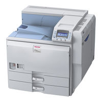
Ricoh Aficio MP 7001 Specifications (6 pages)
Digital Imaging System
Brand:
Ricoh
| Category:
All in One Printer
| Size: 0.64 MB
Ricoh Aficio MP 7001 Control Panel Use Manual (1 page)
Control Panel Instructions
Brand:
Ricoh
| Category:
All in One Printer
| Size: 0.2 MB
Advertisement
Related Products
Ricoh MP 7001SP
Ricoh MP 7001 SP
Ricoh Aficio MP 6001 SP
Ricoh Aficio MP 8001
Ricoh MP 8001SP
Ricoh MP 9001SP
Ricoh AFICIO MP 6001
Ricoh MP 6001 SP
Ricoh MP 9001 SP
Ricoh MP 8001 SP
Ricoh Categories
All in One Printer
Printer
Digital Camera
Copier
Printer Accessories
More Ricoh Manuals
Login
Sign In
OR
Sign in with Facebook
Sign in with Google
Upload manual
Upload from disk
Upload from URL