Sign In
Upload
Manuals
Brands
Immergas Manuals
Boiler
3.024489
Immergas 3.024489 Manuals
Manuals and User Guides for Immergas 3.024489. We have
3
Immergas 3.024489 manuals available for free PDF download: Technical Sheet, Instruction For Technician And Installer, Instructions And Warning Book For The Users
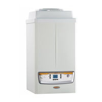
Immergas 3.024489 Technical Sheet (80 pages)
Wall-hung modular condensing boilers for high power
Brand:
Immergas
| Category:
Boiler
| Size: 8.37 MB
Table of Contents
Table of Contents
3
Victrix Pro 35 1 I-55 1 I Specifications
5
Victrix Pro 80 1 I-100 1 I-120 1 I Specifications
6
Victrix Pro 35 1 I-55 1 I Main Parts
7
Victrix Pro 80 1 I-100 1 I-120 1 I Main Parts
8
Victrix Pro 35 1 I-55 1 I Main Measurements
9
Victrix Pro 80 1 I Main Measurements
10
Victrix Pro 100 1 I-120 1 I Main Measurements
11
Hydraulic Kit Measurements and Fittings (Optional) with Single Victrix Pro 35 1 I-55 1 I Boiler
12
Hydraulic Kit Measurements and Fittings (Optional) with Single Victrix Pro 80 1 I-100 1 I-120 1 I Boiler
13
Safety Device Kit for Single Boiler for Victrix Pro 35 1 I - 55 1 I - 80 1 I - 100 1 I - 120 1 I
14
Three-Way Valve Kit for Combination with Separate Storage Tank Unit for Victrix Pro
15
Hydraulic Separator Kit for Individual Boiler Victrix Pro 35 1 I - 55 1 I
16
Hydraulic Separator Kit for Individual Boiler Victrix Pro 80 1 I - 100 1 I - 120 1 I
17
14 Victrix Pro 35 1 I - 55 1 I Adapter Kit in Replacement of the Previous One
18
15 Kit Sizes and Connections (Optional) with Victrix Pro 35 1 I - 55 1 I Boilers
19
In Cascade Configuration (up to a Maximum of Five Appliances)
19
Kit Sizes and Connections (Optional) with Victrix Pro 80 1 I Boilers in Cascade Configuration (up to a Maximum of Five Appliances)
20
Safety Device Kit G 2 1/2" for Boilers in Cascade Configuration Victrix Pro 35 1 I - 55 1 I
22
Safety Device Kit Dn 100 for Boilers in Cascade Configuration Victrix Pro 80 1 I - 100 1 I - 120 1 I
23
Hydraulic Separator Kit Measurements and Fittings (Optional)
24
20 "Free Standing" Supporting Frame Kit (Code 3.024246) for Victrix Pro 1 I
28
Kit Sizes and Connections (Optional) with Victrix Pro 35 1 I - 55 1 I Boilers with
29
Installation on Supporting Frame Set up in Line (up to a Maximum of Five Appliances)
29
Kit Sizes and Connections (Optional) with Victrix Pro 80 1 I - 100 1 I - 120 1 I Boilers with
31
Installation on Supporting Frame Set up in Line (up to a Maximum of Five Appliances)
31
Graph of Victrix Pro 35 1 I - 55 1 I Pump Head Flow Rate
33
Graph of Victrix Pro 80 1 I Pump Head Flow Rate
34
Graph of Victrix Pro 100 1 I Pump Head Flow Rate
35
Graph of Victrix Pro 120 1 I Pump Head Flow Rate
36
Feed Water Treatment
37
Victrix Pro 35 1 I and 55 1 I Wiring Diagram
38
Victrix Pro 80 1 I - 100 1 I and 120 1 I Wiring Diagram
39
Example of Direct Control Without Cascade Regulator Kit of a Booster Pump and
40
A Common Flow Probe
40
Example of Simple Cascade, Without Including the Cascade Regulator (2 Boiler Max.)
41
Victrix Pro 35 1 I - 55 1 I Hydraulic Diagram
42
Victrix Pro 80 1 I - 100 1 I and 120 1 I Hydraulic Diagram
43
Type of Green Range Flue Installation
44
80/125 Ø Concentric Horizontal Kit
45
80/125 Ø Concentric Vertical Kit
46
Vertical Kit for Direct Exhaust
47
Horizontal Terminal Kit for Wall Flue Exhaust
48
Flue Exhaust Manifold Kit 160 Ø with Flue Adjusting Devices Victrix Pro 35 1 I - 55 1 I
49
Flue Exhaust Manifold Kit 200 Ø with Flue Adjusting Devices Victrix Pro 80 1 I - 100 1 I - 120 1 I
50
Th Victrix Pro 100 1 I - 120 1 I
51
Flexible Ducting System
52
Technical Data
53
Combustion Characteristics for Victrix Pro 35 1 I
56
Optional
61
Heat Adjustment Systems (Optional)
64
Cascade and Zone Regulator
65
Cascade and Zone Regulator Diagram of Connections and Terminals
66
Cascade and Zone Regulator/Zone Manager Push Button Panel and Display and Control Screen
67
Zone Manager
68
Modulating Room Thermostat
69
External Probe to Connect to the Boiler
70
Kit for Remote Management
71
Examples of Hydraulic Application Diagrams
74
Advertisement
Immergas 3.024489 Instruction For Technician And Installer (44 pages)
Thermoregulation system
Brand:
Immergas
| Category:
Boiler
| Size: 1.58 MB
Table of Contents
Table of Contents
2
General Safety Devices
4
Regulators Electrical Connection
4
Recommended Diametres and Lenghts for the Cables
5
Zones Manager
6
Installation Place
6
Installation
6
Electrical Connection
7
BUS Address Setting
7
Cascade and Zones Regulator
9
Cascade and Zones Regulator Installation
9
Electrical Installation
9
Cascade Regulator Electrical Connection
10
Zones and Cascade Regulator Start up
11
Code Entering for Parameters Modification
11
AUTO-SET Function
12
Anomalies Signalling
13
Anomalies Register
14
Example of Configuration for the Connection in Cascade
15
Use of the Cascade and Zones Regulator for Installations in Cascade
15
Use of the Cascade and Zones Regulator with a Single Boiler for the Management of Different Heating Circuits
19
Summary of Parameters Setting Levels
21
Hydraulic Level
24
System Parameters Level
27
Domestic Hot Water Level
29
Configuration Level for Direct / Mixed 1 / Mixed 2 Heating Circuits
31
Boiler Configuration Level
33
Cascade Configuration Level
34
BUS Data Configuration Level
34
Solar Configuration Level
35
BUFFER Configuration Level
37
Technical Data
38
Cascade and Zones Regulator
38
Zone Manager
39
Sensors Resistance Values Depending on the Temperature
40
Immergas 3.024489 Instructions And Warning Book For The Users (32 pages)
Cascade and zone regulator Zone manager
Brand:
Immergas
| Category:
Boiler
| Size: 2.92 MB
Table of Contents
Table of Contents
2
Introduction
4
Visualization and Control Elements
4
Operation
5
Keys Function
6
Temperature Settings
6
Operational Mode Selection for Heating and Domestic Hot Water
7
Functions of Operational Modes
8
Setting the Heating Characteristics (Heating Curve)
9
System Information
10
Programming of the Thermoregulation System
12
Programming of Functioning Parameters
12
Programming of Operating Times
14
Copying Operating Times
16
Return Loading of Standard Programs: Deleting of Individual Operating-Times Programs
18
Parameters Configuration
20
Setting of System Parameters (for the Technician)
20
Domestic Hot Water Parameters Setting
23
Heating Circuits Parameters Setting (Direct Circuit, Mixed Circuit 1, Mixed Circuit 2) (for Technician)
24
Time - Date
26
Error Messages
27
Special Operating Modes (for Technician)
28
Emission Measurement
28
Manual Mode (for Technician)
29
Product Specifications
30
Advertisement
Advertisement
Related Products
Immergas 3.024488
Immergas 3.024490
Immergas 3.024491
Immergas 3.024492
Immergas 3.020852
Immergas 3.025615
Immergas 3.025620
Immergas 3.025619
Immergas 3.027746
Immergas 3.027748
Immergas Categories
Boiler
Heat Pump
Boiler Supplies
Water Heater
Controller
More Immergas Manuals
Login
Sign In
OR
Sign in with Facebook
Sign in with Google
Upload manual
Upload from disk
Upload from URL