Ricoh CL7000 Setup Manual
Hide thumbs
Also See for CL7000:
- Operating instructions manual (281 pages) ,
- Maintenance manual (112 pages) ,
- Introduction manual (54 pages)

Related Manuals for Ricoh CL7000


Summary of Contents for Ricoh CL7000
-
Page 1: Setup Guide
Setup Guide Guide to Printer Parts Setting Up Preparing to Print Installing Options For safe and correct use of this machine, please be sure to read the Safety Information in the Setup Guide before you use it. - Page 2 Introduction This manual contains detailed instructions on the operation and maintenance of this machine. To get maximum versatility from this machine all operators should carefully read and follow the instructions in this manual. Please keep this manual in a handy place near the machine. Please read “Safety Information”...
- Page 3 Ethernet is a registered trademark of Xerox Corporation. Bluetooth is a Trademark of the Bluetooth SIG, Inc. (Special Interest Group) and licensed to RICOH Company Limited. Copyright© 2001 Bluetooth SIG, Inc. The Bluetooth Trademarks are owned by Bluetooth SIG, Inc. USA Other product names used herein are for identification purposes only and might be trademarks of their respective companies.
-
Page 4: Safety Information
Safety Information When using your equipment, the following safety precautions should always be followed. Safety During Operation In this manual, the following important symbols are used: R WARNING: Ignoring this warning could cause serious injury or even death. R CAUTION: Ignoring this caution could cause injury or damage to property. - Page 5 R WARNING: • Only connected the machine to the power source described on the inside front cover of this manual. • Avoid multi-wiring. • Do not damage, break or make any modifications to the power cord. Do not place heavy objects on it, pull it hard or bend it more than necessary.
- Page 6 R CAUTION: • Keep the machine away from humidity and dust. A fire or an electric shock might occur. • Do not place the machine on an unstable or tilted surface. If it topples over, it could cause injury. • After you move the machine, fix it with the caster fixture. Otherwise, the machine might move or come down to cause a personal injury.
- Page 7 Note ❒ Disposal should take place at an authorized dealer or an appropriate collec- tion site. An IC2 lithium battery is inside the User Account Enhance Unit. ❒ If you are disposing the User Account Enhance Unit, separate the IC2 lithium battery from the board and dispose of them according to local regulations.
-
Page 8: Energy Star Program
ENERGY STAR Program As an ENERGY STAR Partner, we have determined that this machine model meets the ENERGY STAR Guidelines for energy efficiency. The ENERGY STAR Guidelines intend to establish an international energy-saving system for developing and introducing energy-efficient office equipment to deal with environmental is- sues, such as global warming. -
Page 9: How To Read This Manual
How to Read This Manual Symbols In this manual, the following symbols are used: R WARNING: This symbol indicates a potentially hazardous situation which, if instructions are not followed, could result in death or serious injury. R CAUTION: This symbol indicates a potentially hazardous situation which, if instructions are not followed, may result in minor or moderate injury or damage to property. -
Page 10: Table Of Contents
TABLE OF CONTENTS Trademarks......................i Safety Information ....................ii Safety During Operation..................... ii ENERGY STAR Program ..................vi How to Read This Manual ...................vii 1. Guide to Printer Parts Exterior: Front View....................1 Exterior: Rear View ....................3 Interior........................4 Control Panel......................5 2. - Page 11 Connecting the Cable to the 1394 Interface Unit ............. 50 IEEE 1394 Configuration..................51 USB 2.0 Interface Board Type A ................. 54 Connecting the Cable to the USB 2.0 Interface Board..........56 802.11b Interface Unit Type A................57 IEEE 802.11b (wireless LAN) Configuration ............60 Bluetooth Unit Type 2045..................
-
Page 13: Guide To Printer Parts
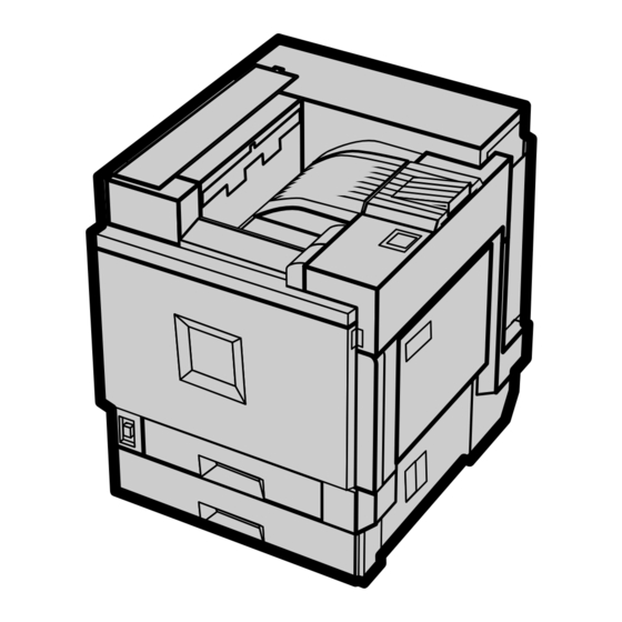
1. Guide to Printer Parts Exterior: Front View Upper cover Tray 2 Remove to install the optional 4-bin mail- Loads up to 500 sheets of plain paper tray box. for printing. Control panel Standard tray Contains keys for printer operation and a Output is stacked here with the print side display to show printer status. - Page 14 Guide to Printer Parts Upper right cover Open this to replace the toner cartridge. Vent This helps keep internal components from overheating. Do not block or ob- struct the vent. Malfunctions may occur due to overheating. Controller board Slide this out to install options such as the memory unit, 1394 interface unit, USB in- terface board, 802.11b interface unit, user account enhance unit or printer hard...
-
Page 15: Exterior: Rear View
Exterior: Rear View Exterior: Rear View ZHXH830N Vent and dustproof filter Power port This helps keep internal components Connect the power cable to this port and from overheating. Do not block or ob- the other end to the wall outlet. struct the vent. -
Page 16: Interior
Guide to Printer Parts Interior ZHXH840J Fusing unit Development unit Fuses the image onto the paper. The printer comes with one black devel- opment unit and three color (yellow, cy- Fuser oil unit an, magenta) development units. Attaches to the fusing unit. Toner cartridge Waste toner bottle Loads from the printer rear, in the order... -
Page 17: Control Panel
Control Panel Control Panel On Line Menu Escape Job Reset Form Feed Enter Power Error Data In Display Power indicator Displays current printer status and error This indicator remains lit while the pow- messages. er is on. It is unlit when the power is off or while the printer is in Energy Saver { { { { Job Reset} } } } key mode. - Page 18 Guide to Printer Parts...
-
Page 19: Setting Up
2. Setting Up Where to Put the Printer The printer's location should be carefully chosen because environmental condi- tions greatly affect its performance. R WARNING: • Confirm the wall outlet is near the machine and freely accessible, so that in the event of emergency, it can be easily unplugged. •... - Page 20 Setting Up ❖ ❖ ❖ ❖ Space Required for Installation Leave enough space around the printer. This space is necessary to operate the printer. The recommended (or minimum) space requirements are as follows: ZDJX005J A: 46 cm (19 inch) or more B: 10 cm (4 inch) or more C: 55 cm (22 inch) or more D: 70 cm (28 inch) or more...
- Page 21 Where to Put the Printer Note ❒ The machine must be level within 5 mm, 0.2” from both front to rear and left to right. ❒ To avoid possible build-up of ozone, locate this machine in a large well ventilated room that has an air turnover of more than 30 m /hr/person.
-
Page 22: Checking The Contents Of The Box
Setting Up Checking the Contents of the Box A A A A Check the box contains the following items. If there are missing items, contact your sales or service representative. ❖ ❖ ❖ ❖ Manuals and CD-ROMs Manuals for This Printer Setup Guide (This manual) Maintenance Guide CD-ROM “Printer Drivers and Utilities”... - Page 23 Checking the Contents of the Box Black Toner Cartridge (K) Magenta (M), Cyan (C), Yellow (Y) Toner Cartridges Paper Feed Unit Labels Additional Documentation Note ❒ This package does not include an interface cable. Please purchase one to use with your host computer. See “Appendix”, Administrator Reference.
-
Page 24: Unpacking
Setting Up Unpacking A A A A E E E E Remove the adhesive tape from Open Tray 2. the printer body. Remove the cardboard taped to the standard tray. ZDJH005J F F F F Remove the adhesive tape and sheet of paper. - Page 25 Unpacking I I I I L L L L Remove the adhesive tape. Remove the securing pin, as shown, from the transfer unit. Pinch it, and then pull it out. ZHXHK110J J J J J Turn the green lever clockwise. ZHXH131J M M M M Close the front cover slowly by...
-
Page 26: Installing The Fuser Oil Unit
Setting Up Installing the Fuser Oil Unit C C C C R CAUTION: Take the fuser oil unit out of the • Keep the fuser oil unit away from bag. Hold the green upper part of flames. There is a risk of fire or seal (A A A A ), and then slowly peel it off. - Page 27 Installing the Fuser Oil Unit D D D D F F F F Close the upper left cover (A A A A ), As shown, hold the fuser oil unit using one hand, and the green and then push the part labeled handle with the other, and then PUSH next to the handle at the bottom rear, until it clicks (B B B B ).
-
Page 28: Installing The Toner Cartridge
Setting Up Installing the Toner Cartridge B B B B R WARNING: Take out the toner cartridges from • Do not incinerate spilled toner the box. or used toner. Toner dust is flammable and will ignite when exposed to an open flame. - Page 29 Installing the Toner Cartridge D D D D F F F F Holding the toner cartridge with Use the same procedure to insert the metal contact area in front, in- the remaining three toner car- sert in the direction of the arrow. tridges.
-
Page 30: Loading Paper
Setting Up Loading Paper This section describes how to load pa- Loading Paper in Tray 1 per in the paper tray. If you do not load paper, the setup procedure will not be properly complete. Important ❒ Tray 1 is 11 × 8 1/2K paper only. The side guide and end guide of each Load only 11 ×... -
Page 31: Loading Paper In Tray 2 And The Optional Paper Feed Unit
Loading Paper B Press the green lever of the side Loading Paper in Tray 2 and guide (A A A A ), and then adjust the po- sition of the guide by moving it in the Optional Paper Feed Unit the direction of the arrow (B B B B ). -
Page 32: 2000-Sheet Large Capacity Tray
Setting Up E E E E A A A A Make sure the paper is fixed in Slowly slide the paper tray out, place, and then lock the side until it stops. guide. ZDJY008J B B B B ZDJY007J Align all four sides of the paper F F F F Slowly slide the paper tray back, stack, and then load two stacks... -
Page 33: Turning The Power On
Turning the Power On Turning the Power On D D D D R WARNING: a ” Turn the power switch to “a • Plug and unplug the power ca- ble with dry hands, or an elec- tric shock could occur. A A A A Make sure the power switch is set b ”... -
Page 34: Selecting The Display Language
Setting Up Selecting the Display Language C C C C Select a language using the procedure Press { { { { Enter #} } } } . described here. The message for the selected lan- guage will appear on the display. Note On Line Menu... -
Page 35: Test Printing
Test Printing Test Printing C C C C Test print in order to check that the Press { { { { U U U U } } } } or { { { { T T T T } } } } to display the printer is working normally. - Page 36 Setting Up...
-
Page 37: Preparing To Print
3. Preparing to Print Connecting the Printer D D D D Connect the other end of the cable Connecting to a Network to the network, such as a hub con- nection. A A A A Turn off the power. For details about network environ- B B B B ment settings, see Administrator Loop the network interface cable... -
Page 38: Parallel Connection
Preparing to Print Parallel Connection Use an interface cable to connect the printer to the computer with a paral- lel connection. The parallel interface cable is not provided with the printer. Note ❒ The printer's parallel connection is a standard bidirectional interface. It requires a standard 36-pin paral- lel cable compliant with IEEE 1284, and a parallel port on the host... -
Page 39: Configuring The Printer For The Network Using The Control Panel
Configuring the Printer for the Network using the Control Panel Configuring the Printer for the Network using the Control Panel A A A A You must make printer settings using Press { { { { Menu} } } } . the control panel to use it in a net- work environment. -
Page 40: Network Setup
Preparing to Print B Press { { { { U U U U } } } } or { { { { T T T T } } } } to display Note “Active Protocol”, and then ❒ Consult your network adminis- press { { { { Enter #} } } } . - Page 41 Configuring the Printer for the Network using the Control Panel G G G G F Press { { { { U U U U } } } } or { { { { T T T T } } } } to set the val- Print the configuration page to ue for the field.
-
Page 42: Installing The Printer Driver
Preparing to Print Installing the Printer Driver B B B B You can install the printer drivers and Select a language for the inter- other software easily using the CD- face, and then click [OK]. ROM labeled “Printer Drivers and The following languages are avail- Utilities”. - Page 43 Installing the Printer Driver D D D D F F F F After reading through the con- Click [Install]. tent, click [I accept the agreement] to The following display appears agree with the License Agree- when installing the printer driver. ment, and then click [Next].
- Page 44 Preparing to Print...
-
Page 45: Installing Options
4. Installing Options Installing Options R CAUTION: • Before installing options, the machine should be turned off, and then un- plugged for at least an hour. Components inside the machine become very hot, and can cause a burn if touched. •... - Page 46 Installing Options Install the 1394 interface unit, USB interface board, 802.11b interface unit or Bluetooth unit on the controller Installing the 1394 interface board. unit, USB 2.0 interface board, 802.11b interface unit or Blue- The 1394 interface unit and the standard Ethernet inter- face cannot be used at the same time.
- Page 47 Installing Options Install options in the positions as shown. ❖ ❖ ❖ ❖ Exterior ZHXH140J Paper Feed Unit Type 3800C (500 SR770 (2 Tray Finisher) × × × × 1) Performs Job Separation, staples and Loads up to 500 sheets (500 sheets × 1 punches holes.
- Page 48 Installing Options Duplex Feed Unit Transports paper during duplex printing. Install the unit inside the printer. See p.77 “Installing the Duplex Rever- sal Unit”. Important ❒ You cannot install the 2 tray finisher unless both the paper feed unit and duplex unit options are attached.
-
Page 49: Using The Screwdriver
Using the Screwdriver Using the Screwdriver The special screwdriver used for attaching options is attached to the inside of the front cover. By pushing the screw top into the screwdriver, you can work with- out having to worry about dropping the screw. ZHXH170J Note ❒... -
Page 50: Paper Feed Unit
Installing Options Paper Feed Unit Preparation Installing the Paper Feed Unit If you want to use the optional du- Type 3800C (500 × × × × 1) plex unit, 2 tray finisher or 4-bin mailbox at the same time, install R CAUTION: the optional paper feed unit first, •... - Page 51 Paper Feed Unit E E E E Important Take out the packaged items, ❒ Four people should hold the making sure there are two thumb screws and one mounting brack- handles, located on two sides of et. Close the tray of the 500-sheet the printer, to move it.
- Page 52 Installing Options I I I I M M M M Open the right cover of the 500- Stick label “3” above the handle sheet paper feed unit. on the front of the 500-sheet paper feed unit. ZHXH860J J J J J ZDJP126J Hook the mounting bracket to the hole, as shown.
-
Page 53: Installing The Paper Feed Unit Type 3800C (500 × 2)
Paper Feed Unit Important Installing the Paper Feed Unit ❒ Four people should hold the Type 3800C (500 × × × × 2) handles, located on two sides of the printer, to move it. R CAUTION: • When moving the paper feed unit, hold the bottom of both sides, and then lift slowly. - Page 54 Installing Options E E E E I I I I Take out the packaged items, Open the right cover of the 1000- making sure there are two thumb sheet paper feed unit. screws and one mounting brack- et. Close the tray of the 1000-sheet paper feed unit firmly.
-
Page 55: Installing The Paper Bank Ps470 (2000-Sheet Large Capacity Tray)
Paper Feed Unit M M M M Stick labels “3” and “4” above the Installing the Paper Bank handles on the front of the 1000- PS470 (2000-sheet Large sheet paper feed unit. Capacity Tray) R CAUTION: • When moving the paper feed unit, hold the bottom of both sides, and then lift slowly. - Page 56 Installing Options F F F F Important Fasten one thumb screw. A coin ❒ Four people should hold the can be used to fasten the screws. handles, located on two sides of the printer, to move it. ZDJP021J G G G G Slowly slide Tray 2 back into the ZDJP007J printer, until it stops.
- Page 57 Paper Feed Unit J J J J ❒ If the paper feed unit is not in- Fasten the bracket with the other stalled properly, repeat the pro- thumb screw. A coin can be used cedure from step . If you to fasten the screws.
-
Page 58: Memory Unit Typec (Sdram Module)
Installing Options Memory Unit TypeC (SDRAM Module) D D D D Important Holding the handle, slowly pull ❒ Before handling the memory unit, out the controller board. grou nd yo urself by tou chin g something metal to discharge any static electricity. - Page 59 Memory Unit TypeC (SDRAM Module) H H H H Note Press the memory unit down until ❒ Be sure to return the provided it clicks into the locked position. screwdriver to its original posi- tion on the inside of the front cover.
-
Page 60: 1394 Interface Unit Type 4510
Installing Options 1394 Interface Unit Type 4510 A A A A Important Check the contents of the box. ❒ Printing using “1394/SCSI Print- ❖ ❖ ❖ ❖ 1394 Interface Unit Type 4510 er” (Windows 2000) device and “IEEE 1394 and SCSI printers” (Windows XP) with the optional 1394 interface unit is possible un- der Windows 2000 and Windows... - Page 61 1394 Interface Unit Type 4510 D D D D Note Remove the two screws fastening ❒ The removed screws will be the controller board to the back of the printer using the provided needed in step screwdriver. H H H H Install the 1394 interface unit into the controller board.
-
Page 62: Connecting The Cable To The 1394 Interface Unit
Installing Options J J J J ❒ If the 1394 interface unit is not Insert the controller board into installed properly, repeat the the top and bottom rails, and then procedure from step . If you slide it in slowly, until it stops. cannot install it properly even after reinstallation, contact your sales or service representative. -
Page 63: Ieee 1394 Configuration
1394 Interface Unit Type 4510 C C C C Press { { { { Enter #} } } } . IEEE 1394 Configuration Use this procedure to configure the printer for use in an IEEE 1394 envi- ronment. The following table shows On Line Menu Escape... - Page 64 Installing Options G G G G ❒ If you press { { { { Escape} } } } when Assign the IP address to the printer. the cursor (k) is in the left- Do not overlap the IP address in most position, the selected IP the same subnet or the same IP ad- address is reset.
- Page 65 1394 Interface Unit Type 4510 M M M M Press { { { { On Line} } } } . “Ready” appears on the display. Ready N N N N Print a configuration page to con- firm the settings made. See p.23 “Test Printing”.
-
Page 66: Usb 2.0 Interface Board Type A
Installing Options USB 2.0 Interface Board Type A A A A A Important Check the contents of the box. ❒ The USB 2.0 interface board sup- ❖ ❖ ❖ ❖ USB 2.0 Interface Board Type A ports a USB connection between the printer and a computer run- ning Windows 98 SE/Me, Win- dows 2000/XP, Mac OS 9.x or Mac... - Page 67 USB 2.0 Interface Board Type A E E E E H H H H Holding the handle, slowly pull Install the USB 2.0 interface out the controller board. board into the controller board. Insert the tip of the USB 2.0 inter- face board into the attachment area (A A A A ), and then push it in the direction of the arrow (B B B B ).
-
Page 68: Connecting The Cable To The Usb 2.0 Interface Board
Installing Options J J J J ❒ If the USB 2.0 interface board is Insert the controller board into not installed properly, repeat the top and bottom rails, and then the procedure from step . If slide it in slowly, until it stops. you cannot install it properly even after reinstallation, contact your sales or service representa-... -
Page 69: 802.11B Interface Unit Type A
802.11b Interface Unit Type A 802.11b Interface Unit Type A • Card Important ❒ Before handling the 802.11b inter- face unit, ground yourself by touching something metal to dis- charge any static electricity. Static electricity can damage the 802.11b interface unit ❒... - Page 70 Installing Options E E E E H H H H Holding the handle, slowly pull Install the 802.11b interface unit out the controller board. into the controller board. Insert the tip of the 802.11b interface unit into the attachment area (A A A A ), and then push it in the direction of the arrow (B B B B ).
- Page 71 802.11b Interface Unit Type A J J J J Note With the label facing down and ❒ Be sure to return the provided the uneven black antenna surface facing up, slowly insert the card screwdriver to its original posi- into the 802.11b interface unit, un- tion on the inside of the front til it stops.
-
Page 72: Ieee 802.11B (Wireless Lan) Configuration
Installing Options B B B B Press { { { { U U U U } } } } or { { { { T T T T } } } } to display “Host IEEE 802.11b (wireless LAN) Interface” menu. Configuration Menu: Configure the printer to use the IEEE... - Page 73 802.11b Interface Unit Type A G G G G K K K K Press { { { { U U U U } } } } or { { { { T T T T } } } } to select the Press the { { { { U U U U } } } } or { { { { T T T T } } } } key to dis- transmission mode.
- Page 74 Installing Options C Continue entering. ❒ If you have entered the WEP key, and then change the set- Note ting, press the { { { { U U U U } } } } or { { { { T T T T } } } } ❒...
- Page 75 802.11b Interface Unit Type A F After entering, press the { { { { Enter #} } } } key. WEP Key: [26] 0000000000000000 The screen returns to step M M M M Press { { { { On Line} } } } . “Ready”...
-
Page 76: Bluetooth Unit Type 2045
Installing Options Bluetooth Unit Type 2045 • Antenna Cap Important ❒ Only Bluetooth-equipped comput- ers support printing with the Blue- tooth unit. ❒ Before handling the Bluetooth in- ZHBPA921E terface unit, ground yourself by B B B B touching something metal to dis- Turn off the power, and then un- charge static electricity. - Page 77 Bluetooth Unit Type 2045 E E E E H H H H Holding the handle, slowly pull Install the Bluetooth unit into the out the controller board. controller board. Insert the tip of the Bluetooth unit into the attach- ment area (A A A A ), and then push it in the direction of the arrow (B B B B ).
- Page 78 Installing Options J J J J M M M M With the side labeled INSERT Press the antenna to extend it. facing up, slowly insert the card into the Bluetooth unit, until it stops. ZHXP030N N N N N Attach the antenna cap over the antenna.
-
Page 79: User Account Enhance Unit Typec
User Account Enhance Unit TypeC User Account Enhance Unit TypeC ❖ ❖ ❖ ❖ One Screw R CAUTION: • Do not place the IC2 lithium bat- tery near or into fire, as it will ex- plode and cause a burn. B B B B •... - Page 80 Installing Options F F F F H H H H Put the controller board down on Tighten the screw fastening the a flat surface. user account enhance unit, using the provided screwdriver. You must install the user account enhance unit in the position as shown.
- Page 81 User Account Enhance Unit TypeC Note ❒ Be sure to return the provided screwdriver to its original posi- tion on the inside of the front cover. ❒ After finishing the installation, you can check the user account enhance unit is installed proper- ly: Print the configuration page from the “List/Test Print”...
-
Page 82: Printer Hard Disk Type 7000
Installing Options Printer Hard Disk Type 7000 ❖ ❖ ❖ ❖ Two Screws Important ❒ Before handling the printer hard disk, ground yourself by touching something metal to discharge any B B B B static electricity. Static electricity Turn off the power, and then un- can damage the printer hard disk. - Page 83 Printer Hard Disk Type 7000 E E E E I I I I Holding the handle, slowly pull Connect the power cable and flat out the controller board. cable to the printer hard disk. ZHXP321J ZDJP025J J J J J F F F F Connect the flat cable to the con- Put the controller board down on...
- Page 84 Installing Options L L L L O O O O Bind the connectors with the Align the controller board with clamp, as shown. the top and bottom rails, and then push in slowly, until it stops. ZHXP360J M M M M ZDJP030J Push the clamp hook back in the P P P P...
-
Page 85: Formatting The Printer Hard Disk Drive
Printer Hard Disk Type 7000 B B B B ❒ After finishing the installation, Press { { { { U U U U } } } } or { { { { T T T T } } } } to display “ you can check the printer hard Maintenance”, and then press disk is installed properly: Print... -
Page 86: Duplex Unit Type 7000
Installing Options Duplex Unit Type 7000 ❖ ❖ ❖ ❖ One Short Screw, Four Long Preparation Screws To use the optional paper feed unit at the same time, install the option- al paper feed unit first, and then in- stall the duplex unit. R CAUTION: •... - Page 87 Duplex Unit Type 7000 B B B B E E E E Remove the adhesive tape and Lift the external tray in the direc- tion of the arrow (A A A A ), and then re- packing materials. move (B B B B ). Important ❒...
- Page 88 Installing Options G G G G I I I I Remove the protective cover on Insert the claws of the stand into the left side of the printer. Hold the holes on the left side of the printer (A A A A ), and then push down the protective cover by both sides, (B B B B ).
-
Page 89: Installing The Duplex Reversal Unit
Duplex Unit Type 7000 C C C C While supporting the duplex re- Installing the Duplex Reversal versal unit, remove the adhesive Unit tape, and then hold the auxiliary bar in front of the hook on the left A A A A side, and then stand it up. - Page 90 Installing Options E E E E This completes installation of the Hang the auxiliary bar on the far duplex reversal unit. Install the left end, as shown, and then install duplex feed unit after the external B B B B the stopper removed in step tray.
-
Page 91: Installing The Duplex Feed Unit
Duplex Unit Type 7000 C C C C Holding the duplex feed unit us- Installing the Duplex Feed Unit ing both hands, place it on the vertical rail, and then slide it A A A A Slowly open the front cover by slowly in until it stops. - Page 92 Installing Options ❒ If the duplex unit is not installed Note properly, repeat the procedure ❒ Be sure to return the provided from step . If you cannot in- screwdriver to its original posi- stall it properly even after rein- tion on the inside of the front stallation, contact your sales or cover.
-
Page 93: Sr770 (2 Tray Finisher)
SR770 (2 Tray Finisher) SR770 (2 Tray Finisher) ❖ ❖ ❖ ❖ Front and Side Preparation Install the 2 tray finisher after the optional paper feed unit, optional memory unit or optional printer hard disk. First, install the options that allow the controller board to be installed, and then the 2 tray finisher. - Page 94 Installing Options D D D D ❖ ❖ ❖ ❖ Interior Slowly open the front cover of the printer, remove the green screw- driver, and then close the cover. Reference p.37 “Using the Screwdriver” E E E E Stand the external tray of the printer.
- Page 95 SR770 (2 Tray Finisher) G G G G J J J J Temporarily fasten one long Holding the mounting bracket screw in the position, as shown. using both hands, move it in the direction of up (A A A A ) to the right Turn the screw three to four times (B B B B ).
- Page 96 Installing Options L L L L Note Temporarily fasten the two long ❒ If you have the 1000-sheet paper screws in the positions shown. Turn the screws three to four feed unit or 2000-sheet Large times by hand. Capacity Tray installed, pro- ceed to step O O O O If you have the 500-sheet paper feed...
- Page 97 SR770 (2 Tray Finisher) Q Q Q Q T T T T Fasten the rails using a long screw Connect the cable of the 2 tray fin- and the provided screwdriver. isher to the lower connector on the back of the printer. ZDJP078J R R R R Slowly push the 2 tray finisher to-...
- Page 98 Installing Options V V V V B With the 2 tray finisher tray Put the finisher tray installed on laid horizontally, slide it in at a the duplex unit back in place. slant until it stops. A Lift the top. ZDJP083J ZHXH360J C Fasten the finisher tray using a...
-
Page 99: Mail Bin Type 3800C (4-Bin Mailbox)
Mail Bin Type 3800C (4-bin Mailbox) Mail Bin Type 3800C (4-bin Mailbox) Preparation Important ❒ Do not remove the adhesive If you want to use the optional pa- per feed unit at the same time, in- tape fastening the cable yet. Re- stall the optional paper feed unit move it in step first, and then install the 4-bin... - Page 100 Installing Options G G G G There is an opening for installing Pull up the external tray in the di- the 4-bin mailbox. rection of the arrow (A A A A ), and then remove (B B B B ). ZDJP089J ZDJP777J Note...
- Page 101 Mail Bin Type 3800C (4-bin Mailbox) I I I I L L L L Open the upper left cover. Install the external tray into the printer. Hook the external tray the printer's slits, and then lower the tray toward you. ZHXH390J J J J J Fasten the 4-bin mailbox using...
- Page 102 Installing Options O O O O Note Check the cable of the 4-bin mail- ❒ If you have decided to assign box is in position, as shown. mail box bins to individuals and If it is not, change its position in the departments, write their names direction of (A) ⇒...
-
Page 103: Index
INDEX Frame type NetWare , 27 1394 Interface Unit Type 4510 , 48 Front Cover , 1 4-bin Mailbox/2 Tray Finisher Port , 3 Fuser Oil Unit , 4 , 14 802.11b Interface Unit Type A , 57 Fusing Unit , 4 Access Control Address , 27 Gateway Address , 27 Access Control Mask , 27... - Page 104 Paper Bank PS470 (2000-sheet Large Vent , 1 Capacity Tray) , 20 , 35 , 43 Vents , 3 Paper Feed Unit Type 3800C (500 × 1) , 19 , 35 , 38 Paper Feed Unit Type 3800C (500 × 2) , 19 , Warning , ii 35 , 41 Waste Oil Bottle , 4...
- Page 105 Network interface cable with ferrite core must be used for RF interference suppression. Declaration of Conformity Product Name: Laser Printer Model Number: Aficio CL7000/CLP28/DSc38u/LP138c Responsible party: Ricoh Corporation Address: 5 Dedrick Place, West Caldwell, NJ 07006 Telephone number: 973-882-2000 This device complies with part 15 of FCC Rules.
- Page 106 EN USA G080-6900...