
Related Manuals for Samsung CE957GR


Summary of Contents for Samsung CE957GR
-
Page 1: Table Of Contents
MICROWAVE OVEN CE957GR SERVICE Manual CONTENTS MICROWAVE OVEN 1. Precaution 2. Specifications 3. Operating Instructions 4. Disassembly and Reassembly 5. Alignment and Adjustments 1-2-3 6. Troubleshooting 1min+ 7. Exploded Views and Parts List 8. PCB Diagrams 9. Schematic Diagrams SRSC... -
Page 2: Precaution
16. Always connect a test instrument's ground 10. Service technicians should remove their watches while repairing an MWO. lead to the instrument chassis ground before connecting the positive lead; always remove the instrument's ground lead last. Samsung Electronics... - Page 3 Servicemen should remove their watches whenever DO NOT measure the voltage in the high voltage circuit working close to or replacing the magnetron. including filament voltage of magnetron. Samsung Electronics...
-
Page 4: Specifications
2. Specifications 2-1 Table of Specifications MODEL CE957GR ITEM TIMER 99 MINUTES 90 SECONDS POWER SOURCE 230V/50HZ, AC POWER CONSUMPTION MICROWAVE : 1,500W,GRILL : 1,300W OUTPUT POWER FROM90 TO 900W (10 LEVEL POWER) (IEC-705 TEST PROCEDURE) OPERATING FREQUENCY 2,450MHz MAGNETRON... -
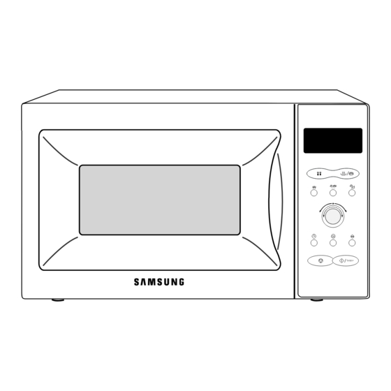
Page 5: Operating Instructions
More/Less Button Memory Button 1min+ Stop/Cancel Button Start Button 3-2 Features & External Views Ventilation Holes Light Door Safety Interlock Holes 1-2-3 Control Panel 1min+ Glass Plate Guide Roller Door Latches Grill Rack 1-2-3 1min+ 216.4mm 369mm 517mm 433mm Samsung Electronics... -
Page 6: Disassembly And Reassembly
4-2 Replacement of High Voltage Transformer 1. Discharge the high voltage capacitor. 2. Disconnect all the leads. 3. Remove the mounting bolts. 4. Reconnect the leads correctly and firmly. Bolts H. V. Trans Samsung Electronics... -
Page 7: Replacement Of Door Assembly
1. Insertion depth of the thin metal plate should be 0.5mm or less. 4-3-4 Removal of Key Door & Spring Door "E" Remove pin hinge from Door "E" Detach spring from Door "E" and key door. Key Door Spring Samsung Electronics... -
Page 8: Replacement Of Fuse/Drive Motor
Switch coupler. 8. Connect all the leads to the drive motor. Drive Motor Cover Base Plate 9. Screw the drive motor cover to the base plate with a screw driver. Samsung Electronics... - Page 9 2. Disconnect the connectors from the control circuit board. 3. Remove screws securing the control circuit bord. 4. Lift up the control circuit board from right side and remove the hooks holding the contol circuit board to the box assembly. SCREWS Samsung Electronics...
-
Page 10: Alignment And Adjustments
2. Isolate the magnetron from the circuit by disconnecting its leads. 3. A continuity check across the magnetron filament terminals should indicate one ohm or less. 4. A continuity check between each filament terminal and magnetron case should read open. Cooling Fins Samsung Electronics... -
Page 11: High Voltage Capacitor
Door Open Door Closed procedures. ∞ Primary switch 5. Confirm that the gap between the switch ∞ Monitor switch (COM-NC) housing and the switch actuator is no more than ∞ Door Sensing S/W 0.5mm when door is closed. Samsung Electronics... - Page 12 5. After heating for 2 minutes, measure the water temperature in each beaker. 6. Microwave heat distribution rate can be calculated as follows: Minimum Beaker Temperature Rise Heat Distribution = X 100(%) Maximum Temperature Rise The result should exceed 65%. Cooking Tray Samsung Electronics...
-
Page 13: Procedure For Measurement Of Microwave Energy Leakage
; CENTRAL SERVICE CENTER 5-13-2 At least once a year have the microwave energy survey meter checked for accuracy by its manufacturer. Samsung Electronics... -
Page 14: Troubleshooting
H.V.Transformer component test procedure and replace if it is H.V.Capacitor defective. H.V.Diode,H.V.Fuse Magnetron 4. Open or loose wiring of power relay 5. Defective primary latch switch 6. Defective power relay or Ass'y PCB Replace PCB main. Samsung Electronics... - Page 15 Use plastic wrap or cover with a lid. Stir once or twice while cooking foods such as soup, cocoa, or milk. Noise from the turntable motor Noise may result from the motor. Replace turntable motor. when it starts to operate. Samsung Electronics...
-
Page 16: Exploded Views And Parts List
7. Exploded Views and Parts List 7-1 Exploded Views M8 M9 Samsung Electronics... -
Page 17: Main Parts List
FOOT PP(A353),BLK,MW5630T DE80-10001A BASE-PLATE SGCC,T0.8,345,565 DE31-10154A MOTOR-DRIVE M2HJ49ZR02,ST-16,50/60HZ DE71-60382A COVER-CEILING MICASHEET,T0.5,70,133 DE71-60016A COVER-AIR PP,2,WHT,M945/M245 4713-001031 LAMP-INCANDESCENT 230V,173mA,40W,ORG,-,-,25x69mm DE93-30416L ASSY CONTROL-BOX CE957GR/BWT DE92-40178D ASSY DOOR HANDLE,WHT,NO-VITALITY DE61-30006A SUPPORTER-HEATER ALUMINA,5G,2ND-W/P DE61-70060A SPRING-PLATE SK-5,T0.5 DE61-50490A BRACKET-TCO SECC1,T0.6,34,58 OM75PH(31)ESS ASSY-MAGNETRON OM75PH(31)ESS DE47-20009A THERMOSTAT PW2N-520PB,160/60,250V/7.5A,H,... -
Page 18: Door Parts List
0.8,0,36,6,BLUING,-,- DE61-80002A HINGE-UPPER SCP1,T2.3,26,77,ZPC3,WHT,CE945 DE61-80003A HINGE-LOWER SCP1,T2.3,26,77,ZPC3,WHT,CE945 7-3 Control Parts List Ref. No. Parts No. Description Specification Q'ty Remarks RC-957G-04 ASSY PCB PARTS MWO,CE957GR,230V50HZ DE72-70182P CONTROL-PANEL ABS,-,-,-,WHT,170G,CE957GR/BWT DE67-40147A WINDOW-DISPLAY ACRYL,SMOG,M757/CE757G DE66-20183B BUTTON-SELECT-B ABS(HR-0370D),WHT,M757(SDW/SKW DE66-20185A BUTTON-SELECT-A ABS,WHT,M757/CE757G DE66-20184A BUTTON-SELECT-C ABS(HR-0370D),WHT,M757(SKW,SDW DE64-10128A... -
Page 19: Standard Parts List
DE60-10122A SCREW-TAP TH TAP,TH,2-4X8,FE,FN C-CEIL DE60-20063A BOLT-FLANGE M4,10,ZPC3,YEL,MSWR HI-LOW DE60-20063A BOLT-FLANGE M4,10,ZPC3,YEL,MSWR HI-UPP DE60-10045A SCREW-TAP PH PH,M3,L6,FEFZY B-TCO DE60-10098A SCREW-ASSY TAP TITE PH,TC,M4X8,SWRCH18A,ZPC2,GLD,W B-HVC DE60-10012A SCREW-TAP TITE TH,+,3,M4,L10,SWR10,ZPC2,TOOTH B-PLATE DE60-10088A SCREW-TAP PH PH,M3,L8,FEFZY,PLAIN DE60-10045A SCREW-TAP PH PH,M3,L6,FEFZY GUIDE-AIR Samsung Electronics... - Page 20 8. P.C.B Diagrams 8-1 P.C.B Diagrams Samsung Electronics...
- Page 21 SWITCH-TACT 15V,20mA,130°æ40gf,6x6x5mm,SPS SW18 3711-000203 CONNECTOR-HEADER 1WALL,3P,1R,3.96MM,STRAIGHT,SN CN01 3711-000240 CONNECTOR-HEADER 1WALL,4P,1R,3.96mm,STRAIGHT,SN CN02 3711-000881 CONNECTOR-HEADER BOX,3P,1R,2.5mm,STRAIGHT,SN CN03 DE13-20009A KA7533,DIP IC02 DE39-60001A WIRE-SO COPPER PI0.6,SN,T,52MM,TAPING_WIRE J01,J02,J03,J04,J05 DE39-60001A WIRE-SO COPPER PI0.6,SN,T,52MM,TAPING_WIRE J06,J07,J08,J09,J10 DE39-60001A WIRE-SO COPPER PI0.6,SN,T,52MM,TAPING_WIRE J11,J12,J13,J14,J15 DE39-60001A WIRE-SO COPPER PI0.6,SN,T,52MM,TAPING_WIRE J16,J27,J28 Samsung Electronics...
-
Page 22: Schematic Diagrams
YEL : YELLOW BLK : BLACK BLK BLK Y/G : YELLOW GREEN PRIMARY LATCH DOOR SENSING MONITOR SWITCH SWITCH SWITCH MAGNETRON HIGH VOLTAGE DIODE TO CHASSIS HIGH VOLTAGE CAPACITOR H.V.FUSE SYMBOL COLOR BROWN BLACK BLUE HIGH VOLTAGE TRANSFORMER Samsung Electronics...