
Related Manuals for Samsung M245


Summary of Contents for Samsung M245
-
Page 1: Table Of Contents
MICROWAVE OVEN M245 SERVICE Manual MICROWAVE OVEN CONTENTS 1. Precaution 2. Specifications 3. Operating Instructions 4. Disassembly and Reassembly 5. Alignment and Adjustments Auto Auto lbs. 6. Troubleshooting 10min 1min 10s. 1min+ M245 7. Exploded Views and Parts List 8. PCB Diagrams 9. -
Page 2: Precaution
CENTRALSERVICE CENTER 16. Always connect a test instrument's ground lead to the instrument chassis ground before 10. Service technicians should remove their connecting the positive lead; always remove the instrument's ground lead last. watches while repairing an MWO. Samsung Electronics... -
Page 3: Specifications
(Use a screwdriver.) 3. High voltage is maintained within specified limits by close-tolerance, safety-related components and adjustments. If the high voltage exceeds the specified limits, check each of the special components. Fig. 1-1. Discharging the High Voltage Capacitor Samsung Electronics... -
Page 4: Specifications
2. Specifications 2-1 Table of Specifications TIMER 99 MINUTES 90 SECONDS POWER LEVEL ON TIME OFF TIME POWER SOURCE 230V 50Hz, AC M245 POWER CONSUMPTION MICROWAVE : 1,550W 100W 4 sec 26 sec 200W 7 sec 23 sec OUTPUT POWER... -
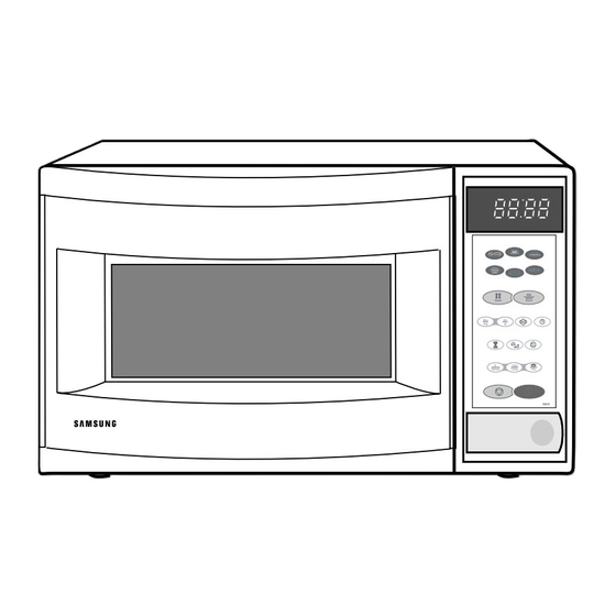
Page 5: Operating Instructions
Power Level Selection Button Memory Button Cooking Timer/ Timer Setting Button Standing Time Button 10min 1min 10s. Stop/Clear Button 1min+ Standard Boost Button M245 3-2 Features & External Views Ventilation Slot Heater Light Door Safety Interlock Holes Auto Auto Control Panel lbs. -
Page 6: Disassembly And Reassembly
VOLTAGE TRANSFORMER secondary and filament terminals. It is extremely dangerous to work on or near these circuits with the oven energized. Screws H. V. Trans DO NOT measure the voltage in the high voltage circuit including filament voltage of magnetron. Samsung Electronics... -
Page 7: Replacement Of Door Assembly
1. Insertion depth of the thin metal plate should be 0.5mm or less. 4-3-4 Removal of Key Door & Spring Remove pin hinge from Door "E" Door "E" Detach spring from Door "E" and key door. Key Door Spring Samsung Electronics... -
Page 8: Replacement Of Fuse/Drive Motor
Base Plate 8. Connect all the leads to the drive motor. Drive Motor Cover 9. Screw the deive motor cover to the base plate with a screw driver. 10. Remount the coupler in the correct position. Samsung Electronics... - Page 9 3. When installing new membrane key board, make sure that the surface of escutcheon base is cleaned sufficiently so that any problems Membrane (shorted contacts or uneven surface) can be Panel avoided. Samsung Electronics...
-
Page 10: Alignment And Adjustments
3. Before touching any oven components or wiring, always unplug the oven from its power source and discharge the high voltage capacitor. 5-1 High Voltage Transformer 1. Remove connectors from the transformer terminals Filament Terminals and check continuity. 2. Normal resistance readings are as follows: MODEL M245 Secondary Approx. 95.6Ω Filament Approx.0.08Ω Primary Approx.1.58Ω Secondary... -
Page 11: High Voltage Capacitor
∞ procedures. Primary switch ∞ Monitor switch (COM-NC) 5. Confirm that the gap between the switch ∞ Monitor switch (COM-NO) housing and the switch actuator is no more than ∞ Door Sensing S/W 0.5mm when door is closed. Samsung Electronics... - Page 12 5. After heating for 2 minutes, measure the water temperature in each beaker. 6. Microwave heat distribution rate can be calculated as follows: Minimum Beaker Temperature Rise Heat Distribution = X 100(%) Maximum Temperature Rise The result should exceed 65%. Cooking Tray Samsung Electronics...
-
Page 13: Procedure For Measurement Of Microwave Energy Leakage
Hold the probe 10min 1min 10s. 1min+ M245 perpendicular to the cabinet door. Place the spacer cone of the probe on the door and/or cabinet door seam and move along the seam, the door viewing window and the exhaust openings moving the probe in a clockwise direction at a rate of 1 inch/sec. -
Page 14: Troubleshooting
H.V.Transformer component test procedure and replace if it is H.V.Capacitor defective. H.V.Diode, H.V.Fuse Magnetron 4. Open or loose wiring of power relay 5. Defective primary latch switch 6. Defective power relay or Ass'y PCB Replace PCB main. Samsung Electronics... - Page 15 Use plastic wrap or cover with a lid. Stir once or twice while cooking foods such as soup, cocoa, or milk. Noise from the turntable motor Noise may result from the motor. Replace turntable motor. when it starts to operate. Samsung Electronics...
-
Page 16: Exploded Views And Parts List
7. Exploded Views and Parts List 7-1 Exploded Views Samsung Electronics... -
Page 17: Main Parts List
PANEL-OUTER;SECC T(0.6) W(424.7) L(1155) DE61-80002A HINGE-UPPER;SCP1 T2.3 26 77 ZPC3 WHT CHR DE61-80003A HINGE-LOWER;SCP1 T2.3 26 77 ZPC3 WHT CHR DE91-40093A ASSY NOISE FILTER;SN-E10D 250V 10A DE31-10157B MOTOR-FAN;SMF 245EA 230V50HZ 2320 M245 DE47-20009A THERMOSTAT;CS-7SA(160/60)187Y 250V7.5A 1 DE03-30035A MAGNETRON;OM75PH((31)ESS 4713-001004 LAMP-INCANDESCENT;230V,-,40W,ORG,-,-,25x DE71-60016A COVER-AIR;PP 2 WHT M945/MB45... -
Page 18: Door Parts List
TAPE-DOUBLE FACE;ACRYL T0.45 W9 WHT WF10 DE64-40009A DOOR-A;ABS(HR0370U) T2.5 IDEOMW6574W 28 DE92-50128F ASSY DOOR-E;COATING BLK MW6575G DE64-40010B DOOR-C;PP(TB53) T1.5 BLK 1.2CU.FT M245 DE01-00004A FILM-DOOR;PE T(0.15) W(183) L(325) NTR 1 DE64-40006A DOOR-KEY;POM(TC3005) T2.0 12GR BLK CE9 DE61-70128A SPRING-KEY;HSW3 PI0.6 D5 BLUING 7-4 Control Parts List Ref. -
Page 19: Standard Parts List
SCREW-A;M4 L12 2S TOOTHED MO/FAN DE60-10082A SCREW-A;M4 L12 2S TOOTHED NO-FIL DE60-10082A SCREW-A;M4 L12 2S TOOTHED OUT-PN DE60-10082A SCREW-A;M4 L12 2S TOOTHED P-CORD DE60-10082C SCREW-TAP TH;TH M4 L8 MSWR3 ZPC YWL WS DE02-00125A TAPE-DOUBLE FACE;ACRYL T0.45 W9 WHT WF10 Samsung Electronics... - Page 20 8. P.C.B Diagrams 8-1 P.C.B Diagram Samsung Electronics...
- Page 21 C-CERAMIC;CC OA CH 50V T 220-J 3.5X1.9 U C07,08 A4106-0154 DIODE-ZENER;TZP5.1B 5.1/5.7V 40MA T 1W ZD01~03 DE07-10081A V.F.DISPLAY;SVM-4SM03 GRN/RSHORG 4 51 81 VFD1 DE09-30508A IC-MCU;HD404316-C15S DIP M945/M245(EURO) IC01 DE13-20009A IC;KA7533 DIP IC02 DE26-20141A TRANS-L.V;SLV-945E 230V 50HZ AC17/2.9V LVT1 DE30-20016A BUZZER;CBE2220BA STICK...
-
Page 22: Schematic Diagrams
SENSING 3. LAMP : ON SYMBOL COLOR RELAY RELAY RELAY SWITCH L.V.T : P.C.B PATTERN BROWN BLUE : P.C.B IN/OUT ORANGE POINT ASSY MAIN P.C.B WHITE BLACK YELLOW DOOR MONITOR PRIMARY GREEN SWITCH LATCH SENSING YELLOW/GREEN SWITCH SWITCH Samsung Electronics...