York 10 SEER Installation Instruction
York 10 seer; 12 seer; 14 seer outdoor split-system heat pump
Hide thumbs
Also See for 10 SEER:
- Owner's manual (4 pages) ,
- Installation instruction (12 pages) ,
- User's information manual (4 pages)
Table of Contents
Advertisement
INSTALLATION
INSTRUCTION
TABLE OF CONTENTS
GENERAL INFORMATION . . . . . . . . . . . . . . . . . . . 2
INSPECTION . . . . . . . . . . . . . . . . . . . . . . . . . . . . . . 2
REFERENCE . . . . . . . . . . . . . . . . . . . . . . . . . . . . . . 2
LIMITATIONS . . . . . . . . . . . . . . . . . . . . . . . . . . . . . . 2
INSTALLATION . . . . . . . . . . . . . . . . . . . . . . . . . . . 4
OUTDOOR UNIT . . . . . . . . . . . . . . . . . . . . . . . . . . . 4
DISCHARGE LINE FILTER-DRIER . . . . . . . . . . . . . 4
OUTDOOR THERMOSTATS . . . . . . . . . . . . . . . . . . 4
INDOOR UNITS . . . . . . . . . . . . . . . . . . . . . . . . . . . . 4
REFRIGERANT LINE (SWEAT FIT) . . . . . . . . . . . . 4
INSULATION OF VAPOR LINE . . . . . . . . . . . . . . . . 5
CLEANING OF JOINT CONNECTIONS . . . . . . . . . 5
REFRIGERANT LINE SUPPORT . . . . . . . . . . . . . . 5
CHARGING AND LEAK TESTING . . . . . . . . . . . . . . 5
TOTAL LINE LENGTH . . . . . . . . . . . . . . . . . . . . . . . 5
(ON SWEAT FIT UNITS) . . . . . . . . . . . . . . . . . . . . . 6
OIL TRAPPING . . . . . . . . . . . . . . . . . . . . . . . . . . . . 6
(QUICK CONNECT UNITS) . . . . . . . . . . . . . . . . . . . 7
SEQUENCE OF OPERATION . . . . . . . . . . . . . . . 12
COOLING . . . . . . . . . . . . . . . . . . . . . . . . . . . . . . . . 12
HEATING . . . . . . . . . . . . . . . . . . . . . . . . . . . . . . . . 12
EMERGENCY HEAT . . . . . . . . . . . . . . . . . . . . . . . 12
10 & 12 SEER WITH TIME/TEMP. DEFROST . . . 12
14 SEER WITH DEMAND DEFROST . . . . . . . . . . 12
INSTALLER . . . . . . . . . . . . . . . . . . . . . . . . . . . . . . 15
COMPENSATOR TANK FUNCTION . . . . . . . . . . . 15
OPTIONAL OUTDOOR THERMOSTAT . . . . . . . . 15
CAUTION: READ ALL SAFETY GUIDES BEFORE YOU
START TO INSTALL YOUR UNIT.
SAVE THIS MANUAL
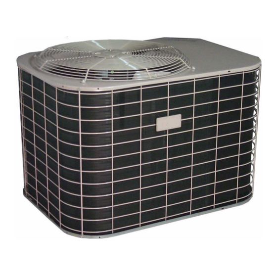
OUTDOOR SPLIT-SYSTEM
HEAT PUMP
MODELS: 10, 12 AND 14 SEER
1.5 TO 5 TONS
035-15713-003 REV. A (0500)
Advertisement
Table of Contents

Related Manuals for York 10 SEER


Summary of Contents for York 10 SEER
-
Page 1: Table Of Contents
INSTALLATION OUTDOOR SPLIT-SYSTEM HEAT PUMP INSTRUCTION MODELS: 10, 12 AND 14 SEER 1.5 TO 5 TONS TABLE OF CONTENTS GENERAL INFORMATION ....2 INSPECTION . -
Page 2: General Information
035-15713-003 REV. A (0500) GENERAL INFORMATION These outdoor heat pump units are designed to be con- nected to a matching UPG indoor coil. They are equipped with a solid core filter-drier located in the discharge line and a The manufacturer is not responsible for the perfor- high pressure switch. - Page 3 035-15713-003 REV. A (0500) Locate the outdoor unit near enough to the indoor coil vicinity Provide ample clearance from shrubs to allow adequate air to to eliminate lengthy refrigerant line runs. Do not locate the pass across the outdoor coil without leaves or branches outdoor unit so it discharges air under eaves or gutters.
-
Page 4: Installation
035-15713-003 REV. A (0500) INSTALLATION OUTDOOR THERMOSTATS An outdoor thermostat may be used with this heat pump sys- OUTDOOR UNIT (All installations of this heat pump in Manufac- tem. After the site has been selected, a solid base pad that will not tured Homes built per HUD standards SHALL have shift or settle should be provided. -
Page 5: Insulation Of Vapor Line
035-15713-003 REV. A (0500) INSULATION OF VAPOR LINE Reassemble groups of tubing and fittings, brazing several joints instead of one joint at a time. This reduces the chance Insulate vapor line with 3/8" (or that required by local code) for error in the alignment of the assembly. Replace Schrader closed cell insulation. -
Page 6: Orifice Selection (On Sweat Fit Coils)
035-15713-003 REV. A (0500) ORIFICE SELECTION (ON SWEAT FIT COILS) Replace valve cap finger tight, then tighten an additional 1/6 of a turn with a wrench, using a back-up wrench on the valve NOTE: The proper orifice must be installed in the indoor coil body. -
Page 7: Refrigerant Lines (Quick Connect Units)
035-15713-003 REV. A (0500) REFRIGERANT LINES (QUICK CONNECT UNITS) Forming Copper. No attempt should be made to bend the suction line IMPORTANT - Do not remove protective caps from cou- in a shorter radius than 12". See Figure 5. plings until pre-charged lines are routed and ready for final connection. - Page 8 035-15713-003 REV. A (0500) Install refrigerant lines to indoor coil first. (The couplings without Schrader Valves are to be connected to the indoor coil. See Figure 9). Form the tubing so it is properly aligned with the connections on the coil. Remove plugs and caps from connections.
- Page 9 035-15713-003 REV. A (0500) Tightening couplings. ELECTRICAL WIRING Tighten indoor coil couplings with wrenches; using wrench on stationary fitting of coupling and liquid line fitting at coil while nut is being tightened. See Figure 9. Tighten the nut until the coupling bottoms To prevent electrical shock, open remote disconnect out.
- Page 10 Figures 15 or 16 and per the instructions packed with those pieces. FIGURE 11 : OUTDOOR UNIT CONTROL BOX (12 SEER 048, 060) FIGURE 10 : OUTDOOR UNIT CONTROL BOX (10 SEER 018-060 & 12 SEER 018-042) FIGURE 12 : OUTDOOR UNIT CONTROL BOX (14 SEER) Unitary Products Group...
- Page 11 035-15713-003 REV. A (0500) FIGURE 13 : DEMAND DEFROST BOARD (14 SEER) FIGURE 14 : TIME/TEMPERATURE DEFROST BOARD (10 & 12 SEER) Unitary Products Group...
- Page 12 035-15713-003 REV. A (0500) FIGURE 15 : TYPICAL RESIDENTIAL AIR HANDLER FIGURE 16 : TYPICAL MANUFACTURED HOUSING INSTALLATION Unitary Products Group...
-
Page 13: Sequence Of Operation
035-15713-003 REV. A (0500) SEQUENCE OF OPERATION TIME/TEMPERATURE DEFROST: The defrost control is a time/temp. control which includes a COOLING field-selectable (white tap located at board edge) time period between defrost cycle (30, 60, and 90 minutes). Factory set On call for cooling, the thermostat makes 24V circuits: R to at 60 minutes. - Page 14 035-15713-003 REV. A (0500) DEMAND DEFROST: TEST PINS ON DEMAND DEFROST: The defrost control is a demand defrost control. See Figure The test pins labeled "speed-up" and "defrost" are provided 13. Due to the arrangement of the refrigerant circuit within the to aid in field servicing of the heat pump.
- Page 15 035-15713-003 REV. A (0500) FIGURE 18 : FLOW DIAGRAM - 060 (10 SEER) FIGURE 19 : FLOW DIAGRAM - 024 THRU 048 (14 SEER) Unitary Products Group...
-
Page 16: Installer
Part number 3024-6881/D shall be used and should be ordered at your nearest UPG Parts Source. Subject to change without notice. Printed in U.S.A. 035-15713-003 REV. A (0500) Copyright © by York International Corp. 2000. All rights reserved. Supersedes:035-15713-402 REV. C (0400) Unitary 5005 Norman...