Table of Contents
Advertisement
Advertisement
Table of Contents
Troubleshooting

Related Manuals for Immergas VICTRIX X 12-24 2I


Summary of Contents for Immergas VICTRIX X 12-24 2I
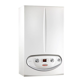
- Page 1 VICTRIX Instruction and Warning book X 12-24 2 I *1.031274IE*...
-
Page 3: Table Of Contents
Read the following pages carefully: you will be able to draw useful suggestions regarding the correct use of the appliance, the respect of which, will con rm your satisfaction for the Immergas product. -
Page 4: Boiler Installation
Packing recessed frame for the Victrix X 12-24 2I boiler is materials (staples, nails, plastic bags, polystyrene not a supporting structure and must not replace foam, etc.) constitute a hazard and must be kept... -
Page 5: Main Dimensions
RU - Storage tank unit return (optional) e materials used for the central heating circuit CONNECTIONS MU - Storage tank unit ow (optional) of Immergas boilers resist ethylene and propylene DOMESTIC SYSTEM RR - System lling glycol based antifreeze liquids (if the mixtures are SC - Condensate drain (minimum prepared perfectly). - Page 6 1.5 ATTACHMENTS. Hydraulic connection Electrical connection: e "Victrix X 12-24 2I" Gas connection (Appliance category II boiler has an IPX4D protection rating for the Important: In order not to void the warranty 2H3B/P entire appliance. Electrical safety of the appliance...
-
Page 7: Remote Controls And Room Chrono
(comfort temperature) and one for night type of room chrono-thermostat used and can be connected to clamps 40 and 41 eliminating (lower temperature); work in combination with Immergas chrono- jumper X40 (Fig. 3-2). Make sure that the On/ thermostats. e correlation between system - to set up to four on/o di erential weekly O thermostat contact is of the “clean”... -
Page 8: Immergas Ue Systems
Important: the boiler must be installed • Con guration type B, open chamber and evaluated with respect to the balcony above, exclusively with an original Immergas “Green forced draught. must be equal to or more than 2000 mm. (Fig. Range” air intake and flue gas extraction Using the relevant cover kit direct air intake is 1-15). - Page 9 1-13 1-14 e cover kit includes: N° 1 Heat moulded cover N°1 Gasket clamping plate N°1 Gasket N°1 Gasket clamp N°1 N°1 Intake hole covering plate e terminal kit includes: N° 1 Gasket N° 1 Exhaust ange Ø 80 N° 1 Bend 90°...
- Page 10 Tables of Resistance Factors and Equivalent Lengths. Equivalent Equivalent Equivalent Resistance length in m of concentric length in metres length in metres DUCT TYPE Factor pipe Ø 60/100 of pipe Ø 80 of pipe Ø 60 Concentric pipe Ø 60/100 m 1 Intake m 7.3 Intake and Exhaust m 1.9...
-
Page 11: Indoor Installation
1.11 INDOOR INSTALLATION. Note: when the boiler is installed in areas where e kit Ø 60/100 can be installed with the rear, • Type C con guration, sealed chamber and right side, le side or front outlet. very rigid temperatures can be reached, a special fan assisted. -
Page 12: Ducting Of Ue Technical Slots
Separator kit Ø 80/80. e Ø 80/80 separator • Coupling of extension pipes and elbows. To - Type B open chamber boilers must not be kit, allows separation of the exhaust ues and install push-fitting extensions with other installed in places where commercial, artisan air intake pipes according to the diagram shown elements of the flue extraction elements or industrial activities take place, which use... -
Page 13: Flue Exhaust To Ue/Chimney
Ø80 exible “Green Range” ducting systems must Flue exhaust does not necessarily have to be To start up the system, make reference to the only be used for domestic use and with Immergas connected to a branched type traditional ue. Standard: is divides the systems and therefore condensing boilers. -
Page 14: Circulation Pump
1.19 CIRCULATION PUMP. By-pass regulation (part. 25 Fig. 1-28). If The “Victrix X 12-24 2I” series boilers are necessary, the by-pass can be regulated according supplied with a built-in circulation pump with to system requirements from a minimum (by- 3-position electric speed control. The boiler... -
Page 15: Kits Available On Request
(max. three) in order to interlock them with separate adjustments and to keep water ow rate high for each zone, Immergas supplies zone system kits on request. • External storage tank unit coupling kit (on request). -
Page 16: Boiler Components
1.21 BOILER COMPONENTS. Key: 15 - Negative signal pressure point 1 - Electric connection terminal board 16 - Positive signal pressure point (very low voltage) 17 - Igniter 2 - Condensate drain trap 18 - Ignition electrode 3 - Gas valve 19 - Venturi 4 - Air vent valve 20 - Fan... -
Page 17: Cleaning And Maintenance
Important: indicates a pressure of 1 ÷ 1.2 bar. via the indicator (14). the Victrix X 12-24 2I boiler has been designed - Open the gas cock upstream from the boiler. to operate as an appliance for room central • Winter (... -
Page 18: Troubleshooting
Flue safety thermostat block is function must be pressed. Call an authorised technician is activated automatically if the boiler detects to remove the obstructions (e.g. Immergas A er- a probe on the DHW inlet (optional) or if the Contacts resistance block sales Service). - Page 19 (e.g. Immergas A er-Sales Technical Assistance the room central heating requests. A quali ed Signalling and diagnostics - Display of the Service). technician must be called (e.g. Immergas A er- Remote Control (Optional). During Sales Service). Push button control panel anomaly.
-
Page 20: Boiler Shutdown
1 and 1.2 bar. of the Immergas Anti-freeze Kit in the boiler. In If the pressure falls below 1 bar (with the circuit the case of prolonged inactivity (second case),... -
Page 21: Boiler Start-Up (Initial Check)
BOILER - check the ∆p gas values in domestic hot water - ensure sealing e ciency of water circuits; and heating modes; COMMISSIONING INITIAL - check ventilation and/or aeration of the - check the CO in the combustion products at installation room where provided. -
Page 22: Wiring Diagram
Check, the Comando Amico Remoto remote control out by a qualified technician (e.g. Immergas by means of the condensate drain cap, that (CAR , which must be connected to clamps 41 A er-Sales Technical Assistance Service). -
Page 23: Converting The Boiler To Other Types Of Gas
Boiler conversion must be carried out by a the voltage from the boiler. output output quali ed technician (e.g. Immergas Technical (central heating) (central heating) Calibration of the minimum CO (minimum Assistance Service). G 20 9.50% ±... -
Page 24: Programming The P.c.b
3.8 PROGRAMMING THE P.C.B. e boiler is prepared for possible programming of several operation parameters. By modifying these parameters as described below, the boiler can be adapted according to speci c needs. To access the programming phase, position the DHW selector (5) on position “6”, the CH selector (6) on position “9”... - Page 25 Parameter Parameter Description Range Default Establishes the boiler ignition and switch-o mode in DHW mode. On = -7°C 0 - Ignition occurs when the water contained in the storage tank drops by 7°C with respect O = -4°C to the temperature set and switches o when the temperature is at -4°C with respect to the value set (solar deactivated) 1 - Ignition occurs when the water contained in the storage tank drops by 2°C with respect DHW thermostat...
-
Page 26: Solar Panels Coupling Function
3.9 SOLAR PANELS COUPLING 3.15 AUTOMATIC VENT FUNCTION. 3.17 YEARLY APPLIANCE CHECK AND FUNCTION. MAINTENANCE. In the case of new heating systems and in The boiler is set-up to receive water. In the particular mode for floor systems, it is very e following checks and maintenance should event of integration of heating of the DHW with important that dearation is performed correctly. -
Page 27: Casing Removal
3.18 CASING REMOVAL. To facilitate boiler maintenance the casing can be completely removed as follows: - disassemble the lower plastic protection grid (1) by loosening the two lower screws (2); - loosen the two screws (4) present in the lower part of the casing front (3);... -
Page 28: Variable Heat Output
3.19 VARIABLE HEAT POWER. sealed chamber (see pressure test 15 and 16 Fig. measuring 0.5 m in length. Gas ow rates refer N.B.: the pressures indicated in the table 1-28). e adjustments must be performed using to heating values below a temperature of 15°C represent the differences of pressures at the a digital di erential manometer with a scale in and at a pressure of 1013 mbar. -
Page 29: Combustion Parameters
3.20 COMBUSTION PARAMETERS. Supply pressure mbar (mm H 20 (204) 29 (296) 37 (377) Victrix X 12 2 I Gas nozzle diameter 3.70 2.80 2.80 Flue ow rate at nominal heat output kg/h Flue ow rate at min heat output kg/h at Nom Q./Min. -
Page 30: Technical Data
Total head available with 1000 l/h ow rate kPa (mm H 6,7 (0,68) 25,8 (2,64) *Speci c capacity “D” UB Immergas 80 l (∆T 30°C) according to EN 625 l/min 17,2 20,5 *Speci c capacity “D” UB Immergas 105 l (∆T 30°C) according to EN 625... - Page 32 Immergas S.p.A. 42041 Brescello (RE) - Italy T. +39.0522.689011 F. +39.0522.680617 immergas.com...