
Related Manuals for York R-407C Optimized


Summary of Contents for York R-407C Optimized
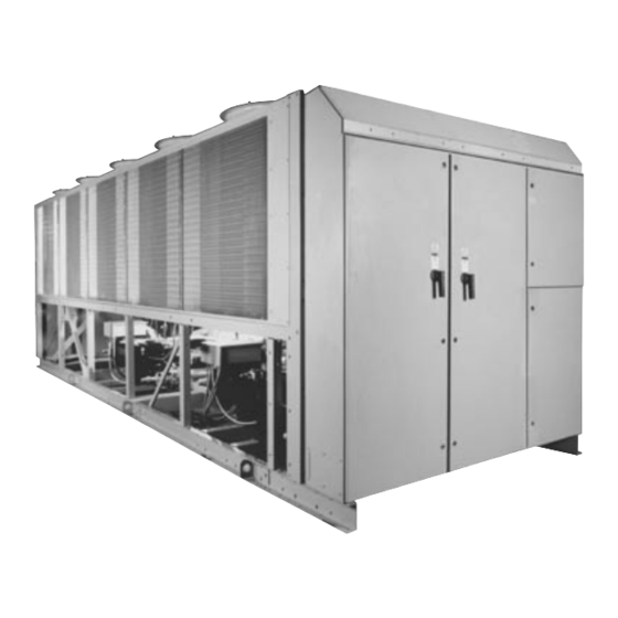
- Page 1 FORM 201.19-EG4 (903) Better ecology, Better economy. Air Cooled Screw Liquid Chillers (STYLE G) 28971AR 200, 230,380, 460, AND 575 50 – 200 Tons R-407C Optimized 80 – 400 Tons 280 kW – 1400 kW 60 Hz...
-
Page 2: Table Of Contents
Power Connection Options................106 Typical Control Wiring..................110 Application Data ....................112 Guide Specifications............................................. NOMENCLATURE 0208 YORK Chiller Design Series YC = YORK Chiller Type Start Y = Star (WYE)-Delta Air-Cooled X = Across-the-Line Compressor Type S = Screw Voltage Code 17 = 200-3-60... -
Page 3: Introduction
FORM 201.19-EG4 Introduction YORK Air Cooled Screw Liquid Chillers R-407C Optimized 28971AR The YORK eco technology takes the YCAS Air Cooled Screw Chillers yet another step beyond the competition. Using unique (patent pending) heat transfer design, the eco chillers exploit the special “glide” characteristic of HFC refrigerant R-407C, resulting in excellent performance from a machine using a zero ozone depletion refrigerant. -
Page 4: Specifications
Specifications These YORK air cooled chillers are shipped as a heat exchangers. While flooded designs are easily complete factory package. Each unit is completely as- employed on indoor equipment, DX is preferred on sembled with all interconnecting refrigerant piping and... - Page 5 REFRIGERANT CIRCUIT: maximum efficiency. • Each refrigerant circuit of YORK’s eco design utilizes • Condenser fan motors are high efficiency, direct drive, a Suction Line Heat Exchanger (SLHX), a refrigerant 6-pole, 3-phase, Class-“F,”...
- Page 6 Day, date and time. Daily start/stop times. Holiday (dry contact) reset input. [NOTE: The Standard and Manual Override status. MicroPanel can be directly connected to a YORK w Compressor operating hours and starts. Auto- ISN Building Automation System via the standard matic or manual lead/lag.
- Page 7 Two motor control per condenser fan motor. center cabinets are provided, with independent doors • Exposed compressor and fan motor power wiring and separated by a steel panel. routed through liquid tight conduit. YORK INTERNATIONAL...
-
Page 8: Accessories And Options
(in compliance with Article 440-14 of N.E.C., to iso- ers and wet bromine, chlorine and fluorine in concentra- late unit power supply for service). Factory wiring tions greater than 100 ppm). is provided from the Terminal Block or Disconnect Switch to factory supplied Individual System Circuit YORK INTERNATIONAL... - Page 9 – Louvered panels mounted over the exterior (Field-mounted) condenser coil faces, and heavy gauge welded • ALTERNATIVE CHILLED FLUID APPLICATIONS: wire mesh guards mounted around the bottom of Standard water chilling application range is 40°F the unit. Visually screens and protects coils, and YORK INTERNATIONAL...
- Page 10 See Form 201.18-ES1 for additional BAS. information. w A YORK ISN Building Automation System can ♦ Low Speed Fans – With this option, the basic provide a Pulse Width Modulated (PWM) signal chiller is equipped with 8-pole condenser fan mo-...
-
Page 11: Temperatures And Flows
1. For leaving brine temperature below 40°F, contact your nearest YORK office for application requirements. 2. For leaving water temperature higher than 5.5°F, contact the nearest YORK office for application guidelines. 3. The evaporator is protected against freeze-up to -20°F with an electrical heater as standard. -
Page 12: Water Pressure Drop
Water Pressure Drop (English Units) ENGLISH UNITS LD05825 MODEL NUMBER YCAS COOLER 0098, 0118, 0138 0128, 0148, 0158, 0178, 0198, 0208 YORK INTERNATIONAL... - Page 13 FORM 201.19-EG4 ENGLISH UNITS LD06102 MODEL NUMBER YCAS COOLER 0218, 0248, 0268 0288, 0308, 0328 0358, 0398, 0418 YORK INTERNATIONAL...
- Page 14 Water Pressure Drop (SI Units) SI UNITS WATER PRESSURE DROP – 2 COMPRESSOR UNITS 1000 Water Flow (I/s) LD05884 MODEL NUMBER YCAS COOLER 0098, 0118, 0138 0128, 0148, 0158, 0178, 0198, 0208 YORK INTERNATIONAL...
- Page 15 FORM 201.19-EG4 SI UNITS WATER PRESSURE DROP – 3 & 4 COMPRESSOR UNITS C4 C5 1000 10000 Water Flow (I/s) LD06103 MODEL NUMBER YCAS COOLER 0218, 0248, 0268 0288, 0308, 0328 0358, 0398, 0418 YORK INTERNATIONAL...
-
Page 16: Ratings
Ratings – R-407C Optimized (English Units) AIR TEMPERATURE ON CONDENSER (°F) LCWT (°F) TONS TONS TONS TONS TONS MODEL YCAS0098EB (IPLV = 13.2) 40.0 93.2 72.6 13.4 90.5 77.4 12.3 87.5 82.7 11.2 84.4 88.4 10.2 81.3 94.5 42.0 96.1 72.5... - Page 17 3. LCWT = Leaving Chilled Water Temperature 4. Ratings based on 2.4 GPM cooler water per ton 5. Rated in accordance with ARI Standard 550/590-98 6. Shaded Ratings certified in accordance with ARI Standard 550/590-98 up to 200 tons. YORK INTERNATIONAL...
- Page 18 Ratings – R-407C Optimized (English Units, continued) AIR TEMPERATURE ON CONDENSER (°F) LCWT (°F) TONS TONS TONS TONS TONS MODEL YCAS0138EB (IPLV = 13.6) 40.0 134.0 103.7 13.6 129.6 110.9 12.4 125.2 118.6 11.3 120.8 126.9 10.3 116.5 135.8 42.0 138.5...
- Page 19 3. LCWT = Leaving Chilled Water Temperature 4. Ratings based on 2.4 GPM cooler water per ton 5. Rated in accordance with ARI Standard 550/590-98 6. Shaded Ratings certified in accordance with ARI Standard 550/590-98 up to 200 tons. YORK INTERNATIONAL...
- Page 20 Ratings – R-407C Optimized (English Units, continued) AIR TEMPERATURE ON CONDENSER (°F) LCWT (°F) TONS TONS TONS TONS TONS MODEL YCAS0178EB (IPLV = 13.3) 40.0 177.5 145.0 13.4 171.4 154.6 12.2 165.3 165.2 11.0 159.3 176.6 10.0 153.4 188.7 42.0 183.3...
- Page 21 3. LCWT = Leaving Chilled Water Temperature 4. Ratings based on 2.4 GPM cooler water per ton 5. Rated in accordance with ARI Standard 550/590-98 6. Shaded Ratings certified in accordance with ARI Standard 550/590-98 up to 200 tons. YORK INTERNATIONAL...
- Page 22 Ratings – R-407C Optimized (English Units, continued) AIR TEMPERATURE ON CONDENSER (°F) LCWT (°F) TONS TONS TONS TONS TONS MODEL YCAS0218EB (IPLV = 13.5) 40.0 224.8 154.5 14.3 217.1 165.1 13.1 209.3 176.6 11.9 201.6 188.9 10.9 194.1 202.1 42.0 232.1...
- Page 23 = Chiller EER (includes power from compressors, fans, and control panels 0.8 kW) 3. LCWT = Leaving Chilled Water Temperature 4. Ratings based on 2.4 GPM cooler water per ton 5. Rated in accordance with ARI Standard 550/590-98 YORK INTERNATIONAL...
- Page 24 Ratings – R-407C Optimized (English Units, continued) AIR TEMPERATURE ON CONDENSER (°F) LCWT (°F) TONS TONS TONS TONS TONS MODEL YCAS0288EB (IPLV = 12.7) 40.0 294.5 233.8 13.2 284.2 249.3 12.1 274.0 266.2 11.0 264.1 284.3 10.0 254.3 303.7 42.0 304.0...
- Page 25 = Chiller EER (includes power from compressors, fans, and control panels 0.8 kW) 3. LCWT = Leaving Chilled Water Temperature 4. Ratings based on 2.4 GPM cooler water per ton 5. Rated in accordance with ARI Standard 550/590-98 YORK INTERNATIONAL...
- Page 26 Ratings – R-407C Optimized (English Units, continued) AIR TEMPERATURE ON CONDENSER (°F) LCWT (°F) TONS TONS TONS TONS TONS MODEL YCAS0358EB (IPLV = 13.6) 40.0 376.2 285.8 13.7 363.2 304.6 12.5 350.1 325.4 11.3 337.4 347.7 10.3 324.9 371.4 42.0 388.5...
- Page 27 = Chiller EER (includes power from compressors, fans, and control panels 0.8 kW) 3. LCWT = Leaving Chilled Water Temperature 4. Ratings based on 2.4 GPM cooler water per ton 5. Rated in accordance with ARI Standard 550/590-98 YORK INTERNATIONAL...
- Page 28 Ratings – R-407C Optimized (SI Units) AIR TEMPERATURE – CONDENSER (°C) LCWT (°C) kWi COP kWo kWi COP kWo kWi COP kWo COP kWo kWi COP kWo MODEL YCAS0098EB 329.5 74.4 310.8 83.7 291.2 94.4 272.3 106.5 254.4 120.0 233.0 131.8...
- Page 29 1. kWo = Unit kW Cooling Capacity Output 2. kWi = Compressor kW Input 3. COP = Coefficient of Performance (includes condenser fan power) 4. LCWT = Leaving Chilled Water Temperature 5. Ratings based on 0.15 l/s cooler water per ton. YORK INTERNATIONAL...
- Page 30 Ratings – R-407C Optimized (SI Units, continued) AIR TEMPERATURE – CONDENSER (°C) LCWT (°C) kWi COP kWo kWi COP kWo kWi COP kWo COP kWo kWi COP kWo MODEL YCAS0178EB 625.9 149.1 586.8 167.9 548.8 189.3 513.7 212.8 481.4 239.1 347.0...
- Page 31 FORM 201.19-EG4 Ratings – R-407C Optimized (SI Units, continued) AIR TEMPERATURE – CONDENSER (°C) LCWT (°C) kWi COP kWo kWi COP kWo kWi COP kWo COP kWo kWi COP kWo MODEL YCAS0218EB 793.1 159.0 4.1 743.1 179.3 3.5 695.3 202.2 649.5...
- Page 32 Ratings – R-407C Optimized (SI Units, continued) AIR TEMPERATURE – CONDENSER (°C) LCWT (°C) kWi COP kWo kWi COP kWo kWi COP kWo COP kWo kWi COP kWo MODEL YCAS0288EB 1037.4 240.8 3.8 972.5 270.6 3.2 909.8 304.5 850.9 342.5 794.2...
- Page 33 1. kWo = Unit kW Cooling Capacity Output 2. kWi = Compressor kW Input 3. COP = Coefficient of Performance (includes condenser fan power) 4. LCWT = Leaving Chilled Water Temperature 5. Ratings based on 0.15 l/s cooler water per ton. YORK INTERNATIONAL...
-
Page 34: Physical Data
Physical Data – R-407C Optimized (English) MODEL NUMBER YCAS Refrigerant R-407C Optimized 0098EB 0118EB 0128EB 0138EB 0148EB 0158EB 0178EB 0198EB 0208EB General Unit Data Unit Capacity at 44°F water & 95°F ambient, TR 87.3 106.7 112.1 126.8 130.5 145.5 164.2 178.1... - Page 35 35.4 35.4 35.4 35.4 35.4 10,575 10,575 10,575 10,575 10,575 10,575 10,575 10,575 10,575 186,000 186,000 186,000 186,000 217,000 248,000 248,000 279,000 279,000 1072 1072 1072 1205 1205 1205 1601 1601 1601 NOTE: Optional 300 PSIG waterside available YORK INTERNATIONAL...
- Page 36 Physical Data – R-407C Optimized (SI) MODEL NUMBER YCAS Refrigerant R-407C Optimized 0098EB 0118EB 0128EB 0138EB 0148EB 0158EB 0178EB 0198EB 0208EB General Unit Data Unit Capacity at 7°C water & 35°C ambient, kW Number of Independent Refrigerant Circuits Refrigerant Charge, R-407C, Ckt.-1/Ckt.-2, kg.
- Page 37 5/3.3 5/3.3 5/3.3 5/3.3 5/3.3 5/3.3 5/3.3 5/3.3 53.7 53.7 53.7 53.7 53.7 53.7 53.7 53.7 53.7 87,783 87,783 87,783 87,783 102,413 117,043 117,043 131,674 131,674 1013 1013 1013 67.64 67.64 67.64 NOTE: Optional 21 Bar waterside available YORK INTERNATIONAL...
-
Page 38: Dimensions
Site restrictions may compromise minimum clearances indicated below, resulting in unpredictable air flow patterns and possible diminished performance. YORK's unit controls will optimize operation without nuisance high pressure safety cutout; however, the system designer must consider potential performance degradation. Access to the unit control center assumes the unit is no higher than on spring isolators. - Page 39 FORM 201.19-EG4 ��� ��� LD05184 CENTER OF GRAVITY (Alum.) CENTER OF GRAVITY (Copper) YCAS YCAS 0098 77.5 44.9 38.8 0098 77.4 44.8 41.0 0118 76.9 45.0 38.3 0118 77.3 45.0 38.3 ���� ������� ����� LD05163 YORK INTERNATIONAL...
- Page 40 Site restrictions may compromise minimum clearances indicated below, resulting in unpredictable air flow patterns and possible diminished performance. YORK's unit controls will optimize operation without nuisance high pressure safety cutout; however, the system designer must consider potential performance degradation. Access to the unit control center assumes the unit is no higher than on spring isolators.
- Page 41 7 / 8 " 7 / 8 " OR I GI N V I E W D - D LD05639 CENTER OF GRAVITY (Alum.) CENTER OF GRAVITY (Copper) YCAS YCAS 0128 105.9 42.6 37.1 0128 107.4 42.8 38.6 ��� ��� LD05640 YORK INTERNATIONAL...
- Page 42 Site restrictions may compromise minimum clearances indicated below, resulting in unpredictable air flow patterns and possible diminished performance. YORK's unit controls will optimize operation without nuisance high pressure safety cutout; however, the system designer must consider potential performance degradation. Access to the unit control center assumes the unit is no higher than on spring isolators.
- Page 43 FORM 201.19-EG4 ��� ��� LD05643 CENTER OF GRAVITY (Alum.) CENTER OF GRAVITY (Copper) YCAS YCAS 0138 104.1 45.2 38.8 0138 105.9 45.1 40.2 ��� ��� LD05644 YORK INTERNATIONAL...
- Page 44 Site restrictions may compromise minimum clearances indicated below, resulting in unpredictable air flow patterns and possible diminished performance. YORK's unit controls will optimize operation without nuisance high pressure safety cutout; however, the system designer must consider potential performance degradation. Access to the unit control center assumes the unit is no higher than on spring isolators.
- Page 45 LD05647 CENTER OF GRAVITY (Alum.) CENTER OF GRAVITY (Copper) YCAS YCAS 0148 106.6 42.8 36.6 0148 108.0 42.9 38.1 0158 106.3 42.8 36.5 0158 107.8 42.9 38.0 0178 106.5 42.9 36.5 0178 108.0 43.0 38.0 ��� ��� LD05648 YORK INTERNATIONAL...
- Page 46 Site restrictions may compromise minimum clearances indicated below, resulting in unpredictable air flow patterns and possible diminished performance. YORK's unit controls will optimize operation without nuisance high pressure safety cutout; however, the system designer must consider potential performance degradation. Access to the unit control center assumes the unit is no higher than on spring isolators.
- Page 47 FORM 201.19-EG4 ��� ��� LD05663 CENTER OF GRAVITY (Alum.) CENTER OF GRAVITY (Copper) YCAS YCAS 0198 132.9 43.2 38.4 0198 134.2 43.3 39.8 0208 133.1 43.3 38.1 0208 134.3 43.4 39.5 ��� ��� LD05664 YORK INTERNATIONAL...
- Page 48 Site restrictions may compromise minimum clearances indicated below, resulting in unpredictable air flow patterns and possible diminished performance. YORK's unit controls will optimize operation without nuisance high pressure safety cutout; however, the system designer must consider potential performance degradation. Access to the unit control center assumes the unit is no higher than on spring isolators.
- Page 49 38.7 36" 96" 78" 2" SYS. 1&2 (4) 2 1/4" DIA. RIGGING 10" 7 1/2" 10" HOLES (EACH SIDE) POWER OPENING WATER OUTLET WATER INLET 149 5/8" 128" 68" 89 11/16" 67 7/16" 63 9/16" 342 1/4" LD06106 YORK INTERNATIONAL...
- Page 50 Site restrictions may compromise minimum clearances indicated below, resulting in unpredictable air flow patterns and possible diminished performance. YORK's unit controls will optimize operation without nuisance high pressure safety cutout; however, the system designer must consider potential performance degradation. Access to the unit control center assumes the unit is no higher than on spring isolators.
- Page 51 37.2 36" 96" 78" 2" SYS. 1&2 (4) 2 1/4" DIA. RIGGING 7 1/2" 10" 10" HOLES (EACH SIDE) WATER INLET POWER OPENING WATER OUTLET 157 3/16" 142" 68" 89 11/16" 67 7/16" 63 9/16" 342 1/4" LD06118 YORK INTERNATIONAL...
- Page 52 Site restrictions may compromise minimum clearances indicated below, resulting in unpredictable air flow patterns and possible diminished performance. YORK's unit controls will optimize operation without nuisance high pressure safety cutout; however, the system designer must consider potential performance degradation. Access to the unit control center assumes the unit is no higher than on spring isolators.
- Page 53 96" 78" 2" SYS. 1&2 (4) 2 1/4" DIA. RIGGING 10" 10" 7 1/2" HOLES (EACH SIDE) WATER OUTLET WATER INLET POWER OPENING 157 3/16" 142" POWER OPENING 89 11/16" 115 7/16" 63 9/16" 68" 390 1/4" LD06122 YORK INTERNATIONAL...
- Page 54 Site restrictions may compromise minimum clearances indicated below, resulting in unpredictable air flow patterns and possible diminished performance. YORK's unit controls will optimize operation without nuisance high pressure safety cutout; however, the system designer must consider potential performance degradation. Access to the unit control center assumes the unit is no higher than on spring isolators.
- Page 55 41.0 36" 96" 78" 2" SYS. 1&2 (4) 2 1/4" DIA. RIGGING 10" 10" 7 1/2" HOLES (EACH SIDE) WATER OUTLET WATER INLET POWER OPENING 157 3/16" 142" 68" 89 11/16" 115 7/16" 111 9/16" 438 1/4" LD06126 YORK INTERNATIONAL...
- Page 56 Site restrictions may compromise minimum clearances indicated below, resulting in unpredictable air flow patterns and possible diminished performance. YORK's unit controls will optimize operation without nuisance high pressure safety cutout; however, the system designer must consider potential performance degradation. Access to the unit control center assumes the unit is no higher than on spring isolators.
- Page 57 78" 2" SYS. 1&2 SYS. 3&4 (4) 2 1/4" DIA. RIGGING 10" 10" 7 1/2" HOLES (EACH SIDE) WATER OUTLET WATER INLET POWER OPENING 264 9/16" 142" 75 1/2" 89 11/16" 105 7/16" 102 1/16" 438 1/4" LD06130 YORK INTERNATIONAL...
- Page 58 Site restrictions may compromise minimum clearances indicated below, resulting in unpredictable air flow patterns and possible diminished performance. YORK's unit controls will optimize operation without nuisance high pressure safety cutout; however, the system designer must consider potential performance degradation. Access to the unit control center assumes the unit is no higher than on spring isolators.
- Page 59 96" 78" 2" SYS. 1&2 SYS. 3&4 (4) 2 1/4" DIA. RIGGING 10" 10" WATER INLET 7 1/2" HOLES (EACH SIDE) WATER OUTLET POWER OPENING 312 9/16" 142" 68" 89 11/16" 169 7/16" 106 9/16" 486 1/4" LD06134 YORK INTERNATIONAL...
- Page 60 Site restrictions may compromise minimum clearances indicated below, resulting in unpredictable air flow patterns and possible diminished performance. YORK’s unit controls will optimize operation without nuisance high pressure safety cutout; however, the system designer must consider potential performance degradation. Access to the unit control center assumes the unit is no higher than on spring isolators.
- Page 61 FORM 201.19-EG4 � � � � � � LD05828 CENTER OF GRAVITY (Alum.) CENTER OF GRAVITY (Copper) YCAS YCAS 0098 1967 1141 0098 1965 1139 1040 0118 1953 1142 0118 1962 1140 1027 ��� ��� LD05829 YORK INTERNATIONAL...
- Page 62 Site restrictions may compromise minimum clearances indicated below, resulting in unpredictable air flow patterns and possible diminished performance. YORK’s unit controls will optimize operation without nuisance high pressure safety cutout; however, the system designer must consider potential performance degradation. Access to the unit control center assumes the unit is no higher than on spring isolators.
- Page 63 FORM 201.19-EG4 ��� ��� LD05832 CENTER OF GRAVITY (Alum.) CENTER OF GRAVITY (Copper) YCAS YCAS 0128 2690 1083 0128 2728 1086 ��� ��� LD05833 YORK INTERNATIONAL...
- Page 64 Site restrictions may compromise minimum clearances indicated below, resulting in unpredictable air flow patterns and possible diminished performance. YORK’s unit controls will optimize operation without nuisance high pressure safety cutout; however, the system designer must consider potential performance degradation. Access to the unit control center assumes the unit is no higher than on spring isolators.
- Page 65 FORM 201.19-EG4 ��� ��� LD05836 CENTER OF GRAVITY (Alum.) CENTER OF GRAVITY (Copper) YCAS YCAS 0138 2645 1148 0138 2689 1146 1021 ��� ��� LD05837 YORK INTERNATIONAL...
- Page 66 Site restrictions may compromise minimum clearances indicated below, resulting in unpredictable air flow patterns and possible diminished performance. YORK’s unit controls will optimize operation without nuisance high pressure safety cutout; however, the system designer must consider potential performance degradation. Access to the unit control center assumes the unit is no higher than on spring isolators.
- Page 67 FORM 201.19-EG4 ��� ��� LD05840 CENTER OF GRAVITY (Alum.) CENTER OF GRAVITY (Copper) YCAS YCAS 0148 2706 1087 0148 2742 1090 0158 2701 1087 0158 2737 1090 0178 2706 1090 0178 2742 1093 ��� LD05841 YORK INTERNATIONAL...
- Page 68 Site restrictions may compromise minimum clearances indicated below, resulting in unpredictable air flow patterns and possible diminished performance. YORK’s unit controls will optimize operation without nuisance high pressure safety cutout; however, the system designer must consider potential performance degradation. Access to the unit control center assumes the unit is no higher than on spring isolators.
- Page 69 FORM 201.19-EG4 ��� ��� LD05844 CENTER OF GRAVITY (Alum.) CENTER OF GRAVITY (Copper) YCAS YCAS 0198 3376 1098 0198 3408 1100 1012 0208 3380 1100 0208 3411 1102 1004 LD05845 YORK INTERNATIONAL...
- Page 70 Site restrictions may compromise minimum clearances indicated below, resulting in unpredictable air flow patterns and possible diminished performance. YORK’s unit controls will optimize operation without nuisance high pressure safety cutout; however, the system designer must consider potential performance degradation. Access to the unit control center assumes the unit is no higher than on spring isolators.
- Page 71 4142 1017 0248 4174 1025 0268 4129 1016 0268 4161 1024 2438 1981 SYS. 1&2 POWER OPENING (4) 57 DIA. RIGGING 10" 10" HOLES (EACH SIDE) WATER OUTLET WATER INLET 3800 3251 1727 2277 1713 1614 8694 LD06112 YORK INTERNATIONAL...
- Page 72 Site restrictions may compromise minimum clearances indicated below, resulting in unpredictable air flow patterns and possible diminished performance. YORK’s unit controls will optimize operation without nuisance high pressure safety cutout; however, the system designer must consider potential performance degradation. Access to the unit control center assumes the unit is no higher than on spring isolators.
- Page 73 CENTER OF GRAVITY (Copper) YCAS YCAS 0288 4222 1026 0288 4246 1033 2438 1981 SYS. 1&2 (4) 57 DIA. RIGGING 10" 10" HOLES (EACH SIDE) POWER OPENING WATER INLET WATER OUTLET 3992 3607 1727 2277 1713 1614 8694 LD06120 YORK INTERNATIONAL...
- Page 74 Site restrictions may compromise minimum clearances indicated below, resulting in unpredictable air flow patterns and possible diminished performance. YORK’s unit controls will optimize operation without nuisance high pressure safety cutout; however, the system designer must consider potential performance degradation. Access to the unit control center assumes the unit is no higher than on spring isolators.
- Page 75 YCAS YCAS 0308 4538 1029 0308 4590 1036 1043 2438 1981 SYS. 1&2 (4) 57 DIA. RIGGING 10" 10" WATER OUTLET WATER INLET POWER OPENING HOLES (EACH SIDE) 3992 3607 POWER OPENING 1727 2277 2933 1614 9913 LD06124 YORK INTERNATIONAL...
- Page 76 Site restrictions may compromise minimum clearances indicated below, resulting in unpredictable air flow patterns and possible diminished performance. YORK’s unit controls will optimize operation without nuisance high pressure safety cutout; however, the system designer must consider potential performance degradation. Access to the unit control center assumes the unit is no higher than on spring isolators.
- Page 77 CENTER OF GRAVITY (Copper) YCAS YCAS 0328 4787 1041 0328 4832 1048 1041 2438 1981 SYS. 1&2 (4) 57 DIA. RIGGING 10" 10" POWER WATER OUTLET WATER INLET HOLES (EACH SIDE) OPENING 3992 3607 1727 2277 2933 2833 11132 LD06128 YORK INTERNATIONAL...
- Page 78 Site restrictions may compromise minimum clearances indicated below, resulting in unpredictable air flow patterns and possible diminished performance. YORK’s unit controls will optimize operation without nuisance high pressure safety cutout; however, the system designer must consider potential performance degradation. Access to the unit control center assumes the unit is no higher than on spring isolators.
- Page 79 CENTER OF GRAVITY (Copper) YCAS YCAS 0358 5644 1119 0358 5638 1119 2438 1981 SYS. 3&4 SYS. 1&2 (4) 57 DIA. RIGGING 10" POWER 10" WATER INLET WATER OUTLET HOLES (EACH SIDE) OPENING 6720 3607 1918 2277 2678 2592 11132 LD06132 YORK INTERNATIONAL...
- Page 80 Site restrictions may compromise minimum clearances indicated below, resulting in unpredictable air flow patterns and possible diminished performance. YORK’s unit controls will optimize operation without nuisance high pressure safety cutout; however, the system designer must consider potential performance degradation. Access to the unit control center assumes the unit is no higher than on spring isolators.
- Page 81 1123 1044 0418 6331 1124 0418 6344 1123 1041 2438 1981 SYS. 1&2 SYS. 3&4 10" WATER INLET 10" POWER (4) 57 DIA. RIGGING WATER OUTLET OPENING HOLES (EACH SIDE) 7939 3607 1727 2277 4304 2707 12351 LD06136 YORK INTERNATIONAL...
-
Page 82: Operating Weights (Aluminum Fin Coils)
—- —- —- 10,395 YCAS0328 1,022 1,134 262 10,688 YCAS0358 1,059 1,132 1,127 1,132 12,689 YCAS0398 1,134 1,169 1,134 1,169 13,291 YCAS0418 1,737 2,030 1,264 2,500 1,453 1,454 1,455 1,456 1,457 1,458 1,459 1,460 1,461 1,462 1,463 13,354 YORK INTERNATIONAL... -
Page 83: Isolator Selection (Aluminum Fin Coils)
2-27 2-26 2-32 YCAS0398 2-31 2-28 2-31 2-27 2-32 2-27 2-26 2-32 2-31 2-28 2-31 2-27 2-32 2-27 2-26 2-32 YCAS0418 2-31 2-28 2-31 2-27 2-32 2-27 2-26 2-32 2-31 2-28 2-31 2-27 2-32 2-27 2-26 2-32 *CP-4-XX YORK INTERNATIONAL... - Page 84 -4 RED -4 RED -4 RED -4 BLK -4 GRN -4 BLK -4 BLK -4 GRN -4 RED -4 RED -4 RED -4 BLK -4 GRN -4 BLK -4 BLK -4 GRN YCAS0418 -4 RED -4 RED -4 RED -4 BLK -4 GRN -4 BLK -4 BLK -4 GRN -4 RED -4 RED -4 RED -4 BLK -4 GRN -4 BLK -4 BLK -4 GRN YORK INTERNATIONAL...
-
Page 85: Operating Weights
—- —- —- —- 11,223 YCAS0328 1,095 1,197 11,664 YCAS0358 1,128 1,210 1,204 1,210 13,883 YCAS0398 1,222 1,247 1,222 1,247 14,645 YCAS0418 1,737 2,030 1,264 2,500 1,453 1,454 1,455 1,456 1,457 1,458 1,459 1,460 1,461 1,462 1,463 14,746 YORK INTERNATIONAL... -
Page 86: Isolator Selection
2-35 2-28 2-27 2-35 YCAS0398 2-32 2-31 2-31 2-27 2-35 2-28 2-27 2-35 2-32 2-31 2-32 2-27 2-35 2-28 2-27 2-35 YCAS0418 2-32 2-31 2-31 2-27 2-35 2-28 2-27 2-35 2-32 2-31 2-32 2-27 2-35 2-28 2-27 2-35 YORK INTERNATIONAL... - Page 87 -4 RED -4 RED -4 BLK -4 GRN -4 RED -4 BLK -4 GRN -4 RED -4 RED -4 RED -4 BLK -4 GRN -4 RED -4 BLK -4 GRN YCAS0418 -4 RED -4 RED -4 RED -4 BLK -4 GRN -4 RED -4 BLK -4 GRN -4 RED -4 RED -4 RED -4 BLK -4 GRN -4 RED -4 BLK -4 GRN YORK INTERNATIONAL...
- Page 88 1,156 1,252 12,862 YCAS0358 984 1,202 1,332 1,285 1,332 15,030 YCAS0398 1,011 1,055 1,295 1,360 1,016 1,065 1,295 1,360 15,887 YCAS0418 1,012 1,737 2,030 1,264 2,500 1,453 1,454 1,455 1,456 1,457 1,458 1,459 1,460 1,461 1,462 1,463 15,951 YORK INTERNATIONAL...
-
Page 89: Isolator Selection
2-28 2-28 2-35 YCAS0398 2-32 2-31 2-32 2-28 2-35 2-28 2-28 2-35 2-32 2-31 2-32 2-28 2-35 2-28 2-28 2-35 YCAS0418 2-32 2-31 2-32 2-28 2-35 2-28 2-28 2-35 2-32 2-31 2-32 2-28 2-35 2-28 2-28 2-35 *CP-4-XX YORK INTERNATIONAL... - Page 90 -4 RED -4 GRN -4 RED -4 GRN -4 RED -4 RED -4 GRN -4 RED -4 RED -4 GRN -4 RED -4 GRN -4 RED -4 RED -4 GRN YCAS0418 -4 RED -4 RED -4 GRN -4 RED -4 GRN -4 RED -4 RED -4 GRN -4 RED -4 RED -4 GRN -4 RED -4 GRN -4 RED -4 RED -4 GRN YORK INTERNATIONAL...
- Page 91 FORM 201.19-EG4 This page intentionally left blank. YORK INTERNATIONAL...
-
Page 92: Isolator Details
(73.2) (63.5) (12.7) (104.8) (14.4) (6.3) R-4 or RD-4 6.25" 4.625" 1.625" 2.75" 3.0" 0.5" 5.0" 0.563" 0.375" (158.7) (117.6) (41.4) (69.8) (76.2) (12.7) (127.0) (14.4) (9.6) * HD Dimension applies to double deflection Type RD mountings only. YORK INTERNATIONAL... - Page 93 25.9 Green CP-2-31 2200 997.9 0.83 21.0 Gray CP-2-32 2600 1179.3 0.74 18.7 White LD02973 AWMR-1-XXX TABLE 4 – DIMENSIONS: Inches AWMR-1 10-1/2 3-1/2 1-3/4 8-1/2 4-1/4 10-1/2 50-553 11NC TABLE 4A – DIMENSIONS: MM AWMR-1 50-553 11NC YORK INTERNATIONAL...
-
Page 94: Electrical Data
#6 - 350 (2) 3/0 - 250 1093 23.0 1/0 - 300 #6 - 350 (2) 3/0 - 250 19.0 # 2 - 4/0 #6 - 350 #6 - 350 15.2 See page 105 for Electrical Data footnotes. YORK INTERNATIONAL... - Page 95 (3) 2/0 - 400 2045 38.0 0208EB 2/0 - 500 #6 - 350 (2) 3/0 - 250 1093 23.0 1/0 - 300 #6 - 350 (2) 3/0 - 250 19.0 # 2 - 4/0 #6 - 350 #6 - 350 15.2 YORK INTERNATIONAL...
- Page 96 2/0 - 500 (2) 3/0 - 250 25.9 (2) 2/0 - 500 (2) 250-500 1093 1093 21.0 0418EB (2) 1/0 - 300 (2) 250-500 29.0 2/0 - 500 (2) 3/0 - 250 25.9 See page 105 for Electrical Data footnotes. YORK INTERNATIONAL...
- Page 97 (2) 3/0 - 250 29.0 2/0 - 500 (2) 3/0 - 250 25.9 (2) 2/0 - 500 (2) 250-500 1093 1,093 21.0 0418EB (2) 1/0 - 300 (2) 250-500 29.0 2/0 - 500 (2) 3/0 - 250 25.9 YORK INTERNATIONAL...
- Page 98 (3) 2/0 - 500 (4) 250 - 500 0208EB (2) 1/0 - 300 (2) 250 - 500 (2) 1/0 - 300 (2) 250 - 500 2/0 - 500 (2) 3/0 - 250 See page 105 for Electrical Data footnotes. YORK INTERNATIONAL...
- Page 99 19.0 19.0 15.2 15.2 2256 33.0 2256 33.0 2045 38.0 2045 38.0 0198EB 1093 23.0 1093 23.0 19.0 19.0 15.2 15.2 2256 33.0 2256 33.0 2045 38.0 2045 38.0 0208EB 1093 23.0 1093 23.0 19.0 19.0 15.2 15.2 YORK INTERNATIONAL...
- Page 100 1200 1200 (3) 2/0 - 500 (4) 250-500 1093 1093 21.0 0418EB 1000 1000 1000 (3) 2/0 - 500 (4) 250-500 29.0 (2) 2/0 - 500 (3) 2/0 - 400 25.9 See page 105 for Electrical Data footnotes. YORK INTERNATIONAL...
- Page 101 (2) 2/0 - 500 (3) 2/0 - 400 25.9 1000 1200 1200 (3) 2/0 - 500 (4) 250-500 1093 1093 21.0 0418EB 1000 1000 1000 (3) 2/0 - 500 (4) 250-500 29.0 (2) 2/0 - 500 (3) 2/0 - 400 25.9 YORK INTERNATIONAL...
- Page 102 2/0 - 500 (2) 3/0 - 250 (2) 1/0 - 300 (2) 250 - 500 0208EB (2) 1/0 - 300 (2) 250 - 500 2/0 - 500 (2) 3/0 - 250 See page 105 for Electrical Data footnotes. YORK INTERNATIONAL...
- Page 103 19.0 15.2 15.2 1093 23.0 23.0 19.0 19.0 0158EB 15.2 15.2 1093 23.0 1093 23.0 0178EB 19.0 19.0 15.2 15.2 1093 23.0 1093 23.0 19.0 19.0 0198EB 15.2 15.2 1093 23.0 1093 23.0 0208EB 19.0 19.0 15.2 15.2 YORK INTERNATIONAL...
- Page 104 230V - 60Hz 10.9A ––– 380V - 60Hz 6.6A ––– 460V - 60Hz 5.4A ––– 575V - 60Hz 4.3A ––– 380V - 60Hz 9.9A ––– 3 or 4 460V - 60Hz 8.2A ––– 575V - 60Hz 6.5A ––– YORK INTERNATIONAL...
-
Page 105: Electrical Notes
MINIMUM CIRCUIT AMPACITY MINIMUM MIN NF MINIMUM NON-FUSED RUNNING LOAD AMPS S.P. WIRE SINGLE-POINT WIRING UNIT MTD SERV SW UNIT-MOUNTED SERVICE (NON-FUSED DISCONNECT SWITCH) WYE-DELTA WYE-DELTA START XLRA ACROSS-THE-LINE INRUSH LOCKED ROTOR AMPS YLRA WYE-DELTA INRUSH LOCKED ROTOR AMPS YORK INTERNATIONAL... -
Page 106: Power Connection Options
����������� ��� ���������� ���������� �������������� �������������� ������������������ ����������������� ����������������� ��������������������� �������������������� ���������������� ������������������� FIG. 1 – MULTIPLE POINT POWER SUPPLY CONNECTION – STANDARD UNIT FIG. 2 – OPTIONAL SINGLE POINT POWER SUPPLY CONNECTION WITH INDIVIDUAL SYSTEM CIRCUIT BREAKERS YORK INTERNATIONAL... - Page 107 1. – – – – – – – Dashed Line indicates Field Provided Wiring. 2. The above recommendations are based on the National Electric Code and using copper connectors only. Field wiring must also comply with local codes. YORK INTERNATIONAL...
- Page 108 Across the Line Start Control Panel Wiring as shown on The Two-Compressor Diagrams Field Supply #2 See Note 3 Field Supply #1 See page 109 for notes. LD05553 FIG. 6 – MULTIPLE POINT POWER SUPPLY CONNECTION WITH INDIVIDUAL SYSTEM CIRCUIT BREAKERS YORK INTERNATIONAL...
- Page 109 Transient Voltage Suppression Terminal Block for Customer Connections Terminal Block for Customer Low Voltage (Class 2) Connections. See Note 2 Terminal Block for YORK Connections Only Wiring and Components by YORK Optional Equipment Wiring and/or Components by Others YORK INTERNATIONAL...
-
Page 110: Typical Control Wiring
Typical Control Wiring – 2 Compressor YORK INTERNATIONAL... - Page 111 FORM 201.19-EG4 YORK INTERNATIONAL...
-
Page 112: Application Data
Application Data APPLICATION DATA: should be provided to the roof at the isolator locations. The YORK YCAS air cooled chillers are designed for Ground Locations – Units must be installed on a sub- outdoor installation. When selecting a site for installation,... -
Page 113: Guide Specifications
2.01 CHILLER MATERIALS AND COMPONENTS trol valve input pressure and balance compressor A. General: Install and commission, as shown on the capacity with cooling load. YORK INTERNATIONAL... - Page 114 C. Provide Auxiliary Heat Exchangers to increase overall temperature range. unit efficiency: U.L./cU.L. Listed 450 PSIG (31 Bar) design working pressure. 6. Display Data: Chiller liquid return and leaving tem- peratures, ambient, lead compressor identification and lead/lag delay, clock and schedule, (variable) YORK INTERNATIONAL...
- Page 115 Some accessories and options supercede standard reset required after the third trip in 90 minutes. product features. Your YORK representative will be Includes: high discharge pressure or temperature, pleased to provide assistance. low suction pressure, high / low motor current, high pressure switch, high / low differential oil pressure, A.
- Page 116 150 PSIG, welded flanges (field kit, mate steel housing with vertical and horizontal limit supplied). stops. Housings shall be designed to withstand a minimum 1.0g accelerated force in all directions to b. 300 PSIG, welded flanges (factory installed, no 2". YORK INTERNATIONAL...
- Page 117 B. Location: Locate chiller as indicated on drawings, in- cluding cleaning and service maintenance clearance F. Finish: Installing Contractor shall paint damaged and per Manufacturer instructions. Adjust and level chiller abraded factory finish with touch-up paint matching on support structure. factory finish. YORK INTERNATIONAL...
- Page 118 This page intentionally left blank. YORK INTERNATIONAL...
- Page 119 FORM 201.19-EG4 This page intentionally left blank. YORK INTERNATIONAL...
- Page 120 P.O. Box 1592, York, Pennsylvania USA 17405-1592 Tele. 800-861-1001 Subject to change without notice. Printed in USA Copyright © by York International Corporation 2001 www.york.com ALL RIGHTS RESERVED Form 201.19-EG4 (903) Supersedes 2018.18 EG4 (301)