HP procurve 420 Getting Started Manual
Hide thumbs
Also See for procurve 420:
- Management and configuration manual (257 pages) ,
- Installation and getting started manual (78 pages) ,
- Read me first (4 pages)

Related Manuals for HP procurve 420


Summary of Contents for HP procurve 420
- Page 1 420 www.hp.com/go/hpprocurve...
- Page 3 HP ProCurve Wireless Access Point 420 Installation and Getting Started Guide...
- Page 4 Publication Number The only warranties for HP products and services are set forth in 5990-6005 the express warranty statements accompanying such products and May 2004 services.
-
Page 5: Table Of Contents
Contents 1 Introducing the HP ProCurve Wireless Access Point 420 Top of the Access Point ........1-3 LEDs . - Page 6 Infrastructure Wireless LAN ....... . . 2-15 Infrastructure Wireless LAN for Roaming Wireless PCs ..2-16 3 Getting Started With Access Point Configuration Recommended Minimal Configuration .
- Page 7 Downloading New Access Point Software ..... . . 5-9 HP Customer Support Services ....... . . 5-9 Before Calling Support .
- Page 8 — This page is intentionally unused. —...
-
Page 9: Introducing The Hp Procurve Wireless Access Point 420
Introducing the HP ProCurve Wireless Access Point 420 The HP ProCurve Wireless Access Point 420 is a wireless repeater that seam- lessly integrates with existing wired networks to support connectivity for mobile users or wireless workstations. This solution offers fast, reliable wireless connectivity with considerable cost savings over wired LANs. - Page 10 This access point allows wireless clients to connect directly to each other, or to connect to other computers or network resources located on the wired network. This chapter describes your HP Access Point 420 including: Top and back of the access point ■...
-
Page 11: Top Of The Access Point
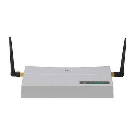
Introducing the HP ProCurve Wireless Access Point 420 Top of the Access Point Top of the Access Point HP ProCurve Wireless Access Point 420 Antennas Power, 10/100-TX Link, and Wireless Link LEDs hp procurve Link/Activity wireless access point Power 10/100-TX... -
Page 12: Leds
Introducing the HP ProCurve Wireless Access Point 420 Top of the Access Point LEDs Table 1-1. Access Point LEDs Access Point State Meaning LEDs Power The access point is receiving power. (green) The access point is NOT receiving power. Blinking* The access point is undergoing self test or downloading software. -
Page 13: Back Of The Access Point
Introducing the HP ProCurve Wireless Access Point 420 Back of the Access Point Back of the Access Point HP ProCurve Wireless Access Point 420 Antennas hp procurve wireless AP 420 na J8130A Reset Console 10/100Base-TX 3.3V Console port DC power connector... -
Page 14: Console Port
However, if you need to connect the access point to a workstation or other device that only has MDI ports, then use crossover twisted-pair cable. Ports on most HP switches have the “HP Auto MDIX” feature, which means that you can use either straight-through or crossover twisted-pair cables to connect the access point to these switches. -
Page 15: Reset Button
Introducing the HP ProCurve Wireless Access Point 420 Back of the Access Point Reset Button This button is used to reset the hardware or restore the factory defaults: To Reset the Access Point While it is Powered On – This action clears ■... -
Page 16: Access Point Features
Introducing the HP ProCurve Wireless Access Point 420 Access Point Features Access Point Features The wireless features of the Access Point 420 include: ■ supports up to 128 wireless clients ■ IEEE 802.11g Compliant – interoperable with multiple vendors precise control over signal transmission power and data rate ■... -
Page 17: Installing The Access Point 420
Installing the Access Point 420 The HP Access Point 420 is easy to install. It comes with an accessory kit that includes a bracket for mounting the access point on a wall. The bracket is designed to allow mounting the access point in a variety of locations and orientations. -
Page 18: Installation Procedures
Installing the Access Point 420 Installation Procedures Installation Procedures Summary Follow these easy steps to install your access point. The rest of this chapter provides details on these steps. Prepare the installation site (page 2-4). Make sure that the physical environment into which you will be installing the access point is properly prepared, including having the correct network cabling ready to connect to the access point and having an appropriate location for the access... -
Page 19: Installation Precautions
Installing the Access Point 420 Installation Procedures Installation Precautions: Follow these precautions when installing your HP Access Point 420: C a u t i o n s ■ Make sure that the power source circuits are properly grounded, then use the power adapter supplied with the access point to connect it to the power source. -
Page 20: Prepare The Installation Site
Installing the Access Point 420 Installation Procedures 1. Prepare the Installation Site ■ Cabling Infrastructure - Ensure that the cabling infrastructure meets the necessary network specifications. See the following table for cable types and lengths, and see appendix B, “Access Point Port and Network Cables”... -
Page 21: Verify The Access Point Passes The Self Test
Use only the AC power adapter supplied with the access point. Use of other adapters, including adapters that came with other HP network products, may result in damage to the equipment. -
Page 22: Led Behavior
Installing the Access Point 420 Installation Procedures Check the LEDs on the access point as described below. hp procurve Link/Activity wireless Power 10/100-TX Wireless access point Wireless LED Ethernet LED Power LED When the access point is powered on, it performs its diagnostic self test. -
Page 23: Mount The Access Point
Installing the Access Point 420 Installation Procedures 3. Mount the Access Point After you have verified that the access point passes the self test, you are ready to mount the access point in a stable location. The Access Point 420 can be mounted in these ways: ■... - Page 24 Installing the Access Point 420 Installation Procedures N o t e If mounting the access point in an air conditioning or heating duct, leave the cover on to aid in mounting the unit on the bracket as described in the preceding steps.
-
Page 25: Horizontal Surface Mounting
Installing the Access Point 420 Installation Procedures Horizontal Surface Mounting Place the access point on a table or other horizontal surface. The access point accessory kit provides rubber feet that can be used to help keep the access point from sliding on the surface. Attach the rubber feet to the four corners on the bottom of the access point within the embossed lines. -
Page 26: Connect The Network Cable
Installing the Access Point 420 Installation Procedures 5. Connect the Network Cable Connect the network cable, described under “Cabling Infrastructure” (page 2-4), from the network device or your patch panel to the RJ-45 port on the access point. Using the RJ-45 Connectors To connect: Push the RJ-45 plug into the RJ-45 port until the tab on the plug clicks... -
Page 27: Optional) Connect A Console To The Access Point 420
Installing the Access Point 420 Installation Procedures 7. (Optional) Connect a Console to the Access Point 420 The Access Point 420 has a full-featured, easy to use console interface for performing access point management tasks, including the following: modify the access point’s configuration to optimize access point perfor- ■... -
Page 28: Direct Console Access
DB-9 connector on both ends. Terminal connections will vary, requiring either a DB-9 or DB-25 connector, male or female. Serial cable options between an HP ProCure Wireless Access Point 420 and a PC terminal are shown in the following table. - Page 29 Password prompt. You will then see the access point console command (CLI) prompt, for example: HP ProCurve Wireless Access Point 420# If you want to continue with console management of the access point at this time, see chapter 3, “Getting Started With Access Point Configuration” for some basic configuration steps.
-
Page 30: Sample Network Topologies
■ infrastructure for wireless LANs infrastructure wireless LAN for roaming wireless PCs ■ For more topology information, see the HP network products World Wide Web site, http://www.hp.com/go/hpprocurve. Ad Hoc Wireless LAN (no access point) Ad Hoc Network with No Access Point... -
Page 31: Infrastructure Wireless Lan
Installing the Access Point 420 Sample Network Topologies Infrastructure Wireless LAN Wired LAN Extension to Wireless Adapters File Server Desktop PC Notebook with wireless PC Card Adapter Switch Access Point 420 PC with wireless PCI Adapter The Access Point 420 is designed to provide access to a wired LAN for wireless clients. -
Page 32: Infrastructure Wireless Lan For Roaming Wireless Pcs
Installing the Access Point 420 Sample Network Topologies Infrastructure Wireless LAN for Roaming Wireless PCs Seamless Roaming for Wireless Clients File Server Desktop PC Switch Wireless Client Switch Access Point 420 Wireless Client <BSS2> Access Point 420 <BSS1> <ESS> Wireless Client The Basic Service Set (BSS) defines the communications domain for each access point and its associated wireless clients. - Page 33 Extended Service Set (ESS). By placing the access points so that a continuous coverage area is created, wireless users within this ESS can roam freely. All HP wireless network cards, adapters, and access points within a specific ESS must be configured with the same SSID.
- Page 34 — This page is intentionally unused. —...
-
Page 35: Getting Started With Access Point Configuration
C a u t i o n The country code for the HP ProCurve Wireless Access Point 420 na (J8130A) sold in the United States and Canada is fixed in the firmware and cannot be changed. -
Page 36: Using The Command Line Interface
Type username username to create a user name for the manager, where username can consist of 3 to 16 alphanumeric characters and is case sensitive. (Note that only one user name is allowed for the access point.) HP ProCurve Access Point 420(config)#username admin HP ProCurve Access Point 420(config)#... - Page 37 Check with your system administrator to obtain an IP address that is compatible with your network. HP ProCurve Access Point 420(if-ethernet)#no ip dhcp HP ProCurve Access Point 420(if-ethernet)#ip address 192.168.1.1 255.255.255.0 192.168.1.254...
- Page 38 =========================================================== HP ProCurve Access Point 420# 10. If you are using the HP ProCurve Wireless Access Point 420 na (J8130A) model sold in the United States, radio channels 1 - 11 are the only options supported under FCC regulations, and cannot be changed. However, if...
- Page 39 HP ProCurve Access Point 420#configure Enter configuration commands, one per line. End with CTRL/Z HP ProCurve Access Point 420(config)#interface wireless g Enter Wireless configuration commands, one per line. HP ProCurve Access Point 420(if-wireless g)# 12.
- Page 40 Getting Started With Access Point Configuration Here is some information on the basic IP address and wireless configuration parameters. For more information on these fields, see the Management and Configuration Guide, which is on the Documentation CD-ROM that came with your access point: Parameter Default Username...
-
Page 41: Where To Go From Here
Getting Started With Access Point Configuration Where to Go From Here The above procedure, using the CLI, configured your access point with a manager password, IP address, and subnet mask. As a result, with the proper network connections, you can now manage the access point from a PC equipped with Telnet or a web browser interface. -
Page 42: Using The Ip Address For Remote Access Point Management
(CLI) prompt, for example: Username: admin Password: HP ProCurve Access Point 420# Enter ? to see a list of commands that can be executed at the prompt. Entering any command followed by ? displays a list of options that are available at that point in the command entry. - Page 43 Getting Started With Access Point Configuration Using the IP Address for Remote Access Point Management The operating systems, web browsers, and Java support required to manage the access point through the browser interface are listed in the following table: Operating System Internet Netscape Other...
- Page 44 Getting Started With Access Point Configuration Using the IP Address for Remote Access Point Management A typical web browser interface screen is shown in the next illustration. For more information on using the web browser interface, please see the Management and Configuration Guide, which is on the Documentation CD-ROM that came with your access point.
-
Page 45: Using An External Antenna With The Access Point 420
Access Point 420. P r o f e s s i o n a l Only the HP antennas listed in this guide are permitted to be connected to the I n s t a l l a t i o n Access Point 420. -
Page 46: External Antenna Options
Using an External Antenna with the Access Point 420 External Antenna Options External Antenna Options The Access Point 420 external antenna options are outlined in the following table: Table 4-1. Summary of External Antennas to Use With the Access Point 420 Antenna Type Part Number Mounting... -
Page 47: Installation Procedures
Using an External Antenna with the Access Point 420 Installation Procedures Installation Procedures Follow these steps to install an external antenna and connect it to the Access Point 420. C a u t i o n Never mount the access point outdoors to be near an external antenna. The access point must always be installed indoors. -
Page 48: Mount The Antenna
Using an External Antenna with the Access Point 420 Installation Procedures • For optimum coverage, mount the antenna at the center of the area with a line-of-sight path to all points within the area. • Avoid mounting next to or near building support columns or other obstructions that may cause reduced signal or null zones in parts of the coverage area. - Page 49 Using an External Antenna with the Access Point 420 Installation Procedures Note that diversity antennas have two pigtail cables. A diversity antenna includes two internal antenna elements that are identical. Both antenna pigtail cables must be connected to the access point for correct operation. Other non-diversity antennas, which have only one pigtail cable, attach to the access point’s right antenna connector.
-
Page 50: Configure The Antenna Mode And Transmit Power Control Limits
Using an External Antenna with the Access Point 420 Installation Procedures Antenna pigtail cable Screw onto access point’s Reverse SMA connector Reconnect power to the access point. N o t e Before enabling the radio with an external antenna attached, be sure to first configure the access point’s antenna mode and transmit power settings. - Page 51 Using an External Antenna with the Access Point 420 Installation Procedures laws for your region. For additional information on setting radio transmit power, refer to the Management and Configuration Guide, which is on the Documentation CD-ROM that came with your access point. 802.11b Transmit Power Control (TPC) Settings (%) External Antenna FCC/IC...
-
Page 52: Setting The Antenna Mode Using The Cli
Using an External Antenna with the Access Point 420 Installation Procedures 802.11b/g (Dual Mode) Transmit Power Control (TPC) Settings (%) External Antenna FCC/IC EU/ETSI Japan Taiwan 2 dBi Indoor Diversity, J8442A 5 dBi Indoor/Outdoor Omni, J8441A 6.5 dBi Indoor/Outdoor Directional Diversity, J8445A 7 dBi Indoor/Outdoor Directional, J8443A... -
Page 53: Setting The Antenna Mode Using The Web Interface
Using an External Antenna with the Access Point 420 Installation Procedures Setting the Antenna Mode Using the Web Interface Select the Configuration tab. Click the [ button. Port/Radio Settings] Scroll down to the External Antennas section at the bottom of the page. From the Antenna Mode drop-down menu, select Diversity or Single for the type of antenna attached to the access point. -
Page 54: Setting Transmit Power Limits Using The Web Inteface
Using an External Antenna with the Access Point 420 Installation Procedures Type interface wireless g to enter interface configuration mode. HP420(config)#interface wireless g Enter Wireless configuration commands, one per line. HP420(if-wireless g)# To set the antenna power limits, type transmit-limits followed by the low, middle, and high channel settings as given for the antenna and region in the Transmit Power Control Settings table for that radio mode (b;... - Page 55 Using an External Antenna with the Access Point 420 Installation Procedures Transmit Power Control limits for Low, Middle, and High channels. 4-11...
- Page 56 — This page is intentionally unused. —...
-
Page 57: Troubleshooting
Troubleshooting This chapter describes how to troubleshoot your HP ProCurve Wireless Access Point 420. Note that this document describes troubleshooting mostly from a hardware perspective. You can perform more in-depth troubleshooting on the Access Point 420 using the software tools available with the access point, including the full-featured console interface and the built-in web browser interface. - Page 58 For more information on possible network problems and their solutions, refer to the technical note “Troubleshooting LAN Performance and Intermittent Connectivity Problems”, which can be found on the HP ProCurve web site, http://www.hp.com/go/hpprocurve, in the Reference Library section under http://www.hp.com/rnd/library/index.htm under “T” in the “A-Z index.”...
-
Page 59: Diagnosing With The Leds
If the power source and power cord are OK and this condition persists, the access point’s AC power adapter may have failed. Call your HP-authorized LAN dealer, or use the electronic support services from HP to get assistance. See the Customer Support/... - Page 60 Select the Status tab, then Events Log, or view the entry file on your Syslog server if one is configured. If necessary to resolve the problem, contact your HP-authorized LAN dealer, or use the electronic support services from HP to get assistance. See the Customer Support/ Warranty booklet for more information.
-
Page 61: Proactive Networking
Troubleshooting Proactive Networking Proactive Networking The following interfaces provide tests, indicators, and an event log that can be used to monitor the access point and its network connections and to help you troubleshoot: ■ A graphical web browser interface that you can use to manage your access point from a PC running a supported web browser, for example Microsoft Internet Explorer. -
Page 62: Hardware Diagnostic Tests
Troubleshooting Hardware Diagnostic Tests Hardware Diagnostic Tests Testing the Access Point by Resetting It If you believe that the access point is not operating correctly, you can reset the access point to test its circuitry and operating code. To reset an access point, either ■... -
Page 63: Testing Twisted-Pair Cabling
Troubleshooting Hardware Diagnostic Tests Then, when you reset the access point, note the messages that are displayed. Additionally, you can check the access point’s event log, which can be accessed from the web browser or a Syslog server. Testing Twisted-Pair Cabling Network cables that fail to provide a link or provide an unreliable link between the access point and the connected network device may not be compatible with the IEEE 802.3 Type 10Base-T, or 100Base-TX standards. -
Page 64: Restoring The Factory Default Configuration
Troubleshooting Restoring the Factory Default Configuration Restoring the Factory Default Configuration As part of your troubleshooting process on the Access Point 420, it may become necessary to return the access point’s configuration to the factory default settings. This process momentarily interrupts the access point’s oper- ation, clears any passwords, clears the console event log, resets the network counters to zero, performs a complete self test, and reboots the access point into its factory default configuration including deleting the IP address, if one... -
Page 65: Downloading New Access Point Software
Management and Configuration Guide, which is on the Documentation CD-ROM that came with your access point. The new access point software is made available on the HP ProCurve web site, http://www.hp.com/go/hpprocurve under “product support – software upgrades.”... - Page 66 Troubleshooting HP Customer Support Services Information Item Information Location • copy of your network topology map, in- your network records cluding network addresses assigned to the relevant devices 5-10...
-
Page 67: Physical
Specifications Physical Width: 21.83 cm (8.60 in) Depth: 13.73 cm (5.40 in) Height: 3.27 cm (1.29 in) Weight: 0.80 kg (1.76 lbs) Electrical Adapter AC voltage: 100-240 volts, 0.4A, 50/60 Hz DC voltage: 3.3 volts, 4A Power consumption: 13.2 watts PoE (DC) Input voltage: -48 VDC, 0.15A, 7.2 watts... -
Page 68: Connectors
Specifications Connectors ■ The 10/100 Mbps RJ-45 twisted-pair port is compatible with the IEEE 802.3u 100Base-TX and IEEE 802.3 Type 10Base-T standards. Note: To provide Power over Ethernet to the access point, all 4 pairs of wires must be connected for any network cable attached to this port. Safety Complies with: LVD/EN 60950... -
Page 69: Wireless
Specifications Wireless Radio Standard: IEEE 802.11b/g Radio Technology: Direct Sequence Spread Spectrum (DSSS), Orthogonal Frequency Division Multiplexing (OFDM) Data Rate: 1, 2, 5.5, 6, 9, 11, 12, 18, 24, 36, 48, 54 Mbps per channel Operating Frequency: 2.4 ~ 2.4835 GHz (US, Canada, ETSI) 2.4 ~ 2.497 GHz (Japan) Maximum Channels: FCC/IC: 1-11, ETSI: 1-13, MKK: 1-13 (802.11g), 1-14 (802.11b) - Page 70 — This page is intentionally unused. —...
-
Page 71: B Access Point Port And Network Cables
N o t e Incorrectly wired cabling is the most common cause of problems for LAN communications. HP recommends that you work with a qualified LAN cable installer for assistance with your cabling requirements. Access Point Ports The fixed RJ-45 10/100Base-TX port on the access point accepts 100-ohm unshielded and shielded twisted-pair cable with RJ-45 connectors as described on the next page. -
Page 72: Twisted-Pair Cable/Connector Pin-Outs
MDI ports, then use “crossover” twisted-pair cable. Ports on most HP switches have the “HP Auto MDIX” feature, which means that you can use either straight-through or crossover twisted-pair cables to connect the access point to the switch. -
Page 73: Straight-Through Twisted-Pair Cable For 10 Mbps Or 100 Mbps Network Connections
Access Point Port and Network Cables Twisted-Pair Cable/Connector Pin-Outs Straight-Through Twisted-Pair Cable for 10 Mbps or 100 Mbps Network Connections Because the 10/100 port on the access point uses an MDI pin configuration, you must use “straight-through” cable for network connections to hubs or switches that only have MDI-X ports. -
Page 74: Crossover Twisted-Pair Cable For 10 Mbps Or 100 Mbps Network Connection
Access Point Port and Network Cables Twisted-Pair Cable/Connector Pin-Outs Crossover Twisted-Pair Cable for 10 Mbps or 100 Mbps Network Connection Because the 10/100 port on the access point uses an MDI pin configuration, you must use “crossover” cable for network connections to PCs, servers or other end nodes that only have MDI ports. -
Page 75: C Safety And Emc Regulatory Statements
Safety and EMC Regulatory Statements Safety Information Documentation reference symbol. If the product is marked with this symbol, refer to the product documentation to get more information about the product. WARNING A WARNING in the manual denotes a hazard that can cause injury or death. - Page 76 Safety and EMC Regulatory Statements Safety Information Regulatory Model Identification Number For regulatory identification purposes, this product has been assigned a Regulatory Model Number (RMN). The RMN for your product is RSVLC- 0301. The RMN should not be confused with the marketing name (Wireless Enterprise Access Point 420) or the Product Number (J8130A, J8131A).
- Page 77 Safety and EMC Regulatory Statements Informations concernant la sécurité Informations concernant la sécurité Symbole de référence à la documentation. Si le produit est marqué de ce symbole, reportez-vous à la documentation du produit afin d'obtenir des informations plus détaillées. WARNING Dans la documentation, un WARNING indique un danger susceptible d'entraîner des dommages corporels ou la mort.
-
Page 78: Hinweise Zur Sicherheit
Safety and EMC Regulatory Statements Hinweise zur Sicherheit Hinweise zur Sicherheit Symbol für Dokumentationsverweis. Wenn das Produkt mit diesem Symbol markiert ist, schlagen Sie bitte in der Produktdokumentation nach, um mehr Informationen über das Produkt zu erhalten. WARNING Eine WARNING in der Dokumentation symbolisiert eine Gefahr, die Verletzungen oder sogar Todesfälle verursachen kann. -
Page 79: Considerazioni Sulla Sicurezza
Safety and EMC Regulatory Statements Considerazioni sulla sicurezza Considerazioni sulla sicurezza Simbolo di riferimento alla documentazione. Se il prodotto è contras- segnato da questo simbolo, fare riferimento alla documentazione sul prodotto per ulteriori informazioni su di esso. WARNING La dicitura WARNINGdenota un pericolo che può causare lesioni o morte. -
Page 80: Consideraciones Sobre Seguridad
Safety and EMC Regulatory Statements Consideraciones sobre seguridad Consideraciones sobre seguridad Símbolo de referencia a la documentación. Si el producto va marcado con este símbolo, consultar la documentación del producto a fin de obtener mayor información sobre el producto. WARNING Una WARNING en la documentación señala un riesgo que podría resultar en lesiones o la muerte. -
Page 81: Safety Information
Safety and EMC Regulatory Statements Safety Information (Japan) Safety Information (Japan) - Page 82 Safety and EMC Regulatory Statements Safety Information (China) Safety Information (China)
-
Page 83: Emc Regulatory Statements
Safety and EMC Regulatory Statements EMC Regulatory Statements EMC Regulatory Statements Notice for U.S.A. Manufacturer's FCC Declaration of Conformity Statement Tested to Comply with FCC Standards Product No: J8130A FCC ID No: HEDWA4101ACCAA Manufacturer: Hewlett-Packard Company 3000 Hanover Street Palo Alto, CA 94304-1185 USA Phone: 650-857-1501 For questions regarding this declaration, contact the Product Regulations... -
Page 84: Notice For Canada
Safety and EMC Regulatory Statements EMC Regulatory Statements The FCC requires the user to be notified that any changes or modifications made to the device that are not expressly approved by the Hewlett-Packard Company may void the user's authority to operate the equipment. Warning: Exposure to Radio Frequency Radiation The radiated output power of this device is below the FCC radio exposure limits. -
Page 85: Notice For European Community
For up-to-date information on worldwide country authorizations, power levels and usage restrictions, please visit http://www.hp.com/go/ hpprocurve. Click on technical support, then manuals. Select your wire- less product and open the document Wireless Radio Country Approvals Matrix. -
Page 86: Eu Declaration Of Conformity
Manufacturer's Name: Hewlett-Packard Company Manufacturer's Address: 8000 Foothills Blvd. Roseville, CA 95747-5502 U.S.A. declares, that the product Product Name: HP Procurve Wireless Access Point 420 Product Number(s): J8131A Regulatory Model: RSVLC-0301 conforms to the following Product Specifications: Safety: EN 60950:2000 / IEC 60950:1999... -
Page 87: Notice For Japan
Safety and EMC Regulatory Statements EMC Regulatory Statements Notice for Japan C-13... - Page 88 — This page is intentionally unused. —...
-
Page 89: Index
Index Numerics basic troubleshooting tips … 5-1 blinking LEDs 10/100Base-TX error indications … 5-3 connections, length limitations … 2-4 buttons ports, cables used with … 2-4 Reset button … 1-7 10/100Base-TX port location on access point … 1-5 10/100-T LED … 1-4 behaviors …... - Page 90 console features checking messages during access point … 1-8 troubleshooting … 5-6 console … 2-11 command line interface … 3-2 front of access point displaying the CLI prompt … 2-13 Reset button … 1-7 features … 2-11 full-duplex fixed configuration how to connect in-band …...
- Page 91 location for the access point, considerations … 2-4, ports 10/100Base-TX, location on access point … 1-5 lock connecting to … 2-10 location on access point … 1-5 console … 2-11 network connections … 2-10 power connector … 1-6 Power LED … 1-4 MDI-X to MDI network cable …...
- Page 92 specifications troubleshooting … 5-1 connectors … A-2 basic tips … 5-1 electrical … A-1 checking the console messages … 5-6 emmissions … A-2 checking the LEDs … 5-6 environmental … A-1 common network problems … 5-1 physical … A-1 connecting to fixed full-duplex devices … 5-1 safety …...
- Page 94 Technical information in this document is subject to change without notice. ©Copyright 2002, 2004 Hewlett-Packard Development Company, L.P. Reproduction, adaptation, or translation without prior written permission is prohibited except as allowed under the copyright laws. Printed in Taiwan May 2004 Manual Part Number 5990-6005 *5990-6005*...