Table of Contents
Advertisement
Quick Links
Advertisement
Chapters
Table of Contents
Troubleshooting

Related Manuals for Ricoh D096


Summary of Contents for Ricoh D096
- Page 1 D096 SERVICE MANUAL 005627MIU...
- Page 5 D096 SERVICE MANUAL 005627MIU...
- Page 7 It is the reader's responsibility when discussing the information contained within this document to maintain a level of confidentiality that is in the best interest of Ricoh Americas Corporation and its member companies. NO PART OF THIS DOCUMENT MAY BE REPRODUCED IN ANY FASHION AND DISTRIBUTED WITHOUT THE PRIOR PERMISSION OF RICOH AMERICAS CORPORATION.
- Page 9 WARNING Service Manual contains information regarding service techniques, procedures, processes and spare parts of office equipment distributed by Ricoh Americas Corporation. Users of this manual should be either service trained or certified by successfully completing a Ricoh Technical Training Program. Untrained uncertified users...
- Page 11 LEGEND PRODUCT COMPANY CODE GESTETNER LANIER RICOH SAVIN D096 MP 1900 LD319 MP 1900 DOCUMENTATION HISTORY REV. NO. DATE COMMENTS 04/2010 Original Printing...
-
Page 13: Table Of Contents
D096 TABLE OF CONTENTS PRODUCT INFORMATION PRODUCT INFORMATION ............1-1 SPECIFICATIONS ..................1-1 MACHINE CONFIGURATION ..............1-2 GUIDANCE FOR THOSE WHO ARE FAMILIAR WITH PREDECESSOR PRODUCTS ..................... 1-3 OVERVIEW ....................1-4 ... - Page 14 EXPOSURE GLASS/DF EXPOSURE GLASS ........ 4-10 4.4.2 LENS BLOCK ................. 4-11 4.4.3 LAMP STABILIZER BOARD AND EXPOSURE LAMP ....4-12 4.4.4 SCANNER MOTOR ................ 4-13 4.4.5 SCANNER HOME POSITION SENSOR......... 4-14 D096...
- Page 15 IMAGE TRANSFER ROLLER ............4-43 4.8.2 IMAGE DENSITY SENSOR ............4-44 FUSING ....................4-45 4.9.1 FUSING UNIT ................. 4-45 4.9.2 THERMISTOR ................4-45 4.9.3 FUSING LAMPS ................4-46 D096...
- Page 16 5.2.7 NVRAM DATA UPLOAD/DOWNLOAD (SP 5824/5825) ....5-15 5.2.8 FIRMWARE UPDATE PROCEDURE ..........5-17 5.2.9 TEST PATTERN PRINT (SP 5902 1) ..........5-19 5.2.10 PAPER JAM COUNTERS (SP 7504) ......... 5-21 D096...
- Page 17 Recommendation ................. 7-2 7.1.2 ENERGY SAVE EFFECTIVENESS ..........7-3 D096 SERVICE MANUAL APPENDICES SEE D096 SERVICE MANUAL APPENDICES SECTION FOR DETAILED TABLE OF CONTENTS DF 2000 (B813) SEE SECTION B813 FOR DETAILED TABLE OF CONTENTS D096...
-
Page 19: Product Information
PRODUCT INFORMATION APPENDIX: SPECIFICATIONS B813 DOCUMENT FEEDER DF2000 INSTALLATION APPENDIX: PREVENTIVE MAINTENANCE PREVENTIVE MAINTENANCE APPENDIX: TROUBLESHOOTING GUIDE REPLACEMENT AND ADJUSTMENT APPENDIX: SP MODE TABLES SERVICE TABLES TROUBLESHOOTING ENERGY SAVING... -
Page 21: Read This First
Read This First Safety Notices Important Safety Notices Prevention of Physical Injury Before disassembling or assembling parts of the copier and peripherals, make sure that the power cord is unplugged. The wall outlet should be near the copier and easily accessible. Note that some components of the copier and the paper tray unit are supplied with electrical voltage even if the main power switch is turned off. -
Page 22: Handling Toner
Handling Toner Work carefully when removing paper jams or replacing toner bottles or cartridges to avoid spilling toner on clothing or the hands. If toner is inhaled, immediately gargle with large amounts of cold water and move to a well ventilated location. If there are signs of irritation or other problems, seek medical attention. -
Page 23: Symbols And Abbreviations
Use of controls, or adjustment, or performance of procedures other than those specified in this manual may result in hazardous radiation exposure. WARNING FOR LASER UNIT WARNING: Turn off the main switch before attempting any of the procedures in the Laser Unit section. -
Page 25: Product Information
PRODUCT INFORMATION R E V I S I O N H I S T O RY P a ge D a t e A d de d /U pd at e d /N ew None... -
Page 27: Specifications
Specifications 1. PRODUCT INFORMATION 1.1 SPECIFICATIONS See "Appendices" for the following information: General Specifications Supported Paper Size Optional Equipment D096... -
Page 28: Machine Configuration
Machine Configuration 1.2 MACHINE CONFIGURATION Unit/Component Machine Code Diagram Copier (1-tray non-duplex model) D096 Platen cover (optional) B406 Copier ADF (optional) B813 Accessibility Handle Type A (optional) B272 D096... -
Page 29: Guidance For Those Who Are Familiar With Predecessor Products
1.3 GUIDANCE FOR THOSE WHO ARE FAMILIAR WITH PREDECESSOR PRODUCTS The D096 model is successor models to the B245 model. If you have experience with the predecessor products, the following information will be of help when you read this manual. -
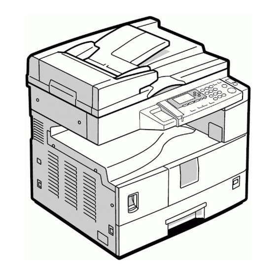
Page 30: Overview
Overview 1.4 OVERVIEW 1.4.1 COMPONENT LAYOUT D096... - Page 31 9. Hot Roller 24. Polygon Mirror Motor 10. Pressure Roller 25. Laser Unit 11. OPC Drum 26. Toner Supply Bottle Holder 12. Image Density Sensor 27. Exit Roller 13. Registration Roller 28. 3rd Mirror 14. Registration Sensor 29. Scanner HP Sensor D096...
-
Page 32: Paper Path
Overview 1.4.2 PAPER PATH Original Feed from ADF Paper Feed from Tray 1 Paper Feed from By-pass Tray D096... -
Page 33: Drive Layout
Overview 1.4.3 DRIVE LAYOUT 1. Scanner Motor 5. Development Roller 2. Main Motor 6. By-pass Feed Clutch 3. Hot Roller 7. Paper Feed Clutch 4. OPC Drum 8. Registration Clutch D096... -
Page 35: Installation
INSTALLATION R E V I S I O N H I S T O RY P a ge D a t e A d de d /U pd at e d /N ew None... -
Page 37: Installation Requirements
10°C to 32°C (50°F to 89.6°F) Humidity Range: 15% to 80% RH Ambient Illumination: Less than 1,500 lux (do not expose to direct sunlight) Ventilation: 3 times/hr/person or more Ambient Dust: Less than 0.075 mg/m (2.0 x 10⁻⁶ oz/yd3) D096... -
Page 38: Machine Level
Place the machine on a strong and level base. (Inclination on any side should be no more than 5 mm.) Do not place the machine where it is subjected to strong vibrations. 2.1.2 MACHINE LEVEL Front to back: Within 5 mm (0.2") of level Right to left: Within 5 mm (0.2") of level D096... -
Page 39: Minimum Space Requirements
Avoid multi-wiring. Be sure to ground the machine Input voltage: North and South America, Taiwan: 110 – 120 V, 60 Hz, 12 A Europe, Asia: 220 – 240 V, 50/60 Hz, 7 A D096... -
Page 40: Copier Installation
[B]: Socket for paper tray unit (Rated voltage output max. DC24 V) 2.2.2 ACCESSORY CHECK Check that you have the accessories in this list. Description Q’ty Multi-language (-17, -27,-19, -29) NECR-English (-17) Model Name Plate (-22, -19, -29) Operating Instruction (-17, -19, -29) D096... -
Page 41: Installation Procedure
Copier Installation 2.2.3 INSTALLATION PROCEDURE Unplug the machine power cord before starting the following procedure. Remove filament tape and other padding. Open the front door and remove the toner bottle holder [A] D096... - Page 42 Distribute a pack of developer [D] to all openings equally. Do not spill the developer on the gears [E]. If you have spilled it, remove the developer by using a magnet or magnetized screwdriver. Do not turn the gear [E] too much. The developer may spill. D096...
- Page 43 To move the side guides, release the green lock on the rear side guide. 12. Install the optional ADF or platen cover. 13. Plug in the main power cord and turn on the main switch. 14. Activate the SP mode and execute "Devlpr Initialize" (SP 2214 1). D096...
- Page 44 16. Activate the User Tools and select the menu "Language." 17. Specify a language. This language is used for the operation panel. 18. Load the paper in the paper tray and make a full size copy, and make sure the side-to-side and leading edge registrations are correct. D096...
-
Page 45: Platen Cover Installation
2.3 PLATEN COVER INSTALLATION 2.3.1 ACCESSORY CHECK Check that you have the accessories indicated below. Description Q’ty Stepped Screw 2.3.2 INSTALLATION PROCEDURE Unplug the machine power cord before starting the following procedure. Install the platen cover ( x 2). D096... -
Page 46: Adf Installation
2.4.1 ACCESSORY CHECK Check the quantity and condition of the accessories against the following list. Description Q'ty Scale Guide DF Exposure Glass Stud Screw Fixing Screw Original Size Decal Screwdriver Tool Attention Decal - Top Cover Stamp Cartridge Installation Procedure D096 2-10... -
Page 47: Installation Procedure
Peel off the backing [D] of the double-sided tape attached to the rear side of the scale guide [E], then install the scale guide ( x 2 [removed in step 2]). Install the two stud screws [F]. Mount the ADF on the copier, and then slide it to the front. 2-11 D096... - Page 48 ADF Installation Secure the ADF unit with the fixing screws [G]. Connect the cable [H] to the copier. Attach the appropriate scale decal [I] as shown. 10. Attach an attention decal to the top cover. D096 2-12...
- Page 49 12. Turn the main power switch on. Then check if the document feeder works properly. 13. Make a full size copy, and check that the side-to-side and leading edge registrations are correct. If they are not, adjust the side-to-side and leading edge registrations. ( p.4-63). 2-13 D096...
-
Page 50: Anti-Condensation Heater Installation
Remove the left cover. Pass the connector [A] through the opening [B]. Install the anti-condensation heater [C], as shown. Join the connectors [A, D]. Clamp the harness with the clamp [E]. Reinstall the left cover and exposure glass. D096 2-14... -
Page 51: Tray Heater
Unplug the machine power cord before starting the following procedure. 2.6.1 TRAY HEATER Remove the 1st tray cassette [A]. Remove the rear cover. Pass the connector [B] through the opening [C] and install the tray heater [D] ( x 1). 2-15 D096... - Page 52 Tray Heater Install the relay harness [E]. Fix the harness with the clamp [F]. Reinstall the 1st tray cassette and the rear cover. D096 2-16...
-
Page 53: Accessibility Handle Installation
Remove the paper tray [A] from the main copier. Turn the paper tray over to the opposite side. Lower the paper tray grip handle [B] into the paper tray slot as shown with the arrow in the above illustration. 2-17 D096... - Page 54 Accessibility Handle Installation Attach the grip handle to the paper tray ( x 2) as shown above. Put the paper tray back into the machine. D096 2-18...
-
Page 55: Preventive Maintenance
PREVENTIVE MAINTENANCE R E V I S I O N H I S T O RY P a ge D a t e A d de d /U pd at e d /N ew None... -
Page 57: Pm Tables
PM Tables 3. PREVENTIVE MAINTENANCE 3.1 PM TABLES See "Appendices" for the "PM Tables". D096... -
Page 58: How To Reset The Pm Counter
After preventive maintenance work, reset the PM counter (SP 7804 1) as follows. Activate the SP mode. Select SP 7804 1 (Reset–PM Counter). Press the OK key [A]. The message "Execute" shows. Press the button [B] below the message "Execute." D096... - Page 59 How to Reset the PM Counter The messages "Execute?" followed by "Cancel" and "Execute" show. To reset the PM counter, press the button [C] below the message "Execute." Wait until the message "Completed" shows. Quit the SP mode. D096...
-
Page 61: Replacement And Adjustment
REPLACEMENT AND ADJUSTMENT R E V I S I O N H I S T O RY P a ge D a t e A d de d /U pd at e d /N ew None... -
Page 63: General Cautions
Make sure to not bend or crease the exposure lamp’s ribbon cable. Do not disassemble the lens unit. This will cause the lens and copy image to get out of focus. Do not turn any of the CCD positioning screws. This will put the CCD out of position. D096... -
Page 64: Laser Unit
If the optional tray heater or optics anti-condensation heater is installed, keep the machine's power cord plugged in even while the main switch is off, to keep the heater(s) energized. D096... -
Page 65: Special Tools And Lubricants
4.2 SPECIAL TOOLS AND LUBRICANTS Part Number Description Q’ty A0069104 Scanner Positioning Pins (4 pins/set) 1 set A2929500 Test Chart S5S (10 pcs/set) 1 set VSSM9000 FLUKE 87 Digital Multimeter N8036701 4MB Flash Memory Card A2579300 Grease Barrierta S552R 52039502 Grease G-501 D096... -
Page 66: Exterior Covers & Operation Panel
Exterior Covers & Operation Panel 4.3 EXTERIOR COVERS & OPERATION PANEL 4.3.1 REAR COVER Unplug the DF cable [A] (if installed). Rear cover [B] ( x 6) 4.3.2 COPY TRAY Copy tray [A] ( x 2) D096... -
Page 67: Upper Covers
4, x 1) Right upper cover [D] ( x 1, 3 hooks) Push the cover to the rear side to release the hooks. Top rear cover [E] ( x 1) 4.3.4 LEFT COVER Left cover [A] ( x 3) D096... -
Page 68: Front Cover
Exterior Covers & Operation Panel 4.3.5 FRONT COVER Pull out the (top) paper tray. Open the front door [A]. Front cover [B] ( x 4) 4.3.6 FRONT RIGHT COVER Open the front door [A]. Front right cover [B] ( x 1) D096... -
Page 69: Right Rear Cover
"Upper Covers") Open the right door. Right rear cover [A] ( x 1) 4.3.8 RIGHT DOOR Right rear cover (see above) Open the right door [A]. Open the clamps [B] and disconnect the two connectors [C]. Right door D096... -
Page 70: By-Pass Tray
Front-side clip ring [A] Front-side pin [B] (You can push the pin from behind the right door.) Front-side tray holder arm [C] Remove the rear-side clip ring, pin, and tray holder arm in the same manner. By-pass tray [D] D096... -
Page 71: Platen Cover Sensor
Exterior Covers & Operation Panel 4.3.10 PLATEN COVER SENSOR Top rear cover Platen cover sensor [A] ( x 1) D096... -
Page 72: Scanner Unit
- DF Exposure Glass - Front upper left cover ( p.4-5 "Upper Covers") Left scale [A] DF exposure glass [D] Make sure that the mark [E] is on the bottom at the front end when reinstall the exposure glass. D096 4-10... -
Page 73: Lens Block
"Exposure Glass/DF Exposure Glass ") Lens cover [A] ( x 5) Disconnect the flat cable [B]. Lens block [C] ( x 4). Adjust the image quality ( p.4-58 "Copy Adjustments Printing/Scanning") after you install a new lens block. 4-11 D096... -
Page 74: Lamp Stabilizer Board And Exposure Lamp
Place one hand under the lamp stabilizer board [A] and release the hook [B]. Lamp stabilizer board ( x 2) Press the plastic latch [C] and push the front end of the lamp toward the rear. Lamp [D] (with the cable) D096 4-12... -
Page 75: Scanner Motor
1, 1 spring, 1 belt) Install the belt first, and then set the spring when you reassemble. Fasten the leftmost screw (viewed from the rear), and fasten the other two screws. Adjust the image quality after you install the motor. 4-13 D096... -
Page 76: Scanner Home Position Sensor
Left upper cover, top rear cover. Exposure glass, DF exposure glass (if installed) ( p.4-10 "Exposure Glass/DF Exposure Glass ") Disconnect the connector [A]. Scanner left lid [B] ( x 7) Sensor tape [C]. Scanner home position sensor [D] D096 4-14... -
Page 77: Adjusting Scanner Positions
To adjust the belt contact points on the scanner bracket (See "Adjusting the Second Scanner Contact Points" below.) The two actions above have the same objectives--to align the following holes and marks: The adjustment holes [H] [J] in the first scanner 4-15 D096... - Page 78 10. Check that the scanner belts [B] [C] [G] [H] are properly set between the bracket and the 1st scanner. 11. Tighten the screws [A] [F]. 12. Remove the positioning tools. 13. Reassemble the machine and check the operation. D096 4-16...
- Page 79 Operation panel, top rear cover ( p.4-5 "Upper Covers"). Exposure glass ( p.4-10 "Exposure Glass/DF Exposure Glass ") Controller bracket [A] ( x 3) Disconnect the platen-cover-sensor connector [B]. Rear frame [C] ( x 7) Scale bracket [D] ( x 2) 4-17 D096...
- Page 80 12. The alignment marks on the frames 13. Insert the positioning tools [B] [C] through the holes and marks. 14. Check that the scanner belts are properly set in the brackets. 15. Remove the positioning tools. 16. Reassemble the machine and check the operation. D096 4-18...
-
Page 81: Laser Unit
4.5 LASER UNIT The laser beam can seriously damage your eyes. Be absolutely sure that the main power switch is off and that the machine is unplugged before you access the laser unit. 4.5.1 LOCATION OF CAUTION DECAL 4-19 D096... -
Page 82: Toner Shield Glass
Laser Unit 4.5.2 TONER SHIELD GLASS Open the front door. Lift the toner cartridge latch [A]. Press the toner shield glass cover [B] to the left and pull it out. Pull out the toner shield glass [C]. D096 4-20... -
Page 83: Laser Unit
4.5.3 LASER UNIT Toner shield glass. Copy tray Pull out the (upper) paper tray. Front cover Laser unit [A] ( x 2, x 4) The screw at the left front position [B] is longer than the other three. 4-21 D096... -
Page 84: Ld Unit
4.5.4 LD UNIT Do not touch the paint-locked screw [A]. The LD position is adjusted before shipment. Laser unit LD unit [B] ( x 1) Do not screw the LD unit in too tightly when you install it. D096 4-22... -
Page 85: Polygonal Mirror Motor
Laser Unit 4.5.5 POLYGONAL MIRROR MOTOR Laser unit Two rubber bushings [A] Laser unit cover [B] ( x 1) Polygonal mirror motor [C] ( x 4) After reassembling, adjust the image quality ( p.4-58 "Copy Adjustments Printing/Scanning"). 4-23 D096... -
Page 86: Laser Unit Alignment Adjustment
Install the screw (through the slot [D]) loosely into the hole beneath the slot (do not tighten the screw). Install the four screws for the laser unit loosely (do not tighten the screws). When you rotate the lever clockwise or counterclockwise by one notch of the lever, the D096 4-24... - Page 87 2, and find how much the corners should be shifted. 10. Tighten the screw [A]. 11. Tighten the screws on the laser unit. 12. Reinstall the copy tray. 13. Print the trim pattern and check the result. Do the procedure again if further adjustment is required. 4-25 D096...
-
Page 88: Pcu Section
Open the right door. Press the latch [B] and pull out the PCU [C]. Do not touch the OPC drum surface with bare hands. Load new developer ( p.4-32). Do SP 2214 to reinitialize the TD sensor when you reassemble. D096 4-26... -
Page 89: Toner Supply Motor
PCU Section 4.6.2 TONER SUPPLY MOTOR Copy tray ( p.4-5 "Upper Covers") Open the front door. Toner bottle holder ( p.4-26 "PCU") Toner supply motor [A] ( x 1) 4-27 D096... -
Page 90: Pick-Off Pawls And Toner Density Sensor
1) The toner density sensor is taped to the bottom of the PCU. Pry it off with a regular screwdriver. After reinstalling the pick-off pawls or toner density sensor, adjust the image quality p.4-33 "After Replacement or Adjustment"). D096 4-28... -
Page 91: Opc Drum
Pry out the drum retaining clip [F]. Install the clip in the same orientation (with the lip facing away from the drum shaft) when you reassemble. OPC drum [G] When reassembling, adjust the image quality ( p.4-33 "After Replacement or Adjustment"). 4-29 D096... -
Page 92: Charge Roller And Cleaning Brush
Charge roller [C] and cleaning brush [D] (with the holders and springs) Turn the gear [E] (as necessary) so that the rear holder [F] comes out. When reassembling, adjust the image quality ( p.4-33 "After Replacement or Adjustment"). D096 4-30... -
Page 93: Cleaning Blade
After installing the cleaning blade, remove some of the toner from the old blade with your finger. Apply the toner to the edge [A] of the new cleaning blade. Make sure to apply the toner evenly along full length of the new cleaning blade. 4-31 D096... -
Page 94: Developer
11. Turn the coupling in the direction of the arrow [D] to remove developer from the roller. 12. Turn the bottom part [E] over and rotate the gears to remove the developer. 13. Load new developer. 14. When reassembling, execute SP 2214 to reinitialize the TD sensor. D096 4-32... -
Page 95: After Replacement Or Adjustment
If using A3 or 11" x 17" paper, make 2 copies/prints. To make solid black prints, use SP 5902 pattern 8. Step 7 is required only after parts replacement or adjustment. You do not need to make sky-shot (or solid black) copies after you replace the developer. 4-33 D096... -
Page 96: Paper Feed Section
4.7.1 PAPER FEED ROLLER Paper cassette Clip [A] Push the shaft back through the opening, and tilt it up. If the black plastic bushing [B] comes off, make sure you remount it when reinstall the shaft. Paper feed roller [C] D096 4-34... -
Page 97: Friction Pad
4.7.2 FRICTION PAD Paper cassette Clip [A] Push the shaft back through the opening, so that the roller moves clear of the friction pad. Friction pad [B] 4.7.3 PAPER END SENSOR Paper cassette Paper end sensor [A] ( x 1) 4-35 D096... -
Page 98: Exit Sensor
Paper Feed Section 4.7.4 EXIT SENSOR Open the right door. Front right cover Guide [A] ( x 2) Exit sensor bracket [B] ( x 1) Exit sensor [C] ( x 1) D096 4-36... -
Page 99: By-Pass Feed Roller And Paper End Sensor
When you do so, use caution not to place too much load on the cable. Sensor holder [A] By-pass paper end sensor [B] ( x 1) By-pass feed roller [C] 4-37 D096... -
Page 100: Registration Roller
Unhook the springs [A] and [B] at the rear and front sides. Guide support [C] and guide [D] ( x 1, x 1) Bushing [E] ( x 1) 10. Gear [F] and bushing [G] ( x 1) 11. Registration roller [H] with the image transfer unit [I] D096 4-38... -
Page 101: By-Pass Paper Size Switch
When reinstalling the switch: Move the paper guides to their middle position (about halfway between fully open and fully closed), and install the round gear so that the hole in the gear [D] aligns with the peg [E] on the sliding gear. 4-39 D096... -
Page 102: Registration Clutch
4.7.8 REGISTRATION CLUTCH Rear cover High-voltage power supply board (with the bracket) [A] ( x 4, all connectors) Registration clutch [B] ( x 1, x 1) 4.7.9 REGISTRATION SENSOR Open the right door. Registration sensor [A] ( x 1) D096 4-40... -
Page 103: Paper Feed Clutch And By-Pass Feed Clutch
2 ) Paper feed clutch [B] ( x 1) By-pass feed clutch [C] ( x 1) Make sure that the rotation-prevention tabs [D] on the clutches fit correctly into the corresponding openings on the clutch cover when you reinstall. 4-41 D096... -
Page 104: Paper Size Switch
Paper Feed Section 4.7.11 PAPER SIZE SWITCH Paper cassette Switch cover [A] ( x 1) Paper size switch [B] ( x 1) D096 4-42... -
Page 105: Image Transfer
Open the right door. Lift the plastic holders [A] with the image transfer roller [B]. Leave the springs under the holders. Make sure that the pegs [C] on the holders [D] engage with the springs when you reassemble. 4-43 D096... -
Page 106: Image Density Sensor
Image Transfer 4.8.2 IMAGE DENSITY SENSOR Open the right door. Plastic cover [A] Image transfer roller ( p.4-43) Push down on the notch [B] to free the sensor. Image density sensor [C] ( x 1) D096 4-44... -
Page 107: Fusing
Turn off the main switch, and unplug the machine. Front right cover Open the right door. Fusing unit [A] ( x 2, x 4) 4.9.2 THERMISTOR Fusing unit (see above) Thermistors [A] ( x 1, x 1) 4-45 D096... -
Page 108: Fusing Lamps
Fusing lamp with the connector (550W) [F] ( x 2) Check that the front ends of the two lamps fit in the front holding plate when you reassemble. They do not fit in there if you arrange the two lamps incorrectly. D096 4-46... -
Page 109: Sm D096
Roller guard [A] ( x 3) Metal holders [B] (1 holder for each) Hot roller stripper pawls [C] (1 spring for each) 4.9.5 HOT ROLLER Hot roller stripper pawls (See above) Hot roller [A] (2 C-rings, 1 gear, 2 bearings) 4-47 D096... -
Page 110: Thermostat
Fusing 4.9.6 THERMOSTAT Hot roller (See above) Thermostat [A] ( x 2 for each) D096 4-48... -
Page 111: Pressure Roller And Bushings
4.9.7 PRESSURE ROLLER AND BUSHINGS Separate the hot roller section from the pressure roller section ( p.4-46 "Fusing Lamps"). Fusing entrance guide [A] ( x 2) 2 springs [B] 2 pressure arms [C] 2 Bushings [D] Pressure roller [E] 4-49 D096... -
Page 112: Nip Band Width Adjustment
If the band is not as described above, change the position of the spring hooks [C] (one on each side), and then check the band again. The higher hook position produces greater tension. D096 4-50... -
Page 113: Cleaning Roller
Fusing 4.9.9 CLEANING ROLLER Pressure roller and bushings ( p.4-49) Cleaning roller [A] 4-51 D096... -
Page 114: Other Replacements
Other Replacements 4.10 OTHER REPLACEMENTS 4.10.1 QUENCHING LAMP Quenching lamp [A] ( x 1) 4.10.2 HIGH-VOLTAGE POWER SUPPLY BOARD Rear cover High-voltage power supply board [A] ( x 2, 3 standoffs, all connectors) D096 4-52... -
Page 115: Bicu (Base-Engine Image Control Unit)
Remove the NVRAM [B] from the old BICU and install it on the new BICU when you replace the BICU. The NVRAM keeps machine-specific data. 4.10.4 MAIN MOTOR Rear cover Main motor [A] ( x 4, x 1) 4-53 D096... -
Page 116: Left Exhaust Fan
Make sure that the arrow on the fan [C] points the outside of the copier when you reassemble. The arrow indicates the direction of the air current. 4.10.6 PSU (POWER SUPPLY UNIT) Left cover PSU [A] (All connectors, x 6) D096 4-54... -
Page 117: Gearbox
BICU (with the bracket) [C] ( x 6) If you have difficulty to remove the bracket, remove the screw at the middle of the crosspiece (see step 6). Main motor Crosspiece [D] ( x 3) Registration clutch 4-55 D096... - Page 118 Do not change the position of the spring [G] and make sure that the bushing [H] on the PCU drive shaft is in the correct position you when you reassemble. You can adjust its position by rotating the gear [I] seen from the opening of the gearbox. - Gear Arrangement in the Gearbox - D096 4-56...
- Page 119 If the gears fall out, start by finding gear number 1 and installing it onto location number 1 (setting it into place so that the side with the printed number stays visible). Then install the remaining gears (2 to 12) in the same way. 4-57 D096...
-
Page 120: Copy Adjustments Printing/Scanning
First or second scanner Lens Block Scanner Motor Polygonal Mirror Motor Paper Tray Paper Side Fence For detailed explanations about how to access and use the SP modes, see Section 5. D096 4-58... -
Page 121: Printing
SP mode Specification All Trays SP 1001 1 By-pass feed SP 1001 2 2 ± 1.5 mm 1st tray SP 1002 1 By-pass feed SP 1002 5 A: Leading Edge Registration B: Side-to-side Registration - Blank Margin - 4-59 D096... -
Page 122: Scanning
- Main Scan Magnification - Print the single-dot grid pattern (SP 5902 1). Check the magnification (the grid size should be 2.7 x 2.7 mm), and if necessary use SP 2998 to adjust it. The specification is 100 ± 1%. 4.11.2 SCANNING D096 4-60... - Page 123 Check the leading edge and side-to-side registration, and adjust as necessary with the following SP modes. SP mode Specification Leading edge SP 4010 2 ± 1.5 mm Side-to-side SP 4011 A: Leading edge registration B: Side-to-side registration - Magnification - A: Main scan magnification B: Sub-scan magnification 4-61 D096...
- Page 124 Place 10 sheets of new A4/LTR paper (sideways, LEF) or new A3/DLT paper on the exposure glass, and close the platen cover or the ADF. Enter SP 4428 1 and select "1: YES". The machine automatically adjusts the standard white density. D096 4-62...
-
Page 125: Adf Image Adjustment
Place the temporary test chart on the ADF and make a copy from one of the feed stations. Check the registrations, and adjust as necessary with the appropriate SP modes, as follows. SP mode Side-to-side registration SP 6006 1 Leading edge registration SP 6006 2 Blank margin for the trailing edge SP 6006 3 4-63 D096... - Page 126 Make a temporary test chart as shown above, with A3/11" x 17" paper. Place the temporary test chart on the ADF and make a copy from one of the feed stations. Check the registration, and if necessary adjust it with SP 6006 5. The specification is ±1.0%. D096 4-64...
-
Page 127: Service Tables
SERVICE TABLES R E V I S I O N H I S T O RY P a ge D a t e A d de d /U pd at e d /N ew None... -
Page 129: Service Program Mode
See "Appendices" for the following information: System SP Tables 5.1.2 HOW TO ENTER THE SP MODE The following two modes are available: SP Mode (Service Program Mode): The SP Mode includes the programs that are necessary for standard maintenance work. D096... - Page 130 You cannot end the SP mode while the copy mode is activated. Quitting Programs/Ending (S)SP Mode Press the key or the "Cancel" key to quit the program. You can end the SP mode by pressing one of these keys several times. D096...
-
Page 131: Using Sp Modes
Using SP Modes 5.2 USING SP MODES 5.2.1 ADJUSTING REGISTRATION AND MAGNIFICATION To adjust the registration and magnification, you need to use several service programs. The chart shows an example of the procedure to adjust the machine in the basic configuration. D096... -
Page 132: Id Sensor Error Analysis (Sp 2221)
ID sensor dirty display) power (979) is ID-sensor light Drum not get charged applied SP 2221 4 Vsdp No Error Conditions SP 2221 5 Vt Vt > 4.5V or TD sensor defective Vt < 0.2V SP 2221 6 Vts D096... -
Page 133: Memory Clear
Print out all SMC data lists ( SMC Print (SP 5990)). Be sure to print out all the lists. You have to manually change the SP settings if the NVRAM data upload ends abnormally. Select SP 5801 2. Press the OK key. D096... - Page 134 Refer to the SMC lists, and enter any values that differ from the factory settings. Double-check the values for SP 4901. 10. Adjust the standard white level (SP 4428). 11. Initialize the TD sensor (SP 2214). 12. Check the copy quality and the paper path. D096...
-
Page 135: Input Check (Sp 5803)
Duplex Inverter S Paper detected Not detected Duplex Entrance S Paper detected Not detected Duplex Exit S Paper detected Not detected By-pass PE S Paper detected Not detected By-pass P Size S Upper PE S Paper detected Not detected D096... - Page 136 BK-Lift M Lock Locked Not locked Total CO Install Installed Not installed Key CO Install Installed Not installed L-Synchronization Detected Not detected DF-Position S Detected Not detected DF-Cover Open S Detected Not detected DF-Original Set S Detected Not detected D096...
- Page 137 Not set A4 LEF A4 SEF A5 LEF LT LEF A3 SEF North 8Hx13 Not set A4 LEF LT SEF LT LEF America China Not set A4 LEF B5 LEF A4 SEF A5 LEF B4 SEF -- A3 SEF D096...
- Page 138 Using SP Modes Paper Feed Unit Europe North America China By-Pass Tray 8x13 Europe North America China D096 5-10...
- Page 139 Using SP Modes - *2 Paper Amount - Near end About 25% About 75% About 100% - *3 Available Paper Feed Unit - None 2-tray paper feed unit 1-tray paper feed unit 5-11 D096...
-
Page 140: Output Check (Sp 5804)
Main Motor Forward Main Motor Reverse Quenching Lamp Toner Supply Motor Forward Fan Motor High Fan Motor Low Registration Clutch By-pass Feed Clutch Upper Feed Clutch Lower Feed Clutch BK-Low Lift Motor Up BK-Low Lift Motor Down Relay Clutch D096 5-12... - Page 141 Duplex Inv Motor Forward Duplex Trans Motor Duplex Gate Solenoid Duplex Inv Motor Hold Dup Trans Motor Hold Polygon Motor Polygon M/LD DF-Transport Motor DF-Feed Motor DF-Feed Clutch DF-Pickup Solenoid DF-Stamp Solenoid DF-Gate Solenoid 1 bin Gate Solenoid 5-13 D096...
-
Page 142: Serial Number Input (Sp 5811)
You can specify a digit ("0" to "9") or a capital letter ("A" to "Z") for the first four characters of a serial number, and you can specify a digit in the other seven characters (not capital letters). D096 5-14... -
Page 143: Nvram Data Upload/Download (Sp 5824/5825)
- NVRAM Upload (SP 5824 1) - Turn off the main switch. Remove the card cover [B] (1 rivet). Turn the face of the flash memory card [A] ("A" is printed on it) toward your left-hand 5-15 D096... - Page 144 The machine erases the current settings, then writes the new settings onto the NVRAM on the BICU board. This takes about 1 second. If downloading fails, an error message appears. If an error message appears, retry the download procedure. Turn off the main switch. Remove the memory card. D096 5-16...
-
Page 145: Firmware Update Procedure
Turn the main switch off. Remove the card cover [B] (1 rivet). Insert the flash memory card [A]. Press down the power switch on the operation panel and hold it, and turn on the main switch. Select "Execute" [C]. 5-17 D096... - Page 146 Make sure the message "End Sum..." shows. This message indicates that the program has ended normally. Turn off the main switch. Remove the flash memory card. 10. Replace the card cover [B] (1 rivet). 11. Turn the main switch on. 12. Check the operation. D096 5-18...
-
Page 147: Test Pattern Print (Sp 5902 1)
Horizontal Lines (Single Dot) Vertical Lines (Double Dot) Horizontal Lines (Double Dot) Grid Pattern (Single Dot) Grid Pattern (Double Dot) Alternating Dot Pattern Isolated one dot Black Band (Horizontal) Trimming Area Argyle Pattern (Single Dot) Grayscales (Horizontal) Grayscales (Vertical) Grayscales (Vertical/Horizontal) 5-19 D096... - Page 148 Grid Pattern (Double Dot) Black Band (Vertical, 1024 Dots) Grayscales (Horizontal, 512 Dots) Grayscales (Vertical, 256 Dots) ID Patch Cross Argyle Pattern (128-Dot Pitch) Square Gradation (64 Grades) Square Gradation (256 Grades) Grayscales (Horizontal, 32-Dot Width) Grayscales (Vertical, 32-Dot Width) D096 5-20...
-
Page 149: Paper Jam Counters (Sp 7504)
Paper does not reach the registration sensor (from the by-pass tray). Paper is caught at the registration sensor. Paper is caught at the exit sensor (previous page). Paper does not reach the exit sensor. Paper is caught at the exit sensor. 5-21 D096... -
Page 150: Smc Print (Sp 5990)
Press the OK key. The summary of the jam history shows. To view more information, select "Detail." 5.2.13 JAM HISTORY CODES Code Meaning Original does not reach the registration sensor. Original caught at the registration sensor. Short interval between originals. D096 5-22... -
Page 151: Adf Aps Sensor Output Display (Sp 6901)
Using SP Modes 5.2.14 ADF APS SENSOR OUTPUT DISPLAY (SP 6901) - Sensor Positions - Large to Small 5-23 D096... - Page 152 " LEF A5 LEF " x 11" SEF A4 SEF " x 14" " x 13" 11" x 8 " LEF A4 LEF 11" x 17" " X 8 " SEF A5 SEF — B5 SEF 1: Detected D096 5-24...
-
Page 153: Troubleshooting 6
TROUBLESHOOTING R E V I S I O N H I S T O RY P a ge D a t e A d de d /U pd at e d /N ew None... -
Page 155: Service Call Conditions 6
Service Call Conditions 6. TROUBLESHOOTING 6.1 SERVICE CALL CONDITIONS For "Service Call Conditions" information, see "Appendices". D096... -
Page 156: Sensors
Jam message will appear whenever a copy is made from the bypass tray. The Paper Jam message will appear Open whenever a copy is made (paper has not 124-2 Exit reached the sensor). (BICU) Shorted The Paper Jam message appears even if D096... - Page 157 SC392 is activated when the CPU detects an ID sensor error during developer initialization (SP 2214). However, SC392 is not displayed on the LCD but simply logged in the SC log (SMC printout), unless the technician exits SP Mode as soon as an error message is displayed. D096...
-
Page 158: Switches
The Cover Open indicator is lit even if Open doors are closed. 130-1 Front/Right Cover (BICU) The Cover Open indicator is not lit even if Shorted doors are open. Open The machine does not turn on. 281-3,4 Main (PSU) Shorted The machine does not turn off. D096... -
Page 159: Blown Fuse Conditions 6
6.3 BLOWN FUSE CONDITIONS All the fuses in the following table are on the power supply board. Rating Fuse 120 V 220 – 240 V 15A/125V 8A/250V 5A/125V 2.5A/250V 1A/250V 1A/250V 4A/250V 4A/250V 4A/250V 4A/250V 4A/250V 4A/250V 4A/250V 4A/250V D096... -
Page 160: Bicu
LED Display 6.4 LED DISPLAY 6.4.1 BICU Number Function Monitors the +5 V line for the CPU and the surrounding circuit. LED 1 Usually, this LED is blinking. D096... -
Page 161: Energy Saving 7
ENERGY SAVING R E V I S I O N H I S T O RY P a ge D a t e A d de d /U pd at e d /N ew None... -
Page 163: Energy Saver Modes
If the timers are changed, then the energy saved will be different. For example, if the timers are all set to 240 min., the grey area will disappear, and no energy is saved before 240 min. expires. D096... -
Page 164: Timer Settings
240 minutes has expired after the last job. This means that after the customer has finished using the machine for the day, energy will be consumed that could otherwise be saved. If you change the settings, the energy consumed can be measured using SP8941, as explained below. D096... -
Page 165: Energy Save Effectiveness
Find the amount of time spent in each mode (subtract the earlier measurement from the later measurement). Multiply this by the power consumption spec for each mode. Convert the result to kWh (kilowatt hours) Here is an example calculation. D096... - Page 166 508776. 520377. mode Off mode Time 11601.0 81207.0 Total Time of Data: d (min.) 17506.0 Total Time of Data: d/60min. (Hour) 291.77 Total Power Consumption of Data: e (Wmin.) 1602613.60 Total Power Consumption of Data: e /60min./1000W (KWH) 26.71 D096...
- Page 167 D096 SERVICE MANUAL APPENDICES...
- Page 169 D096 APPENDICES TABLE OF CONTENTS APPENDIX: SPECIFICATIONS ............1-1 GENERAL SPECIFICATIONS ..............1-1 SUPPORTED PAPER SIZES ..............1-6 1.2.1 ORIGINAL SIZE DETECTION ............1-6 North America, Europe, Asia, Taiwan ..........1-6 China, Korea ..................1-8 ...
-
Page 171: Appendix: Specifications
APPENDIX: SPECIFICATIONS R E V I S I O N H I S T O RY P a ge D a t e A d de d /U pd at e d /N ew None... -
Page 173: General Specifications
(but this size is not recognized by the application software): Width: 305 mm Length: 1,260 mm Paper Tray: 60 – 90 g/m , 16 – 24 lb. Copy Paper Weight: By-pass: 52 – 162 g/m , 14 – 43 lb. SM Appendix D096... - Page 174 220 – 240 V, 50/60 Hz, 7 A Full System: Not above 1.28 kW Off Mode: Not above 1 W Power Consumption: Full system - Maximum possible power consumption (any combination of mainframe and options), excluding optional heaters. D096 SM Appendix...
- Page 175 A3 SEF/11" × 17" 1-sided Memory copy A4 LEF/11" x 8 " 1-sided A3 SEF/11" × 17" DF 1-to-1 A4 LEF/11" x 8 " Measurement Conditions: Figures are for one-sided original to one-sided copy except where stated otherwise 100% size SM Appendix D096...
- Page 176 100 sheets (sheets up to 432 mm [17"]) 40 postcards 10 envelopes Copy weight: 80 g/m (20 lb.) Toner Replenishment: Cartridge replacement (260 g/cartridge) Platen cover Auto document feeder Optional Equipment: Tray heater Optics anti-condensation heater Universal Handle D096 SM Appendix...
- Page 177 General Specifications 9k copies (A4 LEF, 6% full black, 1 to 2 copying, normal text Toner Yield: mode) Copy-Tray Capacity 250 sheets Memory 16 MB (BICU) SM Appendix D096...
-
Page 178: Supported Paper Sizes
8K SEF 267 x 390 mm 16K SEF 195 x 267 mm 16K LEF 267 x 195 mm DLT SEF 11" x 17" 11" x 15" LG SEF " x 14" LT SEF " x 11" A4/LT D096 SM Appendix... - Page 179 10" x 14" Eng Quarto SEF 8" x 10" Eng Quarto LEF 10" x 8" Key: Detected Not detected Detected as F (8 " x 13") Detected as specified A4/LT: Detected as A4 or LT as specified SM Appendix D096...
-
Page 180: China, Korea
16K LEF 267 x 195 mm DLT SEF 11" x 17" 11" x 15" LG SEF " x 14" LT SEF " x 11" A4/LT LT LEF 11" x 8 " A4/LT HLT SEF " x 8 " D096 SM Appendix... - Page 181 8" x 10" Eng Quarto LEF 10" x 8" Key: Detected Not detected Detected as F (8 " x 13") Detected as specified A4/LT: Detected as A4 or LT as specified *1: Change the settings of SP 4305 1. SM Appendix D096...
-
Page 182: Paper Feed And Exit
182 x 128 mm A6 SEF 105 x 148 mm A6 LEF 148 x 105 mm DLT SEF 11" x 17" DLT LEF 17" x 11" LG SEF " x 14" LG LEF 14" x 8 " D096 1-10 SM Appendix... - Page 183 390 x 267 mm 16K SEF 195 x 267 mm 16K LEF 267 x 195 mm C5 Env. SEF 162 x 229 mm C6 Env. SEF 114 x 162 mm DL Env. SEF 110 x 220 mm SM Appendix 1-11 D096...
- Page 184 Taiwan Com10 SEF " x 9 " Monarch SEF " x 7 " Custom Key: Detected Not detected Selected manually Specified from the key pad Custom; W: 90 to 297 mm, L: 148 to 600 mm D096 1-12 SM Appendix...
-
Page 185: Optional Equipment
50 – 200% Power Source: 24 and 5 Vdc (from the main frame) Power Consumption: 25 W Dimensions (W x D x H): 550 mm x 470 mm x 90 mm Weight: Not above 7 kg (15 lb) SM Appendix 1-13 D096... - Page 187 APPENDIX: PREVENTIVE MAINTENANCE R E V I S I O N H I S T O RY P a ge D a t e A d de d /U pd at e d /N ew None...
-
Page 189: Appendix: Preventive Maintenance
2nd mirror Optics cloth 3rd mirror Optics cloth Scanner guide rails Do not use alcohol. Replace the platen sheet if Platen cover necessary. Blower brush or alcohol Exposure glass Blower brush or alcohol Toner shield glass Blower brush SM Appendix D096... - Page 190 PM Tables Drum Area 120k NOTE Drum Developer Charge roller Cleaning brush (charge roller) Cleaning blade (OPC drum) Pick-off pawls (OPC drum) Transfer roller ID sensor Blower brush D096 SM Appendix...
- Page 191 Clean with water or Friction pad (by-pass tray) alcohol. Clean with water or Bottom-plate pad (by-pass tray) alcohol. Clean with water or Registration rollers alcohol. Clean with water or Paper feed guides alcohol. Clean with water or Paper-dust Mylar alcohol. SM Appendix D096...
- Page 192 Clean with water or alcohol. Pick-up roller Clean with water or alcohol. Stamp Replace when necessary. White plate Clean with water or alcohol. DF exposure glass Clean with water or alcohol. Platen cover Clean with water or alcohol. D096 SM Appendix...
-
Page 193: Troubleshooting Guide
APPENDIX: TROUBLESHOOTING GUIDE R E V I S I O N H I S T O RY P a ge D a t e A d de d /U pd at e d /N ew None... -
Page 195: Appendix: Troubleshooting Guide
If the problem concerns electrical circuit boards, first disconnect then reconnect the connectors before replacing the PCBs. If the problem concerns a motor lock, first check the mechanical load before replacing motors or sensors. SM Appendix D096... -
Page 196: Sc Code Descriptions
Scanner home position sensor defective The scanner home position Scanner drive motor defective sensor does not detect the Scanner home position sensor off condition during connector defective initialization or copying. Scanner drive motor connector defective BICU board defective D096 SM Appendix... - Page 197 The flat cable between the BICU board and the SBU has a poor connection The BICU board cannot The flat cable between the BICU board detect the SBU connect and the SBU is damaged signal. BICU board defective SBU defective SM Appendix D096...
- Page 198 BICU board defective operation. No laser writing signal (F-GATE) error The laser-writing signal (F-GATE) fails to turn Low after the laser crosses 5 BICU board defective mm on the drum surface from the laser writing start position. D096 SM Appendix...
- Page 199 TD sensor initial setting error ID sensor defective No developer Drum does not turn TD sensor initial setting is Development roller does not turn not performed correctly. Poor connection of the PCU The voltage is not applied to charge roller SM Appendix D096...
- Page 200 Fusing thermistor open (center) The fusing temperature Fusing thermistor defective or out of detected by the thermistor position is below 71°C and is not Power supply board defective corrected after the main Loose connectors power switch is turned on. D096 SM Appendix...
- Page 201 Fusing lamp overheat error (center) After the fusing temperature reaches the target Fusing thermistor defective or out of temperature, the fusing position lamp does not turn off for 12 Power supply board defective consecutive seconds. SM Appendix D096...
- Page 202 7 degrees in 2 seconds, and this Fusing thermistor defective or out of continues 5 times position consecutively. Fusing lamp open The fusing temperature is Power supply board defective not detected in 25 or 35 seconds. D096 SM Appendix...
- Page 203 'on'. The default is 'off'. Stripper pawls coming apart Left exhaust fan motor error The CPU detects an Loose connection of the exhaust fan exhaust fan lock signal for motor more than 5 seconds. Too much load on the motor drive SM Appendix D096...
- Page 204 The mechanical total Mechanical total counter defective BICU defective counter does not work properly. Disconnected mechanical total counter Engine total counter error The checksum of the total NVRAM on the BICU defective counter is not correct. D096 3-10 SM Appendix...
- Page 205 The machine detects a NVRAM defective discrepancy in the NVRAM Poor connection between BICU and write/read data when NVRAM attempting to save actual NVRAM is not connected data to the NVRAM (i.e. BICU defective during actual use). SM Appendix 3-11 D096...
- Page 206 BICU or the PCB targeted for the download and prevent subsequent downloading. If this problem occurs, the damaged PCB must be replaced. D096 3-12 SM Appendix...
-
Page 207: Appendix: Sp Mode Tables
APPENDIX: SP MODE TABLES R E V I S I O N H I S T O RY P a ge D a t e A d de d /U pd at e d /N ew None... -
Page 209: Sp1-Xxx (Feed)
For duplex copies, the value for the front side is determined by SP 1002 1 to 4, and the value for the rear side is determined by SP 1002 6. 1002 1 1st tray [–9.0 to 9.0 / 0.0 / 0.1 mm/step] ( Copy Adjustments Printing/Scanning) 1002 5 By-pass SM Appendix D096... - Page 210 1105 2 Warm Up-End 1105 3 Standby-Center [140 to 170 / 155 / 1°C/step] 1105 4 Standby-End [140 to 165 / 150 / 1°C/step] 1105 5 Copying-Center [140 to 185 / 160 / 1°C/step] 1105 6 Copying-End D096 SM Appendix...
- Page 211 [0 = 1s / 1 = 1.5s / 2 = 2s] Specifies the interval for fusing-temperature control ( Fusing Temperature 1108 1 Control). 1109 Nip Band Check 1109 1 Checks the fusing nip band ( NIP Band Width Adjustment). SM Appendix D096...
- Page 212 The program dedicated to envelope printing runs when you enable this 1911 1 program (SP 1911 1) and you select "Thick Paper" as the paper type of the by-pass tray (System Settings > Tray Paper Settings > Paper Type: By-pass Tray). D096 SM Appendix...
-
Page 213: Sp2-Xxx (Drum)
1.2 mm. [0.0 to 9.0 / 2.0 / 0.1 mm/step] ( Copy Adjustments Left side Printing/Scanning) Specification: 2 ± 1.5 mm 2101 3 Adjusts the left edge erase margin. The rear left edge is this value plus 0.3 SM Appendix D096... - Page 214 Developer Initialization 2214 Initializes both the TD sensor toner supply target voltage and the TD sensor 2214 1 gain value. Carry this out after replacing the developer or the TD sensor. D096 SM Appendix...
- Page 215 Adjusts the current applied to the transfer roller when feeding from a paper tray. Use a high setting if the user normally feeds relatively thick paper (within spec) from a paper tray ( Image Transfer Current Timing). SM Appendix D096...
- Page 216 (such as in 2906 1 tables), the paper may not separate correctly. This can cause tailing images (ghosts of the vertical lines continuing past the bottom of the table). This SP can be used to prevent this. D096 SM Appendix...
- Page 217 Selects the toner supply mode. Under normal conditions this should be set to 2921 1 "0". You can temporarily change this to "3" if the TD sensor is defective. Do not set to "1" or "2", as these are for design use only ( Toner Density Control). SM Appendix D096...
- Page 218 Adjusts Vts (the Vt value for new developer). The TD sensor output is 2926 1 adjusted to this value during the TD sensor initial setting process]. This SP is effective only when SP 2921 is "0", "1", or "2". D096 4-10 SM Appendix...
- Page 219 2994* Temperature While the machine is recovering from an energy saver mode, or while the 2994 1 machine starts, the BICU ignores the ID-sensor signals if the fusing temperature is at the specified value or higher. SM Appendix 4-11 D096...
- Page 220 Main Scan Magnification [–0.5 to +0.5 / 0.0 / 0.1%/step] Adjusts the magnification along the main scan direction, for all print modes 2998 1 (copy, printing). The specification is 100 ± 1.0% ( Copy Adjustments Printing/Scanning). D096 4-12 SM Appendix...
-
Page 221: Sp4-Xxx (Scanner)
[–4.2 to +4.2 / 0.0 / 0.1 mm/step] (Scanner) Adjusts the side-to-side registration for scanning in platen mode ( Copy Adjustments Printing/Scanning) 4011 1 Increasing the value shifts the image to the right The specification is 2 ± 1.5 mm. SM Appendix 4-13 D096... - Page 222 [in SP 4015 1] and extends for the specified length. The base value stored in the machine is 4.76 mm. This SP setting specifies the offset from this base value. D096 4-14 SM Appendix...
- Page 223 The Europe model interprets undetected original sizes as LT SEF under the following conditions: SP 4303 1 is "Yes," and SP 4305 1 is "A4/LT" 4428 Scan Auto-Adjustment Performs the automatic scanner adjustment. Use this SP mode after 4428 1 replacing the white plate. SM Appendix 4-15 D096...
- Page 224 Therefore, if the value is "20," this indicates that the white-level adjustment has ended abnormally (as described, the value "20" does not include the first execution). If the white-level adjustment is unsuccessful, the machine uses the result of the latest, successful white-level adjustment. D096 4-16 SM Appendix...
- Page 225 [0 = All / 1 = One] Checks the whole area (0 = All) or the area between 15 mm and 90 mm from 4905 1 the left edge (1 = One) to adjust the ADS level. SM Appendix 4-17 D096...
- Page 226 2 – 5: Removal applied at the level specified here. The higher the setting (level), the less clear the image will become (more texture removal). This setting is only applied to the originals in SP 4921. D096 4-18 SM Appendix...
- Page 227 Adjust the clarity. This setting is only applied to the originals in SP 4921. 4930 1 Sharpness-Edge (Copy) Sharpness-Solid [–2 to 2 / 0 / 1/step] 4931* Adjust the clarity. This setting is only applied to the originals in SP 4921. 4931 1 Sharpness-Solid (Copy) SM Appendix 4-19 D096...
- Page 228 ADF. 4942 1 [0 = No / 1 = Very weak / 2 = Weak / 3 = Strong] This setting is applied regardless of what mode has been selected in SP 4921. D096 4-20 SM Appendix...
-
Page 229: Sp5-Xxx (Mode)
SP mode. 5121* Count Up Timing [0 = Feed In / 1 = Exit] Selects whether the key counter increments at time of paper feed-in or at 5121 1 time of paper exit. SM Appendix 4-21 D096... - Page 230 1 = Japan, 2 = South America, 3 = Europe, 4 = Taiwan, 5 = Asia, 5807 1 6 = China, 7 = Korea SP 5807 1 is not cleared by SP 5801 2 ( Memory Clear). Serial Num Input 5811* 5811 1 Setting Sets the machine serial number. FA D096 4-22 SM Appendix...
- Page 231 5827 1 Downloads programs to the machine 5901 Printer Free Run 5901 1 Executes the free run. Press "ON" to start; press "OFF" to stop. 5902 Test Pattern Print 5902 1 ( Test Pattern Print (SP 5902 1)) SM Appendix 4-23 D096...
- Page 232 OK key. An asterisk (*) indicates which manufacture is currently selected. ( Memory Clear) SMC Print 5990 5990 1 All 5990 2 SP 5990 3 User Program SMC Print (SP 5990)) 5990 4 Logging Data 5990 5 Big font D096 4-24 SM Appendix...
-
Page 233: Sp6-Xxx (Peripherals)
6009 1 Performs an ADF free run. Press "ON" to start; press "OFF" to stop. Display ADF/APS 6901 Displays the status of the ADF original size sensors ( ADF APS Sensor 6901 1 Output Display (SP 6901)). SM Appendix 4-25 D096... - Page 234 Adjusts the interval used for the shading processing in the ADF mode. Light 6910 1 and heat in the room may affect the scanner response. Reduce this setting if copy quality indicates that the white level is drifting during ADF copy jobs. D096 4-26 SM Appendix...
-
Page 235: Sp7-Xxx (Data Log)
Displays the total number of the paper jams classified by timing and location. Counter-Each P Jam (At power on) 7504 1 Paper jam occurs at power on. Counter-Each P Jam (Off-Regist NoFeed) 7504 10 Paper does not reach the registration sensor (from a paper tray). SM Appendix 4-27 D096... - Page 236 7505 211 The original is caught at the registration sensor. Counter-Each O Jam (Insufficient gap) 7505 216 The distance between originals is not sufficient. This jam can occur when the original is not of the standard size. D096 4-28 SM Appendix...
- Page 237 Displays the P/N and suffix of the ADF ROM. 7803* Display–PM Count 7803 1 Displays the PM counter. 7804 Reset–PM Counter Resets the PM counter (SP 7803 1). When the program ends normally, the 7804 1 message "Completed" is displayed. SM Appendix 4-29 D096...
- Page 238 User Tools: System Settings Key Operator Tools Key Operator Code Enter Key Operator Code. 7832* Display-Self-Diag Displays the SC codes and the number of their occurrences. Each number is 7832 1 in the range of 0 to 9999. D096 4-30 SM Appendix...
- Page 239 The total number of ID-sensor errors. 7992* Reset–Info Count Reset–Info Count (Reset-Timer Count) 7992 1 Clears the counter of SP 7991 1. Reset-Info Count (Reset-ID Er Count) 7992 5 Clears the counter of SP 7991 5. SM Appendix 4-31 D096...
-
Page 240: Sp8-Xxx (History)
8382 1 Displays the print count of the copier application program. L size Prt PGS (A3/DLT, 8391* [0 to 9999999 / 0 / 1 sheet/step] Larger) 8391 1 Displays the print count of the AS/DLT size or larger paper. D096 4-32 SM Appendix... - Page 241 8442 254 Other (Standard) 8442 255 Other (Custom) C: PrtPGS/Ppr Tray [0 to 9999999 / 0 / 1 sheet/step] 8451* Displays the total print count classified by paper source. 8451 1 By-pass Tray 8451 2 Tray 1 SM Appendix 4-33 D096...
- Page 242 8462 1 Normal 8462 4 Thick 8462 7 OHP 8462 8 Other C: PrtPGS/FIN (Sort) 8522* [0 to 9999999 / 0 / 1 sheet/step] 8522 1 Displays the total number of printing classified by paper size. D096 4-34 SM Appendix...
- Page 243 B813 DOCUMENT FEEDER DF2000 B813 DOCUMENT FEEDER DF2000 REVISION HISTORY Page Date Added/Updated/New None...
- Page 245 DOCUMENT FEEDER DF2000 B813 TABLE OF CONTENTS 1. OVERALL INFORMATION ..............1 1.1 MECHANICAL COMPONENT LAYOUT............1 1.2 ELECTRICAL COMPONENT LAYOUT ............2 1.3 DRIVE LAYOUT .................... 3 2. DETAILED SECTION DESCRIPTIONS ...........4 2.1 ADF B813 AND ARDF B814 ................. 4 2.2 ORIGINAL SIZE DETECTION...............
-
Page 247: Overall Information
MECHANICAL COMPONENT LAYOUT 1. OVERALL INFORMATION 1.1 MECHANICAL COMPONENT LAYOUT B813I901.WMF 1. Separation roller 6. Original exit roller 2. Original feed belt 7. 2nd transport roller 3. Pick-up roller 8. Original exposure guide 4. Original entrance guide 9. 1st transport roller 5. -
Page 248: Electrical Component Layout
ELECTRICAL COMPONENT LAYOUT 1.2 ELECTRICAL COMPONENT LAYOUT B813I902.WMF 1. DF feed clutch 8. Original length sensor 1 2. Feed cover open sensor 9. Original trailing edge sensor 3. DF pick-up solenoid 10. Original width sensor 1 4. DF transport motor 11. -
Page 249: Drive Layout
DRIVE LAYOUT 1.3 DRIVE LAYOUT B813I903.WMF 1. DF feed clutch 5. Separation roller 2. DF transport motor 6. 1st transport roller 3. 2nd transport roller 7. Original feed belt 4. Exit roller 8. Pick-up roller B813... -
Page 250: Detailed Section Descriptions
ADF B813 AND ARDF B814 2. DETAILED SECTION DESCRIPTIONS 2.1 ADF B813 AND ARDF B814 ADF B813 and ARDF B814 are both applicable to model B277 and model B229. When the copier starts, the controller of the document feeder communicates with the controller of the copier. -
Page 251: Original Size Detection
ORIGINAL SIZE DETECTION 2.2 ORIGINAL SIZE DETECTION B813D905.WMF The DF uses two width sensors (width sensor 1 [A] and width sensor 2 [B]) to detect the original width, and two length sensors (length sensor 1 [C] and length sensor 2 [D]) to detect the original length. The DF detects the original size based on the combination of inputs from these sensors, as indicated in the table on the next page. - Page 252 ORIGINAL SIZE DETECTION Original Original Length 1 Length 2 A3 (297 x 420) B4 (257 x 364) A4 SEF (210 x 297) A4 LEF (297 x 210) B5 SEF (182 x 257) B5 LEF (257 x 182) A5 SEF (148 x 210) A5 LEF (210 x 148) 11"...
-
Page 253: Pick-Up And Separation
PICK-UP AND SEPARATION 2.3 PICK-UP AND SEPARATION B813D907.WMF B813D908.WMF An FRR (feed and reverse roller) system is used. Setting original(s) onto the feed table lifts the original set sensor feeler [A], causing the original set sensor [B] to issue a signal informing the main CPU that the DF is ready to start feeding. -
Page 254: Original Transport And Exit Mechanism
ORIGINAL TRANSPORT AND EXIT MECHANISM 2.4 ORIGINAL TRANSPORT AND EXIT MECHANISM B813D901.WMF When the leading edge of the original reaches the registration sensor at [A], the DF transport motor turns off. After a short time the DF transport motor turns on again. The original is fed past the DF exposure glass [B], where it is scanned. -
Page 255: Stamp
STAMP 2.5 STAMP B813D902.WMF This function is only for fax mode. The fax unit includes the stamp. The stamp solenoid [A] is located between the 2nd transport roller [B] and the exit roller [C]. The copier controls this solenoid directly. When the original reaches the stamp position, the DF transport motor stops. -
Page 256: Timing Charts
TIMING CHARTS 2.6 TIMING CHARTS B813D903.WMF B813... -
Page 257: A3, Stamp Mode
TIMING CHARTS 2.6.1 A3, STAMP MODE B813D904.WMF B813... -
Page 258: Jam Detection
JAM DETECTION 2.7 JAM DETECTION JAM 1: If the registration sensor fails to turn on within x ms after the DF transport motor comes on to feed the original from the original tray. = 2267 ms JAM 2: If the registration sensor fails to turn off within x ms after the DF transport motor comes on to feed the original from the original tray. -
Page 259: Overall Electrical Circuit
OVERALL ELECTRICAL CIRCUIT 2.8 OVERALL ELECTRICAL CIRCUIT The DF CPU controls the DF transport motor, DF feed clutch, DF pick-up solenoid, and stamp solenoid. The DF CPU also monitors all sensors and provides updated status when prompted at regular intervals by the mainframe, which may then take action based on this information. -
Page 260: Free Run
FREE RUN 2.9 FREE RUN You can use DIP switch 100 (on the DF control board) to carry out a one-sided free run. Mode\Bits Bit0 Bit1 Bit2 Bit3 Normal FR with paper Feed/Transport Motor Test Feed Solenoid Test Feed Clutch Test Stamp Solenoid Test Special I/F Test FR without paper... -
Page 261: Replacement And Adjustment
EXTERIOR COVERS 3. REPLACEMENT AND ADJUSTMENT 3.1 EXTERIOR COVERS 3.1.1 REAR COVER 1. Lift the DF. 2. Unhook the three latches [A] in the order marked on the DF body. 3. Close the DF. 4. Open the DF feed cover [B]. 5. -
Page 262: Df Feed Cover
FEED UNIT 3.1.5 DF FEED COVER 1. Rear cover ( 3.1.1) 2. Original table ( 3.1.2) 3. Front cover ( 3.1.3) 4. Clip [A] 5. Strap [B] ( x 1) 6. DF feed cover [C] ( x 2) B813R903.WMF 3.2 FEED UNIT 1. -
Page 263: Pick-Up Roller
PICK-UP ROLLER 3.4 PICK-UP ROLLER B813R906.WMF 1. Feed unit ( 3.2) 2. Remove 2 clip rings and 1 bushing [A] 3. Pull the shaft [B] part way out at the gear end, so that the pick-up roller [C] can be taken off. 3.5 FEED BELT B813R907.WMF B813R908.WMF... -
Page 264: Original Sensors (Width, Length, Trailing Edge)
ORIGINAL SENSORS (WIDTH, LENGTH, TRAILING EDGE) 3.6 ORIGINAL SENSORS (WIDTH, LENGTH, TRAILING EDGE) B813R909.WMF B813R910.WMF 1. Original table ( 3.1.2) 2. Sensor platform [A] ( x 3). 3. Length sensors [B], [C] ( x 1 on each sensor) NOTE: Replace both sensors at the same time, together with the wiring and connectors. -
Page 265: Original Set Sensor
ORIGINAL SET SENSOR 3.7 ORIGINAL SET SENSOR B813R911.WMF 1. Original entrance guide ( 3.1.4) 2. Sensor bracket [A] ( x 1) 3. Original set sensor [B] ( x 1) 3.8 TRANSPORT MOTOR B813R912.WMF 1. Rear cover ( 3.1.1) 2. Open the wire clamp [C] at the top of the motor bracket [D]. 3. -
Page 266: Feed Cover Open Sensor/ Feed Clutch/Rom/Df Drive Board20 3.10 Registration Sensor
FEED COVER OPEN SENSOR/ FEED CLUTCH/ROM/DF DRIVE BOARD 3.9 FEED COVER OPEN SENSOR/ FEED CLUTCH/ROM/DF DRIVE BOARD B813R913.WMF Exterior 1. Rear cover ( 3.1.1) Feed Cover Open Sensor 2. Sensor bracket [A] ( x 1) 3. Feed cover open sensor [B] ( x 1) Feed Clutch 2. -
Page 267: Registration Sensor
REGISTRATION SENSOR 3.10 REGISTRATION SENSOR B813R914.WMF 1. DF feed cover ( 3.1.5) 2. Original entrance guide ( 3.1.4) 3. Outer turn guide [A] ( x 2) 4. Pop out the inner turn guide [B], and remove the registration sensor [C] ( 3.11 PICK-UP SOLENOID B813R915.WMF 1. -
Page 268: Stamp Solenoid
STAMP SOLENOID 3.12 STAMP SOLENOID 1. Rear cover ( 3.1.1) 2. Disconnect the stamp solenoid connector. NOTE: Pull out the small connector piece from the large connector. (The large connector itself cannot fit through the hole in the frame.) 3. Lift the ADF upright and pull open the exit guide [A]. Release the front and rear hooks [B] and open the cover [C].