Table of Contents
Advertisement
Advertisement
Table of Contents

Related Manuals for Ricoh J012


Summary of Contents for Ricoh J012
-
Page 1: Service Manual
CÓPIA NÃO CONTROLADA J012/J013/J014 SERVICE MANUAL 003286MIU CÓPIA NÃO CONTROLADA... - Page 2 CÓPIA NÃO CONTROLADA CÓPIA NÃO CONTROLADA...
- Page 3 CÓPIA NÃO CONTROLADA CÓPIA NÃO CONTROLADA...
- Page 4 CÓPIA NÃO CONTROLADA CÓPIA NÃO CONTROLADA...
- Page 5 CÓPIA NÃO CONTROLADA J012/J013/J014 SERVICE MANUAL 003286MIU CÓPIA NÃO CONTROLADA...
- Page 6 CÓPIA NÃO CONTROLADA CÓPIA NÃO CONTROLADA...
- Page 7 CÓPIA NÃO CONTROLADA It is the reader's responsibility when discussing the information contained within this document to maintain a level of confidentiality that is in the best interest of Ricoh Americas Corporation and its member companies. NO PART OF THIS DOCUMENT MAY BE REPRODUCED IN ANY FASHION AND DISTRIBUTED WITHOUT THE PRIOR PERMISSION OF RICOH AMERICAS CORPORATION.
- Page 8 CÓPIA NÃO CONTROLADA CÓPIA NÃO CONTROLADA...
- Page 9 CÓPIA NÃO CONTROLADA WARNING Service Manual contains information regarding service techniques, procedures, processes and spare parts of office equipment distributed by Ricoh Americas Corporation. Users of this manual should be either service trained or certified by successfully completing a Ricoh Technical Training Program. Untrained uncertified users...
- Page 10 CÓPIA NÃO CONTROLADA CÓPIA NÃO CONTROLADA...
- Page 11 CÓPIA NÃO CONTROLADA LEGEND PRODUCT CODE COMPANY LANIER RICOH SAVIN J012 GX3000S GX3000S GX3000S J013 GX3000SF GX3000SF GX3000SF J014 GX3050SFN GX3050SFN GX3050SFN DOCUMENTATION HISTORY REV. NO. DATE COMMENTS 012/2007 Original Printing CÓPIA NÃO CONTROLADA...
- Page 12 CÓPIA NÃO CONTROLADA CÓPIA NÃO CONTROLADA...
-
Page 13: Table Of Contents
CÓPIA NÃO CONTROLADA J012/J013/J014 TABLE OF CONTENTS INSTALLATION 1. INSTALLATION ................1-1 1.1 PREPARATION ..................1-1 1.1.1 ENVIRONMENT ................1-1 1.1.2 CHOOSING A LOCATION..............1-2 1.1.3 MINIMUM SPACE REQUIREMENTS ..........1-3 1.1.4 POWER SOURCE ................1-3 1.1.5 COMPUTER HARDWARE AND SOFTWARE........1-4 1.2 USING THE OPERATION PANEL............. - Page 14 3.2 COMMON PROCEDURES ..............3-10 3.2.1 NETWORK INTERFACE BOARD (NIB) ......... 3-10 3.2.2 DUPLEX UNIT ................3-10 3.2.3 INK COLLECTOR UNIT..............3-11 3.2.4 PLATEN (J012 ONLY) ..............3-13 3.2.5 ADF. (J013/J014)................3-14 3.2.6 ORIGINAL PRESSURE PLATE............3-15 3.2.7 SCANNER TO FULL UPRIGHT............3-16 3.2.8 PAPER CASSETTE, OUTPUT TRAY..........
- Page 15 Before You Begin…................3-70 Update Procedure ................3-70 TROUBLESHOOTING 4. TROUBLESHOOTING ..............4-1 4.1 DISPLAY SUMMARY................. 4-1 4.1.1 OPERATION PANEL DISPLAY ............4-1 4.1.2 DISPLAY MENU SUMMARY ............4-2 4.2 STATUS REPORTS................. 4-13 4.2.1 1. PAGE COUNTER ............... 4-14 J012/J013/J014 CÓPIA NÃO CONTROLADA...
- Page 16 5.2.1 ACCESS TO SERVICE MODE............5-8 5.2.2 SERVICE MODE MENUS............... 5-10 5.3 SP MODE SERVICE TABLES ..............5-44 5.3.1 SP TABLE KEY................5-44 5.3.2 GROUP 1000.................. 5-46 Main Scan, Sub Scan Registration............. 5-46 Paper Feed..................5-49 Carriage ..................... 5-49 J012/J013/J014 CÓPIA NÃO CONTROLADA...
- Page 17 Input Check: Temperature and Humidity ..........5-75 Input Check: Air.................. 5-76 Input Check: Ink Cartridge Set Sensors ..........5-76 Input Check: Ink Cartridge Levels ............5-77 Input Check: Ink Collector Unit Sensor..........5-77 Encoder Readings................5-78 Board Temperature Sensors .............. 5-78 J012/J013/J014 CÓPIA NÃO CONTROLADA...
- Page 18 Display Position of Tank Full Feeler for Each Print Head Tank After Air Purge....................5-93 Display Normal Position for Detection of Full Print Head Tank... 5-93 Display Count: Number of Drive Cleanings ........5-94 Display Count: Ink Supply Time Up............ 5-94 J012/J013/J014 CÓPIA NÃO CONTROLADA...
- Page 19 DETAILED DESCRIPTIONS SECTION 6. DETAILED DESCRIPTION SECTION ......... 6-1 6.1 IMPORTANT PARTS ................. 6-1 6.1.1 J012 ....................6-1 Front View: J012 .................. 6-1 Rear View: J012 ................... 6-3 6.1.2 J013/J014 ..................6-5 Front View: J013/J014................6-5 Rear View: J013/J014 ................6-7 6.2 BOARDS....................
- Page 20 DUPLEXER SET SWITCH ............6-73 6.12 MULTI BYPASS TRAY (OPTION)............6-74 6.13 PAPER FEED UNIT (OPTION) ............6-76 6.13.1 OVERVIEW ................6-76 6.13.2 PAPER FEED................6-77 6.14 ADF....................6-78 6.14.1 OVERVIEW ................6-78 6.14.2 DRIVE ..................6-78 J012/J013/J014 viii CÓPIA NÃO CONTROLADA...
- Page 21 Network Interface Board Type GX4 (J510) ........7-24 7.1.9 PAPER SIZE TABLE ..............7-24 North America/Europe/Asia ..............7-27 7.1.10 CONTROLLER................7-29 Basic Controller Specifications ............7-29 7.1.11 INTERFACE SPECIFICATIONS ..........7-30 USB....................7-30 Network Interface Board GX4............. 7-30 7.1.12 SUPPORTED UTILITIES ............7-30 J012/J013/J014 CÓPIA NÃO CONTROLADA...
- Page 22 CÓPIA NÃO CONTROLADA CÓPIA NÃO CONTROLADA...
-
Page 23: Installation
CÓPIA NÃO CONTROLADA INSTALLATION PREVENTIVE MAINTENANCE REPLACEMENT AND ADJUSTMENT TROUBLESHOOTING SERVICE TABLES DETAILED DESCRIPTIONS SPECIFICATIONS CÓPIA NÃO CONTROLADA... - Page 24 CÓPIA NÃO CONTROLADA CÓPIA NÃO CONTROLADA...
-
Page 25: Read This First
CÓPIA NÃO CONTROLADA Read This First Safety Instructions For your safety, please read this manual carefully before you service machine. Always keep this manual handy for future reference. Safety Information Always obey these safety precautions when using this product. Switches and Symbols Where symbols are used on or near switches on machines for Europe and other areas, the meaning of each symbol conforms with IEC60417. - Page 26 CÓPIA NÃO CONTROLADA Reference Material for Maintenance Maintenance shall be done with the special tools and the procedures prescribed for maintenance of the machine described in the reference materials (service manuals, technical bulletins, operating instructions, and safety guidelines for customer engineers). Use only consumable supplies and replacement parts designed for use with the relevant machine.
- Page 27 CÓPIA NÃO CONTROLADA Installation, Disassembly, and Adjustments After installation, maintenance, or adjustment, always check the operation of the machine to make sure that it is operating normally. This ensures that all shipping materials, protective materials, wires and tags, metal brackets, etc., (attached to protect the machine during shipping), have been removed and that no tools remain inside the machine.
- Page 28 CÓPIA NÃO CONTROLADA Safety Devices Never remove any safety device (a fuse, thermistor, etc.) unless it requires replacement. Always replace a safety device immediately. Never do any procedure that defeats the function of any safety device. Modification or removal of a safety device (fuse, thermistor, etc.) could cause a fire and personal injury.
- Page 29 CÓPIA NÃO CONTROLADA short circuit which could lead to a fire or personal injury from electrical shock. Check the length of the power cord between the machine and power supply. Make sure the power cord is not coiled or wrapped around any object such as a table leg. Coiling the power cord can cause excessive heat to build up and could cause a fire.
- Page 30 CÓPIA NÃO CONTROLADA the operating instructions. Demonstrate how to turn off the power and disconnect the power plug (by pulling the plug, not the cord) if any of the following events occur: Something has spilled into the product. Service or repair of the product is necessary. The product cover has been damaged.
- Page 31 CÓPIA NÃO CONTROLADA Handling and Storing Ink Cartridges Ink is flammable. Never store ink cartridges in a location where they will be exposed to high temperature or an open flame. Always store ink cartridges out of the reach of children. Always store ink cartridges in a cool, dry location that is not exposed to direct sunlight.
- Page 32 CÓPIA NÃO CONTROLADA Due to this function the original images similar to bank bills may not be copied properly. Some illustrations in this manual might be slightly different from the machine. For good print quality, the supplier recommends that you use genuine print cartridges from the supplier.
- Page 33 CÓPIA NÃO CONTROLADA If metal, liquid or foreign matter falls into the machine, turn off the operation and main power switches, and unplug the main power cord. Contact your service representative. Do not keep using the machine with a fault or defect. If the power cord is damaged (exposure of the core, disconnection, etc.), contact your service representative to change to a new one.
- Page 34 CÓPIA NÃO CONTROLADA The Toscana-C1a weighs approximately 20 kg (44 lb.), the Toscana-C1b 23 kg (50.7 lb.), and the Tocana-C1bN 23.5 kg (51.8 lb.) When moving the machine, use the indented sections on the side's lower edge, and lift slowly. During operation, rollers for transporting the paper and originals revolve.
- Page 35 CÓPIA NÃO CONTROLADA Ink Collection Caution Labels Caution labels are affixed on the ink collector unit to remind you to handle carefully to avoid ink spillage. CÓPIA NÃO CONTROLADA...
- Page 36 CÓPIA NÃO CONTROLADA User Information on Electrical & Electronic Equipment Users in the EU, Switzerland and Norway Our Products contain high quality components and are designed to facilitate recycling. Our products or product packaging are marked with the symbol below. The symbol indicates that the product must not be treated as municipal waste.
- Page 37 CÓPIA NÃO CONTROLADA International ENERGY STAR® Office Equipment Program ® The International ENERGY STAR Office Equipment Program encourages energy conservation by promoting energy efficient computers and other office equipment. The program backs the development and dissemination of products that feature energy saving functions.
-
Page 38: Conventions Used In This Manual
CÓPIA NÃO CONTROLADA Conventions Used in This Manual Machine References This service manual describes servicing and maintenance of the three J012, J013, and j014 series machines: Product Model No. Comments Code GX3000S J012 No ARDF, no fax, NIB is an option (requires installation) - Page 39 CÓPIA NÃO CONTROLADA Name J736 Print Cartridge GC 21M J735 Print Cartridge GC 21C J734 Print Cartridge GC 21K Operation Panel Procedures Symbol What It Means Square brackets denote keys on the operation panel. Press the [1] key and release, press the [0] and release, then [107] press the [7] key and release.
- Page 40 CÓPIA NÃO CONTROLADA Example Machine operation panel procedures are abbreviated to reduce the needless repetition of words and make procedures easier to read. What You See What This Means 1.[Menu] 1. Press the [Menu] key. 2. Press either the [ ] or [ ] key to 2.
- Page 41 CÓPIA NÃO CONTROLADA Graphic Symbols and Abbreviations This manual uses several symbols in section "3. Replacement and Adjustment.” Symbol What It Means Screw Connector E-ring Clip ring Clamp This manual uses SEF (Short Edge Feed) and LEF (Long Edge Feed) to denote paper orientation.
- Page 42 CÓPIA NÃO CONTROLADA Obey these guidelines to avoid problems such as misfeeds, damage to originals, loss of valuable data and to prevent damage to the machine This information provides tips and advice about how to best service the machine. Trademarks Microsoft®, Windows®, Windows Server®...
-
Page 43: Installation
CÓPIA NÃO CONTROLADA INSTALLATION SECTION 1 INSTALLATION REVISION HISTORY Page Date Added/Updated/New None CÓPIA NÃO CONTROLADA... - Page 44 CÓPIA NÃO CONTROLADA CÓPIA NÃO CONTROLADA...
-
Page 45: Preparation
10°C to 32°C (50°F to 89.6°F) Humidity Range: 15% to 80% RH Ambient Illumination: Less than 1,500 Lux (never expose to direct sunlight). Ventilation: More than 30 m /hr/person in the work area Ambient Dust: Less than 0.10 mg/m3 J012/J013/J014 CÓPIA NÃO CONTROLADA... -
Page 46: Choosing A Location
Set up and use the machine on a sturdy, level surface. Place a carpenter's level on the machine front-to-back, and side-to-side and confirm that it is level. Variations between the front/back and left/right level readings should be less than 2 degrees. J012/J013/J014 CÓPIA NÃO CONTROLADA... -
Page 47: Minimum Space Requirements
Comments 120 mm (4.8 in.) Without Multi Bypass Tray 230 mm (9.1 in.) With Multi Bypass Tray 50 mm (2 in.) Applies to J012 75 mm (3 in.) Applies to J013/J014 190 mm (7.5 in.) 50 mm (2 in.) 1.1.4... -
Page 48: Computer Hardware And Software
Here are some important notes about computer hardware and software. Minimum requirements. Computer PC/AT compatible with USB interface Windows 98, Windows Me, Windows 2000, Windows XP, Windows Server 2003, Windows NT 4.0 or later J012 240 MB J013 295 MB J014 300 MB For Windows NT 4.0, IE 4.0 or later is required. -
Page 49: Using The Operation Panel
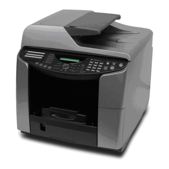
Here is a brief description of how to use the keys on the operation panel. The operation panel below is for the J012. It has fewer keys than the J013 and J014 because it does not support the fax function. -
Page 50: Summary Of Important Operation Panel Keys
Text and Photo. Both LEDs on. Allows the machine to set automatically the optimum settings for an original that contains both text and photos. Data-in Flashes while the machine is receiving a print job. Lights and J012/J013/J014 CÓPIA NÃO CONTROLADA... - Page 51 2-Sided Original / Pressing this key toggles the settings. The LED shows which 2-Sided Copy function is selected. 2-Sided Original. Enables scanning of double-sided originals 2-Sided Copy. Duplex prints an original with pages printed on one side. J012/J013/J014 CÓPIA NÃO CONTROLADA...
-
Page 52: Entering Text
To delete a number move [ ] or [ ] the cursor to the number to delete then press [No]. This deletes the number at the cursor position. To enter a plus sign (+), minus sign (-), ampersand (&), or slash (/) press [#] then [ ] to J012/J013/J014 CÓPIA NÃO CONTROLADA... - Page 53 [ ] or [ ] the letter to enter then press the same number key again. To delete a letter, move the cursor [ ] or [ ] to the letter to delete then press [No]. This deletes the letter at the cursor position. J012/J013/J014 CÓPIA NÃO CONTROLADA...
-
Page 54: Quick Summary Of Important Procedures
Section 4 “Troubleshooting.” To clean the print heads Before cleaning the print heads always do a Nozzle Check to determine which color is not printing. The print heads should be cleaned only if a problem exists. J012/J013/J014 1-10 CÓPIA NÃO CONTROLADA... -
Page 55: To Flush The Print Heads
"*Please Wait*" displays until flushing is finished. Do not start any other operation until cleaning stops. [Clear Modes] Print head cleaning and flushing both consume ink, but flushing consumes more ink than cleaning. Flush the print head nozzles only if three cleanings do not solve the problem. 1-11 J012/J013/J014 CÓPIA NÃO CONTROLADA... -
Page 56: To Feed 1 Blank Sheet (Paper Feed Test)
[Menu]> "System Settings?" [ ] or [ ] > "Maintenance?" > [Yes]> "1 Nozzle Check?" [ ] or [ ] > "8 De-condensation?" > [Yes]. Three blank sheets of paper feed. [Clear Modes] > Standby J012/J013/J014 1-12 CÓPIA NÃO CONTROLADA... -
Page 57: Installation Procedure
CD-ROM (Printer Driver, HTML Manual) CD-ROM (Printer Driver, HTML Manual) EU languages Quick Installation Procedure (English) Quick Installation Procedure (10 Languages) Safety Information (English) Safety Information (10 languages) Warranty Statement User Registration Card Help Desk Guide Energy Star Sticker 1-13 J012/J013/J014 CÓPIA NÃO CONTROLADA... -
Page 58: Remove The Shipping Material
Before you do any of the procedures in this manual, make sure the printer is turned off and unplugged from the power source. Do not turn the printer on until you instructed to do so. Remove the protective covering. Remove the plastic bag. J012/J013/J014 1-14 CÓPIA NÃO CONTROLADA... -
Page 59: Carrying The Printer
Lift the machine by the grooves on both sides as shown. Be sure to use two people when lifting the machine. Machine Weight Machine Weight J012 20 kg (44 lb.) J013 23 kg (50.7 lb.) J014 23.5 kg (51.8 lb.) Move the machine to the location where you want to install it. - Page 60 CÓPIA NÃO CONTROLADA Installation Procedure Remove all of the orange shipping tape from the machine body. [1] Front [2] Inside ADF. [3] Under platen/scanner unit [4] Under open scanner unit [5] Back of machine (remove power cord) J012/J013/J014 1-16 CÓPIA NÃO CONTROLADA...
- Page 61 Push the shipping lock up to the unlock position. Make sure the lock is fully in the unlock position or the scanner will not move and the machine will display an error code. Lower the scanner unit. 1-17 J012/J013/J014 CÓPIA NÃO CONTROLADA...
-
Page 62: Install The Print Cartridges
Make sure an additional set of print cartridges (purchased separately) is available. Use only Ricoh Print Cartridges designed for use with this printer. Open the right front cover. Remove the Black Print cartridge from its package. J012/J013/J014 1-18 CÓPIA NÃO CONTROLADA... - Page 63 Install the other print cartridges in the same way. Make sure that the four cartridges are inserted in this order, from left to right: K (Black), C (Cyan), M (Magenta), Y (Yellow) Close the right front cover. 1-19 J012/J013/J014 CÓPIA NÃO CONTROLADA...
-
Page 64: Load Paper
Raise the output tray. Pull the paper tray out of the machine. Squeeze to release the paper guides then slide the guides to a position slightly wider than the paper. Fan the stack to remove static cling. J012/J013/J014 1-20 CÓPIA NÃO CONTROLADA... - Page 65 The width side fences and bottom fence should not be too tight against the sides and bottom of the stack. If the stack bows upward, the fences are too tight. Adjust the side fence positions so the top of the stack is perfectly flat. 1-21 J012/J013/J014 CÓPIA NÃO CONTROLADA...
- Page 66 CÓPIA NÃO CONTROLADA Installation Procedure Push the tray slowly into the printer until it stops. 10. Lower the output tray. J012/J013/J014 1-22 CÓPIA NÃO CONTROLADA...
-
Page 67: Connect The Power Cord
If you accidentally turn the printer off while the ink tanks are filling, or if there is a power failure the printer will dump the ink and empty the tanks. The next time the printer is turned on, it will display the ‘ink out’ alert. 1-23 J012/J013/J014 CÓPIA NÃO CONTROLADA... -
Page 68: Select Country And Language
[ ] or [ ] > Select the size of paper that will be loaded in Tray 1 [Yes]> "Tray Paper Setting?" [Clear Modes> Standby 10. Cycle the machine off/on. Do a Nozzle Check [Menu]> "System Settings?" J012/J013/J014 1-24 CÓPIA NÃO CONTROLADA... -
Page 69: Print A System Summary
Make sure that both USB cable plugs are firmly inserted. Install the Printer Driver The following items are also installed during installation of the printer driver: TWAIN Driver (scanner) LAN-Fax driver (network and fax operation) Device Setting utility 1-25 J012/J013/J014 CÓPIA NÃO CONTROLADA... -
Page 70: Installation Notes
"Hardware Installation" dialog box opens, just click [Yes] or [Continue Anyway] to continue with the installation. If the "Found New Hardware" dialog box opens: Click [Install from a list or specific location…] then click [Next]. Click [Include this location in the search] then click [Browse]. J012/J013/J014 1-26 CÓPIA NÃO CONTROLADA... - Page 71 CD-ROM icon and then double-click "Setup.exe" to start the installation. The User Guide icon appears on the desktop immediately after the installation is finished. If you are prompted to restart the computer, restart the computer immediately. 1-27 J012/J013/J014 CÓPIA NÃO CONTROLADA...
-
Page 72: Options
CÓPIA NÃO CONTROLADA Options 1.4 OPTIONS Three options are available for the J012/J013/J014 Series machines. Option J012 J013 J014 J507 Multi Bypass Tray J509 Paper Feed Unit J510 Std* Standard (no installation required) 1.4.1 PAPER FEED UNIT Install the Paper Feed Unit The paper feed unit must be prepared and set up before the machine is placed on top of the unit. -
Page 73: Load Paper In The Paper Feed Unit
Add paper until it as far as the load limit marks. To prevent paper jams, never load paper higher than the load limit mark. Pinch the tabs of the bottom fence. Then move it to the edge of the stack. 1-29 J012/J013/J014 CÓPIA NÃO CONTROLADA... -
Page 74: Do The Paper Type/Size Settings For Tray 2
1.4.2 MULTI BYPASS TRAY J507 The multi-bypass tray is an option that can be installed on any J012, J013, or J014 machine. Installing the Multi Bypass Tray Make sure that the machine is switched off and disconnected from its power source. -
Page 75: Set Paper Type And Size For The Multi Bypass Tray
12. Cycle the machine off/on. 1.4.3 NETWORK INTERFACE BOARD J510 The Network Interface Board J510 is an option for the J012 and J013 machines only. The network board is built into the J014. Install the NIB Check the type of machine to be installed: The network interface board is built into the J014, so the installation procedure described below is not necessary for the J014. -
Page 76: Connect The Nib
For more about how to connect the Ethernet cable and perform the network settings, see the "Quick Installation Guide.” Connect the NIB Be sure to install the necessary network equipment (a hub, for example) before connecting the Ethernet cable to the machine. J012/J013/J014 1-32 CÓPIA NÃO CONTROLADA... -
Page 77: Do The Network Settings
Before doing this procedure ask the network administrator for the IP address. If the machine is off, press [Power] to switch it on. [Menu] > "System Settings?" [ ] or [ ] > "Network Settings" > [Yes]. These are the settings on the Network Settings menu. 1-33 J012/J013/J014 CÓPIA NÃO CONTROLADA... - Page 78 Do the settings for "2. Subnet Mask" and "3. Gateway Address.” Do the settings for "4. DNS Settings" and "5. Transfer Speed" if these settings are required. Please Re-start Power Off On [Power]> Cycle the machine off/on to save the settings. J012/J013/J014 1-34 CÓPIA NÃO CONTROLADA...
-
Page 79: Important Information
Never disconnect the power cord without first turning off the machine. To lift the machine, grip it at the center of each side by the hand recesses provided. Machine Weight J012 20 kg (44 lb.) J013 23 kg (50.7 lb.) J014 23.5 kg (51.8 lb.) -
Page 80: If The Machine Is Not Used Frequently
If the Nozzle Check print is still not satisfactory, allow the printer to sit idle for at least 8 hours and then print another Nozzle Check. 1.5.3 MOVING THE PRINTER Switch the printer off. Disconnect all cables (USB, Ethernet, power cord). Pull the scanner release lever and raise the scanner unit. J012/J013/J014 1-36 CÓPIA NÃO CONTROLADA... - Page 81 Carry it slowly and avoid tilting the machine. If the machine is being moved a long distance, pack it in its original box. Be sure to unlock the shipping lock after the machine arrives at its new location. 1-37 J012/J013/J014 CÓPIA NÃO CONTROLADA...
- Page 82 CÓPIA NÃO CONTROLADA CÓPIA NÃO CONTROLADA...
-
Page 83: Preventive Maintenance
CÓPIA NÃO CONTROLADA PREVENTIVE MAINTENANCE SECTION 2 PREVENTIVE MAINTENANCE REVISION HISTORY Page Date Added/Updated/New None CÓPIA NÃO CONTROLADA... -
Page 84: Pm Table
For more, see "Image Adjustment" in section "3. Replacement and Adjustment.” Transport Belt Damp cloth. Then dry cloth. Important: To protect the surface of the transport belt, never use alcohol or any other type of organic solvent. J012/J013/J014 CÓPIA NÃO CONTROLADA... -
Page 85: Regular Cleaning
CÓPIA NÃO CONTROLADA PM Table 2.1.2 REGULAR CLEANING The following items should be cleaned regularly: Exposure glass Scanning glass White plate Note: Avoid bending the exposed edges of the mylars. Platen background plate J012/J013/J014 CÓPIA NÃO CONTROLADA... - Page 86 CÓPIA NÃO CONTROLADA CÓPIA NÃO CONTROLADA...
-
Page 87: Replacement And Adjustment
CÓPIA NÃO CONTROLADA REPLACEMENT AND ADJUSTMENT SECTION 3 REPLACEMENT AND ADJUSTMENT REVISION HISTORY Page Date Added/Updated/New 40 ~ 44 09/09/2009 Controller replacement procedure CÓPIA NÃO CONTROLADA... - Page 88 CÓPIA NÃO CONTROLADA CÓPIA NÃO CONTROLADA...
-
Page 89: Before Replacing Parts
Ink Collector Unit Ink Tank Cover Key Switch Panel Operation Panel NIB Cover Protects inserted NIB Operation Panel Fax Seal Original Cover Paper Cassette Standard Paper Cassette (PFU) Option Paper Output Tray On top of paper cassette J012/J013/J014 CÓPIA NÃO CONTROLADA... - Page 90 Easy ARDF Unit Easy ARDF Unit (J013/J014) Easy Air Release Solenoid Easy Carriage Position Sensor Easy Carriage Unit Easy Controller Board (J012) Easy Controller Board (J013) Easy Controller Board (J014) Easy Cooling Fan Difficult Cover: Rear Easy J012/J013/J014 CÓPIA NÃO CONTROLADA...
- Page 91 Easy Horizontal Motor Difficult Maintenance Unit Easy NCU (EU) Easy NCU ( NA) Easy Easy Scanner Unit (J012 EU) Difficult Scanner Unit (J012 NA) Difficult Scanner Unit (J013 EU) Difficult Scanner Unit (J013 NA) Difficult Scanner Unit (J014 EU) Difficult...
- Page 92 Removal of all covers and the scanner unit and back cover are required. Level 3: Require precision adjustment at factory (Not Replace in the field) Component Comments Carriage Unit Ink Supply Pump Unit Transport Belt Charge Roller Temperature/Humidity Sensor Paper End Sensor Paper Feed Roller J012/J013/J014 CÓPIA NÃO CONTROLADA...
-
Page 93: Important Notice
During parts removal never remove any of the screws shown below. These screws fasten the carriage brackets that keep the carriage unit correctly aligned. If these screws are loosened or removed, this could throw the carriage mechanism out of alignment. J012/J013/J014 CÓPIA NÃO CONTROLADA... -
Page 94: Procedure Summary
Cassette, Output Tray, 4) Right Cover Cleaning – Feed Roller 1) Platen or ADF., 2) Scanner to Full Upright, 3) Paper Cassette, Output Tray Cleaning – Flushing Gate 1) Platen or ADF., 2) Scanner to Full Upright Cleaning – Friction Pad J012/J013/J014 CÓPIA NÃO CONTROLADA... - Page 95 Scanner Unit, 4) Left Cover, 5) Right Cover, 6) Rear Cover Horizontal Motor 1) Platen or ADF., 2) Scanner to Full Upright, 3)Paper Cassette, Output Tray, 4) Right Cover, 5) Left Cover, 6) Scanner Unit, 7) Rear Cover J012/J013/J014 CÓPIA NÃO CONTROLADA...
- Page 96 1) Platen or ADF., 2) Scanner to Full Upright, 3) Paper Cassette, Output Tray, 4) Left Cover Paper Cassette, Output Tray Platen (J012) Engine Unit Swap 1) Platen or ADF., 2) Scanner to Full Upright, 3) Paper Cassette, Output Tray, 4) Right Cover, 5) Left Cover, 6)
- Page 97 1) Platen or ADF., 2) Scanner to Full Upright, 3) Paper Cassette, Output Tray, 4) Left Cover Vertical Motor 1) Platen or ADF., 2) Scanner to Full Upright, 3) Paper Cassette, Output Tray, 4) Left Cover J012/J013/J014 CÓPIA NÃO CONTROLADA...
-
Page 98: Common Procedures
Common Procedures 3.2 COMMON PROCEDURES 3.2.1 NETWORK INTERFACE BOARD (NIB) This procedure applies to the J012/J013 only. The NIB is built into the J014. Press down on the tab release [1]. Pull the NIB out of the machine. 3.2.2 DUPLEX UNIT Raise the left and right release tabs [1] and [2] together to unlock the duplex unit. -
Page 99: Ink Collector Unit
When you dispose of the used ink collector unit always obey the local laws and regulations regarding the disposal of such items. Never attempt to clean and re-use an ink collector unit. To remove the ink collector unit: 3-11 J012/J013/J014 CÓPIA NÃO CONTROLADA... - Page 100 Discard the used ink collector tank. Obey the local laws and regulations regarding disposal of items such as the full ink collector tank. Never attempt to clean a full ink collector tank and use it again. J012/J013/J014 3-12 CÓPIA NÃO CONTROLADA...
-
Page 101: Platen (J012 Only)
CÓPIA NÃO CONTROLADA Common Procedures 3.2.4 PLATEN (J012 ONLY) This procedure applies to the J012 only. Raise the platen. Pull the platen straight up to remove it. 3-13 J012/J013/J014 CÓPIA NÃO CONTROLADA... -
Page 102: Adf. (J013/J014)
Loosen the knob screws (x2) of the ADF. connector [1] and disconnect it. Raise the ADF. [2] while tilting it slightly toward the back of the machine to disengage the feet of the ADF. Raise the feet out of the holes and remove the ADF. J012/J013/J014 3-14 CÓPIA NÃO CONTROLADA... -
Page 103: Original Pressure Plate
While holding the plate at about a 30 degree angle, set the left tabs [1] in the holes. Lower the original pressure plate and set center tabs [2]. Use a flat-head screwdriver to set right tabs [3]. 3-15 J012/J013/J014 CÓPIA NÃO CONTROLADA... -
Page 104: Scanner To Full Upright
Preparation The scanner unit must be raised to the full upright position to remove the left and right covers. Remove platen (J012 3.2.4) or ADF. (J013/J014 3.2.5). Pull forward the release lever under the operation panel [1] and raise the scanner unit. -
Page 105: Paper Cassette, Output Tray
Lower the paper output tray. Use the middle fingers of both hands to press the output tray arms [3] and [4] inward to release them, then pull the output tray out of the machine. 3.2.9 RIGHT FRONT COVER 3-17 J012/J013/J014 CÓPIA NÃO CONTROLADA... -
Page 106: Right Cover
CÓPIA NÃO CONTROLADA Common Procedures Pull on the latch [1] and lower the right front cover. Disengage left arm [2] of the cover from its hole and remove the cover. 3.2.10 RIGHT COVER J012/J013/J014 3-18 CÓPIA NÃO CONTROLADA... -
Page 107: Right Inner Cover
Remove: (1) paper cassette, (2) paper output tray, (3) right front cover, (4) right cover Remove screws [1] and [2] then remove the hinge. Remove screw [3]. Loosen screw [4] (do not remove it). On the right side of the machine remove screw [5]. 3-19 J012/J013/J014 CÓPIA NÃO CONTROLADA... - Page 108 10. Under the right front corner of the inner cover [1] remove the screws ( x2). 11. Separate the corner of the inner cover [2] from the top cover [3]. 12. Slide the right inner cover forward to remove it. J012/J013/J014 3-20 CÓPIA NÃO CONTROLADA...
-
Page 109: Left Cover
Use the tip of a small flat-head screwdriver to press and release tabs [1] and [2] at the front and tab [3] at the top rear corner. Carefully remove the left cover to prevent damaging the other tabs on the top and bottom edges of the cover. 3.2.13 FRONT COVER 3-21 J012/J013/J014 CÓPIA NÃO CONTROLADA... - Page 110 Never attempt to remove the front cover without first disconnecting the connector. This is the harness connector of the scanner unit detection sensor attached under the top of the top cover. This sensor detects the opening and closing of the scanner unit. J012/J013/J014 3-22 CÓPIA NÃO CONTROLADA...
-
Page 111: Scanner Unit
Printer in standby mode? Use the Web Browser to print a list of all the settings in the address book. Start the Device Setup Utility. Click the "Connect to Device" icon. In the menu bar click [Tools]> [Download]. 3-23 J012/J013/J014 CÓPIA NÃO CONTROLADA... - Page 112 On the left click "Quick Dial List", "Speed Dial List", or "Group List" to display the address book information on the right. The downloaded data is in the computer memory and must be saved to a file. From the "File" menu select "Save As.” The "Save As" screen opens. J012/J013/J014 3-24 CÓPIA NÃO CONTROLADA...
- Page 113 At the left front corner of the machine, disconnect the scanner power cable harness[1] CN4 from the PSU ( x1). Pull the harness out from behind the four L-clamps. At the left rear corner of the machine, release the harness [2] from the white harness clamps ( x3). 3-25 J012/J013/J014 CÓPIA NÃO CONTROLADA...
- Page 114 Pull out the USB connector [2]. If screw [1] is loose, tighten it. While supporting the upright scanner unit with one hand to prevent it from falling back, raise the latch [2] to disconnect the support strap. J012/J013/J014 3-26 CÓPIA NÃO CONTROLADA...
- Page 115 Click the [Yes] button to start the uploading the address book data from the file to the machine. While the data is uploading to the machine, you will see "*Please Wait* Setting from PC…" displayed on the printer operation panel. 3-27 J012/J013/J014 CÓPIA NÃO CONTROLADA...
-
Page 116: Rear Cover
Position on a table so its rear edge overhangs the edge of the table so you can see the tab locks. To prevent ink spillage from the print head tanks, do not turn the machine on its side or on its front edge. J012/J013/J014 3-28 CÓPIA NÃO CONTROLADA... - Page 117 While pulling the back cover away from the machine, use the tip of a small flat-head screwdriver [1] to gently disengage first the right tab and then the left tab. After the tabs have been released pull the back cover away from the machine. 3-29 J012/J013/J014 CÓPIA NÃO CONTROLADA...
-
Page 118: Flushing Unit
Remove: (1) left cover ( 3.2.12) Remove screw [1] ( x1). Lift the hook [2] behind the vertical encoder wheel. Never touch the surface vertical encoder wheel around its edges. Lift the flushing unit [3] out of the machine. J012/J013/J014 3-30 CÓPIA NÃO CONTROLADA... -
Page 119: Maintenance Unit
Always push the envelope selector to the rear before you move the carriage manually. Push the carriage [4] to the left side of the machine. 3-31 J012/J013/J014 CÓPIA NÃO CONTROLADA... - Page 120 Do not touch the bottom of the unit. Remove screws [5] and [6], to disconnect the maintenance unit motor from the maintenance unit ( x2) Set the maintenance unit [7] on a cloth or sheet of paper. J012/J013/J014 3-32 CÓPIA NÃO CONTROLADA...
-
Page 121: Encoders
Remove screws [2], [3], [4], [5] on the side of the vertical stay ( x4). Remove the screw [6] on top of the vertical stay ( x1). Disconnect the spring [7] to release the tension on the timing belt. 3-33 J012/J013/J014 CÓPIA NÃO CONTROLADA... - Page 122 Insert the tip of a flathead screwdriver [9] between the frame and the hub of the wheel. Very slowly twist the screwdriver slightly to the left and right to free the wheel from the shaft. J012/J013/J014 3-34 CÓPIA NÃO CONTROLADA...
- Page 123 Insert the edge of the wheel into the gap of the vertical encoder sensor [3]. Push the wheel onto the shaft. Make sure that the wheel groove is locked onto the long pin. 3-35 J012/J013/J014 CÓPIA NÃO CONTROLADA...
-
Page 124: Horizontal Encoder Strip
Insert the tip of a plus (+) screwdriver into the hole at [C] and turn in counter-clockwise until the triangles [A] and [B] are aligned as shown on the right. Push the carriage unit [1] to the center of the machine. J012/J013/J014 3-36 CÓPIA NÃO CONTROLADA... - Page 125 First, on the right side of the machine attach the end of the strip with its beveled corner down as shown above. Next, attach the other end to the leaf spring on the left side of the machine. The machine will malfunction if the horizontal encode strip is installed incorrectly. 3-37 J012/J013/J014 CÓPIA NÃO CONTROLADA...
-
Page 126: Boards
Remove PSU board screws [2], [3], [4], [5] ( x4). A plastic corner cap is attached at [2]. Remove it from the machine if it falls off. Release the tab [6] then remove the PSU. J012/J013/J014 3-38 CÓPIA NÃO CONTROLADA... -
Page 127: Hvps
Remove: (1) paper tray, (2) paper output tray, (3) right cover, (4) front cover 3.2.8, 3.2.10, 3.2.13) Remove screw [1] ( x1). Remove cover screws [2] ( x4). Disconnect connectors [3] ( x2). Disengage the hooks [4] (x4) Disconnect the bayonet connector [5]. 3-39 J012/J013/J014 CÓPIA NÃO CONTROLADA... -
Page 128: Printer Engine Ctl Board, Nvram
Remove the control board [3] ( x12, FFC x2, x6). The NVRAM is on the bottom of the board. Turn the board over and lay it on a flat, clean surface so you can see the NVRAM [4]. J012/J013/J014 3-40 CÓPIA NÃO CONTROLADA... - Page 129 Attach the NVRAM so the curvature of the white line on the board matches the curvature of the indentation on the NVRAM chip. NOTE: The NVRAM can not be replaced with a new one, see Technical Service Bulletin J012/J013/J014 – 021 NVRAM CAN NOT BE REPLACED. 3-41 J012/J013/J014...
- Page 130 CÓPIA NÃO CONTROLADA Boards Rev. 09/09/2009 This page left intentionally blank. J012/J013/J014 3-42 CÓPIA NÃO CONTROLADA...
- Page 131 CÓPIA NÃO CONTROLADA Boards Rev. 09/09/2009 This page left intentionally blank. 3-43 J012/J013/J014 CÓPIA NÃO CONTROLADA...
-
Page 132: Duplex Unit Detection Board
Remove: (1) paper cassette, (2) paper output tray, (3) right cover, (4) left cover, (5) scanner unit, (6) rear cover ( 3.2.8, 3.2.10, 3.2.12, 3.2.7, 3.2.15) Remove screws [1], [2] ( x2). Disconnect the PCB [3] ( J012/J013/J014 3-44 CÓPIA NÃO CONTROLADA... -
Page 133: Motors
Gently (to avoid bending) push the leaf spring [1] to the right to release pressure on the horizontal encoder strip, then disconnect both ends of the strip and remove it. Remove screws [2] and [3]. At the rear corner of the printer, remove the horizontal motor [4] ( x1). 3-45 J012/J013/J014 CÓPIA NÃO CONTROLADA... - Page 134 CÓPIA NÃO CONTROLADA Motors Reassembly On the right side reattach the right notched end of the encoder strip first, with the beveled corner facing down. Attaching the film encoder strip incorrectly causes the machine to operate incorrectly. J012/J013/J014 3-46 CÓPIA NÃO CONTROLADA...
-
Page 135: Vertical Motor
Remove spring [2]. ( x1). Remove the motor screws [3], [4] ( x2). Remove the motor plate screws [5], [6] ( x2). Disconnect the timing belt [7]. Pull out the motor [8] and disconnect it ( x1). 3-47 J012/J013/J014 CÓPIA NÃO CONTROLADA... -
Page 136: Maintenance Unit Motor
This prevents damaging the print head unit when the carriage is moved manually. Always push the envelope selector to the rear before you move the carriage manually. Push the carriage [4] to the left side of the machine. J012/J013/J014 3-48 CÓPIA NÃO CONTROLADA... - Page 137 13. Remove screws [5] and [6], to disconnect the maintenance unit motor [7] from the maintenance unit ( x2) 14. Set the maintenance unit on a cloth or sheet of paper. 3-49 J012/J013/J014 CÓPIA NÃO CONTROLADA...
-
Page 138: Rear Fan
Remove: (1) paper cassette, (2) paper output tray, (3) right cover, (4) left cover, (5) scanner unit, (6) rear cover ( 3.2.8, 3.2.10, 3.2.12, 3.2.14, 3.2.15) 17. Disconnect the fan harness [1] ( x1). 18. Remove screws [2], [3] ( x2). 19. Remove the cooling fan. J012/J013/J014 3-50 CÓPIA NÃO CONTROLADA... -
Page 139: Front Fan
Remove: (1) paper cassette, (2) paper output tray, (3) right front cover, (4) right cover. 3.2.8, 3.2.9, 3.2.10) Pull the fan connector harness [1] out of its L-clamp. Disconnect the fan harness connector [2] ( x1). Remove fan bracket screws [3] and [4] then remove the fan ( x2). 3-51 J012/J013/J014 CÓPIA NÃO CONTROLADA... -
Page 140: Sensors
Release the scanner unit power harness [1] ( x1). Remove screws [2], [3], [4], [5] on the side of the vertical stay ( x4). Remove the screw [6] on top of the vertical stay ( x1). Remove screws [7], [8] ( x2). J012/J013/J014 3-52 CÓPIA NÃO CONTROLADA... -
Page 141: Carriage Position Sensor
Remove: (1) paper cassette, (2) paper output tray, (3) right cover ( 3.2.8, 3.2.10) Move the envelope selector [1] forward. Remove the sensor from under the air release solenoid bracket (Hooks x3) Disconnect the sensor [2] ( 3-53 J012/J013/J014 CÓPIA NÃO CONTROLADA... -
Page 142: Ink Level Sensor
Remove the air release solenoid screws [3], [4] ( x2). Remove the air release solenoid [5]. Disconnect the sensor from the bracket frame ( x1). Release the sensor tabs [6]. Pull out the sensor [7] and disconnect it. J012/J013/J014 3-54 CÓPIA NÃO CONTROLADA... -
Page 143: 1St Registration Sensor
Use the tip of your finger or a small screwdriver to separate the tab from its hole on the side of the cover [2], then lift the cover off. Pull the connector off of the 1st registration sensor [3]. Remove the 1st registration sensor [4]. 3-55 J012/J013/J014 CÓPIA NÃO CONTROLADA... -
Page 144: 2Nd Registration Sensor
[2]. Push the carriage [3] to the right side of the machine. Remove the dislodged sensor cover [4]. Remove the sensor [5]. Pull out the sensor [6] and disconnect it ( x1). J012/J013/J014 3-56 CÓPIA NÃO CONTROLADA... - Page 145 The cover cannot pass below the steel shaft. With its front edge down, lower the cover between shaft and the timing belt. Slowly move the carriage [3] left and right to confirm that the carriage does not hit the sensor cover. 3-57 J012/J013/J014 CÓPIA NÃO CONTROLADA...
-
Page 146: Scanner Unit Sensor
Push the scanner unit sensor [2] to the right to slide it off its pegs (x2). Reassembly Make sure the sensor is mounted on both pegs before you try to reattach the cover. The cover will not fit over the sensor until the sensor is set correctly on both pegs. J012/J013/J014 3-58 CÓPIA NÃO CONTROLADA... -
Page 147: Air Release Solenoid
Remove: (1) paper cassette, (2) paper output tray, (3) right cover ( 3.2.8, 3.2.10) Remove the bracket screws [1], [2] ( x2) Remove the air release solenoid screws [3], [4] ( x2). Remove the air release solenoid [5] ( x1). 3-59 J012/J013/J014 CÓPIA NÃO CONTROLADA... -
Page 148: Cleaning Procedures
Maintenance unit Wet cloth (use water). Always use a tightly wrapped dry cloth to remove the ink that has hardened around the suction cap and wiper blade when you replace the ink collector tank. J012/J013/J014 3-60 CÓPIA NÃO CONTROLADA... -
Page 149: Flushing Gate Cleaning
The damp cloth prevents scratching the suction cup. A scratched suction cup could cause poor print quality. Never use tissue, cotton, or any other type of material to wrap the tip of the screwdriver. Such material can contaminate the maintenance unit with loose fibers. 3-61 J012/J013/J014 CÓPIA NÃO CONTROLADA... - Page 150 Damaging the fragile lip of the suction cap [2[. Do not insert the tip of the screwdriver down into either the right air vent or suction cap. Close the scanner unit. Press the power button to switch the printer on. J012/J013/J014 3-62 CÓPIA NÃO CONTROLADA...
-
Page 151: Feed Roller Cleaning
Push the transport roller gear [3] to the left. This unlocks the roller and allows it to rotate freely. Rotate the roller and clean it with a dry cloth. Be sure to lock the roller in place after cleaning. 3-63 J012/J013/J014 CÓPIA NÃO CONTROLADA... -
Page 152: Transport Belt Cleaning
Repeat Steps 3 and 4 until the entire surface of the belt is clean. Make sure that the entire surface of the belt is completely dry. Water on the surface of the transport belt could interfere with the operation of the printer. J012/J013/J014 3-64 CÓPIA NÃO CONTROLADA... -
Page 153: Friction Pad Cleaning
(The white line shows the position of the friction pad under the machine. Under the machine remove the screw [1] and remove the friction pad. Use a damp cloth to clean the surface of the friction pad [2]. 3-65 J012/J013/J014 CÓPIA NÃO CONTROLADA... -
Page 154: Horizontal Encoder Strip Cleaning
Move the carriage to the left. [Menu]> > "Maintenance"> [Yes}> "1 Nozzle Check?" > "9 Move Print Heads?"> [Yes]> "Please Wait" After a few seconds the carriage will move the left and the printer will go off. J012/J013/J014 3-66 CÓPIA NÃO CONTROLADA... - Page 155 10. Do "Print Head Flushing" if the pattern is not satisfactory, even after three print head cleanings. 11. Do "Print-Head Flushing" and print another Nozzle Check Pattern. 12. If the Nozzle Check Pattern is still not satisfactory after flushing the print heads, replace the horizontal encoder strip. 3-67 J012/J013/J014 CÓPIA NÃO CONTROLADA...
-
Page 156: Swapping The Engine Unit
The engine unit includes the main engine components and does not include the: ADF. Unit Scanner unit Main CTL board in the scanner unit To swap the engine unit: Remove the ADF. ( 3.2.5) Remove the scanner unit ( 3.2.14) Replace the engine unit. J012/J013/J014 3-68 CÓPIA NÃO CONTROLADA... -
Page 157: Firmware Update
During the Update Procedure While the update procedure is in progress: Never switch off the printer Never disconnect the USB cable Do not start any print job or run an application that uses the printer driver, Status Monitor, 3-69 J012/J013/J014 CÓPIA NÃO CONTROLADA... -
Page 158: Before You Begin
The following procedure uses Windows XP screenshots. Update Procedure Double-click [GelSprinterGX3000SF_Setup.bat] to start the update. Select [English], and then click [OK]. Check the displayed details, and then click [Next >]. Select the printer name, and then click [Next >]. J012/J013/J014 3-70 CÓPIA NÃO CONTROLADA... - Page 159 [Printer], and then click [Next >]. Once the firmware has been updated, you cannot restore to the previous version. Click [OK] to start the update. Switch the printer off , wait a few seconds, and then turn it back on. 3-71 J012/J013/J014 CÓPIA NÃO CONTROLADA...
- Page 160 "The Ethernet board is not installed." If this message appears, press [OK] to cancel the Ethernet board firmware update. The Master Controller Firmware Update Wizard starts. Go to Step 14. Click [Next >] J012/J013/J014 3-72 CÓPIA NÃO CONTROLADA...
- Page 161 Check that the system version for [Update Data] is newer than the system version for [Ethernet Board], and then click [Next >]. Once the firmware has been updated, you cannot restore it to the previous version. Click [OK] to start the update. 3-73 J012/J013/J014 CÓPIA NÃO CONTROLADA...
- Page 162 Check the version, and then click [Finish] to start the master controller firmware update. Click [Next >] Check that the system version for [Update Data] is newer than the system version for [Master Controller], and then click [Finish]. J012/J013/J014 3-74 CÓPIA NÃO CONTROLADA...
- Page 163 CÓPIA NÃO CONTROLADA Firmware Update Click [OK] to start the update. Switch the printer off, wait a few seconds, and then turn it back on. Check the version, and then click [Finish]. The update is complete. 3-75 J012/J013/J014 CÓPIA NÃO CONTROLADA...
- Page 164 CÓPIA NÃO CONTROLADA CÓPIA NÃO CONTROLADA...
-
Page 165: Troubleshooting
CÓPIA NÃO CONTROLADA TROUBLESHOOTING SECTION 4 TROUBLESHOOTING REVISION HISTORY Page Date Added/Updated/New 04/20/2009 SC940 35 ~ 36 01/02/2008 Jam 14, Jam 15 CÓPIA NÃO CONTROLADA... - Page 166 CÓPIA NÃO CONTROLADA CÓPIA NÃO CONTROLADA...
-
Page 167: Display Summary
The 0% display is the cartridge near end alert. Printing is still possible until the ink in the print head is gone. The arrow display on the far right is the print cartridge end alert. The machine cannot be used until the print cartridge has been replaced. J012/J013/J014 CÓPIA NÃO CONTROLADA... -
Page 168: Display Menu Summary
Note: The machine will require some time to recover after it receives a print job while in the energy saver mode. The machine might not enter the energy save mode while an error message is displayed. J012/J013/J014 CÓPIA NÃO CONTROLADA... - Page 169 ARDF. Alert. Adjusts the volume of the beep that sounds when a transmission error or other error occurs. Line Vol. Adjusts the volume of the speaker used during on-hook mode with the fax. J012/J013/J014 CÓPIA NÃO CONTROLADA...
- Page 170 Note: The "Tray2" and "Bypass" items do not appear until after these options have been installed. 2 Tray2? Paper Type?. Selects the paper type for Tray 1 (Standard), the Tray 2 (option), and Multi Bypass Tray (option). Default: Plain J012/J013/J014 CÓPIA NÃO CONTROLADA...
- Page 171 For example, if paper runs out while feeding from Tray 1, the machine will automatically select Tray 2 and continue the job without interruption. Default: On. J012/J013/J014 CÓPIA NÃO CONTROLADA...
- Page 172 Network Settings? Use to do the network settings. The network settings appear only after the NIB has been installed. (The NIB is standard on the J014, an option for the J012/J013.) 1 Machn. IP Address? Auto. Get IP address from DHCP server.
- Page 173 (text is not affected). This is a new feature Once Level Color Mode is selected, the amount of ink used to print images and graphics is reduced by almost 50%, the text remains at the same density of the normal color mode. J012/J013/J014 CÓPIA NÃO CONTROLADA...
- Page 174 Off: The job does not print if the specified paper size/type is not loaded in the tray. The job will execute once the specified paper size/type is loaded. On: The job prints even if the specified paper size/type is not loaded in the tray. J012/J013/J014 CÓPIA NÃO CONTROLADA...
- Page 175 Resets the counter for the ink collector unit after the old unit is replaced with a new one. Note: If this item is executed and the ink collector unit does not require replacement, then this message appears: "Unit replacement is not required. Press Yes Key.” J012/J013/J014 CÓPIA NÃO CONTROLADA...
- Page 176 PCL Menu? For more details, please refer to the User's Guide. Note: These settings are displayed for the J014 only. The J012/J013 do not support PCL. The settings take effect during PCL print jobs only. J012/J013/J014 4-10 CÓPIA NÃO CONTROLADA...
- Page 177 Adjusts the paper feed setting if the Nozzle Check test pattern shows horizontal misalignment, or if printed images appear uneven. 6 Registration? Adjusts the print starting point for each paper tray. The starting point is defined in the upper left corner. 4-11 J012/J013/J014 CÓPIA NÃO CONTROLADA...
- Page 178 9 Move Prnt-Heads? Moves the print head unit to the right side of the machine to make it easier to remove a paper jam. 10 Reset Counter Resets the ADF. counter. J012/J013/J014 4-12 CÓPIA NÃO CONTROLADA...
-
Page 179: Status Reports
Machine ID 2. System Summary Page Count 1. Page Counter Paper Tray Information 2. System Summary SC Codes (Most Recent) 2. System Summary SP Code List 3. Engine Summary Chart Service Data 4. Service Data List 4-13 J012/J013/J014 CÓPIA NÃO CONTROLADA... -
Page 180: Page Counter
[ ] or [ ] > "Counter?" > [Yes] [ ] or [ ] > "Print Counter?" > [Yes] A printed single-sided sheet counts as "1.” A printed double-sided sheet counts as "2.” The counter limit is 99,999. J012/J013/J014 4-14 CÓPIA NÃO CONTROLADA... -
Page 181: System Summary (Config. List)
[ ] or [ ] > "Service Summary" > [Yes] > "Press Yes Key" > [Yes] [No] > [ ] or [ ] > "End" > [Yes] > Machine switches off. [Power] to switch the machine on. 4-15 J012/J013/J014 CÓPIA NÃO CONTROLADA... -
Page 182: Engine Summary Chart
To enter the SP mode: [Clear Modes]> [1] [0] [7]> [Clear/Stop] for 3 sec. SYSTEM Ver.0.51 Service Menu ] > "Engine Maint." SP No. 1000 [ ] x 4 times> "5000"> [Yes] [ ] twice> "5200"> [Yes] x 3 times PRINT SMC 5200 J012/J013/J014 4-16 CÓPIA NÃO CONTROLADA... - Page 183 MODEL Number of the Printer Model SER_NO Printer Serial Number Firm Ver Version number of the firmware in the printer SENSOR1, SENSOR2 Sensor information SP No, Name, Value SP number, name, value of current setting 4-17 J012/J013/J014 CÓPIA NÃO CONTROLADA...
-
Page 184: Service Data List
[ ] or [ ] > "4. REPORT"> [Yes]> "SERVICE DATA LIST"> [Yes] 4.2.5 5. T.30 PROTOCOL LIST [Menu]> [#]> [*]> [Yes]> "1. SERVICE'S CHOICE" [ ] or [ ] > "4. REPORT"> [Yes]> "SERVICE DATA LIST" [ ] or [ ] > "T.30 PROTOCOL LIST"> [Yes] J012/J013/J014 4-18 CÓPIA NÃO CONTROLADA... -
Page 185: Self-Diagnostic Test Flow
CÓPIA NÃO CONTROLADA Self-Diagnostic Test Flow 4.3 SELF-DIAGNOSTIC TEST FLOW 4-19 J012/J013/J014 CÓPIA NÃO CONTROLADA... - Page 186 CÓPIA NÃO CONTROLADA Self-Diagnostic Test Flow J012/J013/J014 4-20 CÓPIA NÃO CONTROLADA...
-
Page 187: Sc Error Codes
The printer can continue to print, but if the Ink near end. problem is not corrected soon the printer will no Ink collector unit near full. longer be able to operate. The operator must correct the problem as soon as possible. 4-21 J012/J013/J014 CÓPIA NÃO CONTROLADA... -
Page 188: Out-Of-Range Temperature Errors
Let one hour pass for the printer to adjust to room temperature before you use it after moving to a new location. This is very important after the printer is moved from a cold location into a warm room. J012/J013/J014 4-22 CÓPIA NÃO CONTROLADA... -
Page 189: Sc Code Tables
Cycle the machine off/on read from the CCD. Exposure lamp defective CCD board defective (replace scanner unit) ⇒ Machine Stalls The machine has stalled. Cycle the power OFF/ON 4-23 J012/J013/J014 CÓPIA NÃO CONTROLADA... - Page 190 The ink sump on the left side of the Replace the ink sump. printer is full. Note: A software counter monitors the usage of the ink sump. There are no sensors associated with the ink sump. J012/J013/J014 4-24 CÓPIA NÃO CONTROLADA...
- Page 191 Protection During Transport At power on the printer Use only ink cartridges that are designed for use with this printer. detected that the ink in a cartridge is non-standard Never use re-filled ink cartridges. ink. 4-25 J012/J013/J014 CÓPIA NÃO CONTROLADA...
- Page 192 Never attempt to clean the old tank and reinstall it. Obey the local laws and guidelines regarding disposal of items such as the ink collector unit. J012/J013/J014 4-26 CÓPIA NÃO CONTROLADA...
- Page 193 When the carriage moved to Horizontal encoder sensor loose, the right, the carriage did broken, or defective. not stop at the HP. Or, the Horizontal encoder film broken, carriage scan check failed. disconnected, or installed upside down. HRB defective 4-27 J012/J013/J014 CÓPIA NÃO CONTROLADA...
-
Page 194: Jam Codes
Remove all the originals from the ADF. Open the ADF. and turn the dial to free the jammed original. Action Open the top cover of the ADF. and remove the jammed original or paper scraps. J012/J013/J014 4-28 CÓPIA NÃO CONTROLADA... -
Page 195: Paper Feed Jams
Cause: Feeler of relays sensor failed to return to its correct position Optional PFU (Tray 2) Problem Site CTL board Perform check, take action in this order: Action Inspect PFU for faulty parts and replace. 4-29 J012/J013/J014 CÓPIA NÃO CONTROLADA... - Page 196 Jammed paper or other obstruction in the paper path Trailing edge sensor feeler obstructed or damaged Problem Site Trailing edge sensor Perform check, take action in this order: Replace inverter guide plate. Action Replace trailing edge sensor. Replace CTL board. J012/J013/J014 4-30 CÓPIA NÃO CONTROLADA...
- Page 197 Obstruction or dirt on the transfer belt interfered with proper detection. Transfer belt unit Problem Site 1st Registration sensor 2nd Registration sensor Perform check, take action in this order: Clean the transfer belt. Action Replace 1st, 2nd Registration sensors. Replace Multi Bypass Tray. 4-31 J012/J013/J014 CÓPIA NÃO CONTROLADA...
- Page 198 Problem Site 2nd Registration sensor Perform check, take action in this order: Action Replace 2nd Registration sensor. Replace CTL board. Jam 9 Paper Jam from Tray 1 Between TE Sensor and Registration Sensors J012/J013/J014 4-32 CÓPIA NÃO CONTROLADA...
- Page 199 1st Registration sensor Problem Site 2nd Registration sensor CTL board Perform check, take action in this order: Replace the inverter guide plate. Action Replace the trailing edge sensor. Replace 1st, 2nd Registration sensors. Replace the CTL board. 4-33 J012/J013/J014 CÓPIA NÃO CONTROLADA...
- Page 200 1st Registration sensor Problem Site 2nd Registration sensor CTL board Perform check, take action in this order: Replace the inverter guide plate. Action Replace the trailing edge sensor. Replace 1st, 2nd Registration sensors. Replace the CTL board. J012/J013/J014 4-34 CÓPIA NÃO CONTROLADA...
- Page 201 The horizontal film encoder is dirty, slack, buckled, or damaged. Horizontal feed motor belt is loose or broken. Horizontal encoder film strip Problem Site Horizontal feed motor belt CTL board Action Perform check, take action in this order: 4-35 J012/J013/J014 CÓPIA NÃO CONTROLADA...
- Page 202 The registration sensor signals did not change. 1st Registration sensor Problem Site 2nd Registration sensor Perform check, take action in this order: Clean the transfer belt. Action Replace the 1st Registration sensor. Replace the 2nd Registration sensor. J012/J013/J014 4-36 CÓPIA NÃO CONTROLADA...
-
Page 203: Facsimile Errors
001E Timeout in V.17 ECM RX phase C 0x1F Machine cannot detect V.21 or V.8 signal with 35 sec. Cannot correct frame within 6 sec., a decoding line over 6 sec in non-ECM 0020 mode.. 4-37 J012/J013/J014 CÓPIA NÃO CONTROLADA... - Page 204 Line power over threshold for 60 sec. after MCF. No FSK or carrier signal 004A detected in ECM mode. 004B Correct FSK signal not detected even though FSK tone detected within 6 sec. 004C Handshake failed during re-training or between page during V34 RX. J012/J013/J014 4-38 CÓPIA NÃO CONTROLADA...
- Page 205 Modem disconnected in phase D after local machine sent flag sequence on 0062 control channel. 0063 No flag sequence on control channel within 6 sec. in phase D. No control channel signal received in phase D within 60 sec. even with power 0064 on the line. 4-39 J012/J013/J014 CÓPIA NÃO CONTROLADA...
-
Page 206: Communication (Tx)
Remote machine has no mailbox function or mailbox function is not 0089 compatible. 008B Local RX machine received DIS protocol but protocol not compatible. 008C Local machine memory insufficient for starting relay sending. 008D Received RX machine DIS protocol but remote machine could not receive J012/J013/J014 4-40 CÓPIA NÃO CONTROLADA... - Page 207 V.21 or JM signal not detected after CM signal was sent. 00B4 No Phase 2 signal detected within 25 sec. after CM/JM signal exchange. 00B5 No Phase 3 signal detected within 25 sec. after Phase 2. 4-41 J012/J013/J014 CÓPIA NÃO CONTROLADA...
- Page 208 TX unit send EOM at Phase D but received DCN. 00CF Incorrect signal received after sending DTC signal for V.34 polling. 00D0 Received ERR signal after sending EOR_NULL. 00D1 Received incorrect response after sending PPS_EOP signal in V.34. J012/J013/J014 4-42 CÓPIA NÃO CONTROLADA...
- Page 209 00E8 TX sent PPS_EOP 3 times at Phase D but received no answer. 00E9 PIN signal received after last page was sent three times. 00EA No RX response received during RR response procedure after PPS_EOP 4-43 J012/J013/J014 CÓPIA NÃO CONTROLADA...
- Page 210 00FA Received ERR signal after sending EOR_EOM. No response received during RR response procedure after EOR_EOM was 00FB sent. 00FC No response received after sending CTC. 00FD Machine could not reduce speed in ECM mode J012/J013/J014 4-44 CÓPIA NÃO CONTROLADA...
- Page 211 CÓPIA NÃO CONTROLADA SC Error Codes Code Possible Cause 00FE Memory full for TX. 00FF All failed, redial 4-45 J012/J013/J014 CÓPIA NÃO CONTROLADA...
-
Page 212: Image Correction
[Yes]> "*Please Wait* displays as the pattern prints. [ ] or [ ] > "Nozzle Check" > [Yes]. The Nozzle Check pattern prints. [No] [No]> Standby Check the patterns for missing or broken lines. Normal Pattern Abnormal Pattern J012/J013/J014 4-46 CÓPIA NÃO CONTROLADA... -
Page 213: Print Head Cleaning
If there is still a problem in the Nozzle Check pattern, repeat this procedure and print another Nozzle Check pattern. Do the procedure again if the results are still not satisfactory. If three consecutive Nozzle Check pattern prints and head-cleanings do not solve the 4-47 J012/J013/J014 CÓPIA NÃO CONTROLADA... -
Page 214: Print Head Flushing
[Menu]> "System Settings?" [ ] or [ ] > "Maintenance?"> [Yes]> "1 Nozzle Check?" [ ] or [ ] > "5 Adj. Paper Feed?" > [Yes]> "Print Test Pattern?" [Yes] to print the test pattern. J012/J013/J014 4-48 CÓPIA NÃO CONTROLADA... - Page 215 For example, if the "+2" square is the lightest gray square and the "+6" lines are broken, then the best adjustment value is between "+3" and "+5.” [ ] > "Adjust" > [Yes] 4-49 J012/J013/J014 CÓPIA NÃO CONTROLADA...
-
Page 216: Head Position
The best pattern is the gray square with straight vertical lines on both sides. The pattern setting is read as a matrix value from the pattern. For example, if the best pattern is in column "+2", line "A", the entry for adjustment will be "A" then "+2" J012/J013/J014 4-50 CÓPIA NÃO CONTROLADA... -
Page 217: Registration
[ ] or [ ] > Select the type of paper loaded in the tray ("Plain, "Glossy", "Transparency", etc) [Yes]. "*Please Wait*" displays until pattern printing is finished. Do not start any other operation until printing stops. 4-51 J012/J013/J014 CÓPIA NÃO CONTROLADA... - Page 218 The "Plain", "Glossy", and "Transparency" settings are provided because the sensor timing for each is different. Select "Plain( )" to do the adjustment in the Read Direction (horizontal). Select "Plain (Y) to do an adjustment for the Feed Direction (vertical). J012/J013/J014 4-52 CÓPIA NÃO CONTROLADA...
-
Page 219: Drive Cleaning
Drive cleaning cannot be performed if a print cartridge is almost empty. [Clear Modes]> [1] [0] [7]> [Clear/Stop] for 3 sec. SYSTEM Ver.0.51 Service Mode ] > "Engine Maint." 4-53 J012/J013/J014 CÓPIA NÃO CONTROLADA... - Page 220 15. [ ] or [ ] > Select the print heads to be flushed: "All" (all print heads), "Print-head 1" (Black/Cyan), "Print-head 2" (Magenta/Yellow") > [Yes] "*Please Wait*" displays until flushing is finished. Do not start any other operation until cleaning stops. J012/J013/J014 4-54 CÓPIA NÃO CONTROLADA...
-
Page 221: Cleaning The Print Heads Before Storage
[Clear Modes]> [107]> [Clear/Stop] for sec. SYSTEM Ver.0.51 Service Menu [ ] or [ ] > "ENGINE MAINT.> [Yes] SP No. 1000 [ ] 4 times> "5000"> [Yes] 3 times [ ] 7 times> "5007"> [Yes] WASHING 5007 [Yes] 4-55 J012/J013/J014 CÓPIA NÃO CONTROLADA... - Page 222 Do not install the ink cartridges and turn the machine on again after washing until you are ready to use or service the machine again. J012/J013/J014 4-56 CÓPIA NÃO CONTROLADA...
-
Page 223: Quick Reference
Bit SW Settings (Soft Bit [Menu]> [#]> [*]> [Yes]> "1. SERVICE'S CHOICE" SW Settings for Fax) [ ] or [ ] > "7. SOFT SETTING"> [Yes] For more see "Service Mode Menus" in "5. Service Tables.” 4-57 J012/J013/J014 CÓPIA NÃO CONTROLADA... - Page 224 ] > "10 Reset Counter?"> [Yes]> "Reset ADF. Counter?"> [Yes] Counters: Clear All [Clear Modes]> [107]> [Clear/Stop]> "Service Menu"> Duplex Counter [Yes]> "Bit Switch" Tray Counter [ ] or [ ] > "Reset Settings"> [Yes]> "Initialize Paper Type Counter System" J012/J013/J014 4-58 CÓPIA NÃO CONTROLADA...
- Page 225 A message prompts you to cycle the machine off/on to set the language for the menu displays. Date & Time [Menu]> "System Settings" [ ] or [ ] > "General Settings"> [Yes]> "1 Date & Time?" De-condensation See "Feed 3-Sheets" below 4-59 J012/J013/J014 CÓPIA NÃO CONTROLADA...
- Page 226 Replacement Is Not Required" Move CCD to HP [Menu]> [#]> [*]> [Yes]> "1. SERVICE'S CHOICE" [ ] or [ ] > "6. FUNCTION"> [Yes]> "ADF. FEED TEST" [ ] or [ ] > "CCD MOVE TO HOME"> "[Yes]> J012/J013/J014 4-60 CÓPIA NÃO CONTROLADA...
- Page 227 [ ] or [ ] > Select the type of paper that will be loaded in Tray 1 [Yes]> "Tray Paper Setting?"> [Yes] "Tray1?"> [Yes]> "Paper Type?" [ ] or [ ] > "Paper Size?> [Yes] 4-61 J012/J013/J014 CÓPIA NÃO CONTROLADA...
- Page 228 Confirm that "WASHING" and "EXEC" are displayed, then push [Yes]. When you see "OK?" push [Yes]. "RUNNING" displays while the cleaning sequence executes. For more see "Cleaning the Print Heads Before Long Term Storage" in "4. Troubleshooting.” J012/J013/J014 4-62 CÓPIA NÃO CONTROLADA...
- Page 229 Flush all print heads. (See "Print Head - Cleaning (Flushing)" in this table. Method 2 Enter the SP mode and set Bit 1 of SP5301 to "1.” Flush the print heads. (See "Print Head Cleaning (Flushing)" in this table. 4-63 J012/J013/J014 CÓPIA NÃO CONTROLADA...
- Page 230 [ ] or [ ] > "2 Head-cleaning>" > [Yes]> "All Heads" [ ] or [ ] > Select the print heads to be cleaned: "All" (all print heads), "Print-head 1" (Black/Cyan), "Print-head 2" (Magenta/Yellow") > [Yes] For more see "Print Head Cleaning" in "4. Troubleshooting.” J012/J013/J014 4-64 CÓPIA NÃO CONTROLADA...
- Page 231 [ ] or [ ] > "SCAN TEST"> "[Yes]> "SCAN TEST/SCAN=START" [B&W Start] to start the test [Clear/Stop] to stop the test Service Mode Entry [Menu]> [#]> [*]> [Yes]> "1. SERVICE'S CHOICE" (Controller or Fax/Scanner/ARDF) 4-65 J012/J013/J014 CÓPIA NÃO CONTROLADA...
- Page 232 VERSION", "NIC F/W VERSION.” For more see "Service Mode" in "5. Service Tables" Version Display (Printer [Clear Modes]> [107]> [Clear/Stop]> "Service Menu"> Engine Only) [Yes]> "Bit Switch" [ ] or [ ] > "Version Display"> [Yes] J012/J013/J014 4-66 CÓPIA NÃO CONTROLADA...
-
Page 233: Service Tables
CÓPIA NÃO CONTROLADA SERVICE TABLES SECTION 5 SERVICE TABLES REVISION HISTORY Page Date Added/Updated/New 11/04/2009 CEQ Bit Switch 1 CÓPIA NÃO CONTROLADA... - Page 234 CÓPIA NÃO CONTROLADA CÓPIA NÃO CONTROLADA...
-
Page 235: Before You Begin
5.1.1 SERVICE MODE Entering/Exiting Service Mode To enter Service Mode: [Menu]> [#]> [*]> [Yes] SERVICE MODE 1. SERVICE'S CHOICE Use [ ] or [ ] to display the item to select. J012/J013/J014 CÓPIA NÃO CONTROLADA... - Page 236 9. COUNTER SETTINGS [Yes]> To open the next level. To Exit the Service Mode [Clear Modes] to exit and return to standby. -or- [No]> Keep pressing to return to each previous level until return to standby. J012/J013/J014 CÓPIA NÃO CONTROLADA...
-
Page 237: Sp Mode
LevColor Disp. Switches the level counter display on and off. Coverage Count. Switches the coverage Counter Settings counter on and off. Double Count. Switches double counting on and off. Note: The default setting for all theses items is "Off.” J012/J013/J014 CÓPIA NÃO CONTROLADA... -
Page 238: Using Sp Mode Menus
In the service tables of this section look up the number and name of the SP code to set. Example: Set SP1164 HUMI:B for -2.5% Calibrate Humidity Setting for Duplex Range: [-128 to +127/0/1/0.1%] [Clear Modes]> [1] [0] [7]> [Clear/Stop] SYSTEM Ver. 0.51 Service Menu [ ] or [ ] > "Engine Maint."> [Yes] J012/J013/J014 CÓPIA NÃO CONTROLADA... - Page 239 10. [Yes]> "-000"> To enter the first "0", cursor moves to 2nd "0.” 11. [Yes] x2 times> "-020"> [Yes] To enter "2" at the 2nd zero, cursor moves to 3rd "0.” 12. [Yes] x5 times> "-025"> [Yes] J012/J013/J014 CÓPIA NÃO CONTROLADA...
- Page 240 Do this SP to browse the SP code numbers from Group 1. [Clear Modes]> [1] [0] [7]> [Clear/Stop] SYSTEM Ver. 0.51 Service Menu [ ] or [ ] > "Engine Maint."> [Yes] SP No. 1000 [Yes] x 4 times REG:FD:NORM:F 1000 J012/J013/J014 CÓPIA NÃO CONTROLADA...
- Page 241 To select the SP code to open. [No] To return to the previous level and continue browsing. [No]> "Engine Maint." [ ] or [ ] > "End"> [Yes]> Machine switches off. [Power] to switch the machine on. J012/J013/J014 CÓPIA NÃO CONTROLADA...
-
Page 242: Service Mode
Fax Settings Start Scan for Fax Transmision(Mode) If a job is in progress it will complete. A new job cannot be processed until the Transmission (NIC) machine leaves service mode. Data RX (Modem) Data RX (NIC) J012/J013/J014 CÓPIA NÃO CONTROLADA... - Page 243 To avoid problems, disconnect the USB and network cables before using these service mode menus. Be sure to advise the operator that USB and network data transmissions will not be available while the machine is being serviced. Be sure to reconnect the cables when you are finished. J012/J013/J014 CÓPIA NÃO CONTROLADA...
-
Page 244: Service Mode Menus
-15 dB to -4 db/-10 dBm /1 dBm DTMF HIGH FREQ. LEVEL Dial Tone Multi Frequency DTM high frequency level (transmission level of high DTMF TX) Note: For the fax model only. [0 to -15/-7/1 dBm] J012/J013/J014 5-10 CÓPIA NÃO CONTROLADA... - Page 245 OFF: Errors are ignored during transmission. CODING SCHEME Sets the compression mode for fax transmission. Choose the compression method from among the following: JBIG (best, most complex), MMR, MR, MH (simplest). Default: JBIG Note: For the fax model only 5-11 J012/J013/J014 CÓPIA NÃO CONTROLADA...
- Page 246 Note: This setting should remain on to ensure that the machine remains Energy Star compliant. ADJUST ZOOM (FAX) Enables or disables the zoom feature for fax transmissions. ENABLE/DISABLE ADJUST ZOOM (OTHERS) Enables or disables the zoom feature for features other than fax. ENABLE/DISABLE J012/J013/J014 5-12 CÓPIA NÃO CONTROLADA...
- Page 247 SUB REGIST. The vertical adjustment in the direction of paper feed. CCD MAIN ZOOM Adjusts rate of magnification in main scan direction. [95 to 105/100/0.4%] CCD SUB ZOOM Adjusts rate of magnification in sub scan direction. [95 to 105/100/0.4%] 5-13 J012/J013/J014 CÓPIA NÃO CONTROLADA...
- Page 248 Adjusts ADF. scan magnification in sub scan direction for single-side (simplex) scanning jobs. [90 to 110/100/0.5%] ADF. SUB REGIST2 Adjusts ADF. scan magnification in sub scan direction for 2nd side of two-side (duplex) scanning jobs. [90 to 110/100/0.5%] J012/J013/J014 5-14 CÓPIA NÃO CONTROLADA...
- Page 249 (1, 2, 3, or 4) appears only for the main firmware version number to indicate the machine model/market: What It Means C1b DOM Tocscana-C1b J013/J014 for Japan C1b EXP Toscana-C1b J013/J014 for EU/NA/Other C1a DOM Tocscana-C1b J012 for Japan C1a EXP Toscana-C1b J012 for EU/NA/Other 5-15 J012/J013/J014 CÓPIA NÃO CONTROLADA...
- Page 250 CÓPIA NÃO CONTROLADA Service Mode 4. REPORT SERVICE DATA LIST Lists important information about the machine, including the current status of the CCD and ADF. adjustments. T.30 PROTOCOL MONITOR REPORT J012/J013/J014 5-16 CÓPIA NÃO CONTROLADA...
- Page 251 MEMORY CLEAR Executing this feature clears all the items marked "YES" in the table below. Group Item Reset? Menu System Settings? Tray Paper Setting? User Restriction? (password) Copier Features? Program Dest.? TX Settings? RX Settings? 5-17 J012/J013/J014 CÓPIA NÃO CONTROLADA...
- Page 252 SMTP Settings? POP3 Settings? TX/RX Result? Scanner Features? Maintenance? Engine Settings? Host I/F Settings? Maintenance? Service Mode 1. SERVICE'S CHOICE 2. ADJUST 3. VERSION DISPLAY 5. CLEAR DATA 6. FUNCTION 8. H/W TEST 9. COUNTER SETTING J012/J013/J014 5-18 CÓPIA NÃO CONTROLADA...
- Page 253 The tray selection for this test is always set for Tray 1 (this cannot be changed). SCAN TEST Tests the function of the CCD This test conducts repeat CCD scanning. To stop the test, press [Clear/Stop]. 5-19 J012/J013/J014 CÓPIA NÃO CONTROLADA...
- Page 254 Visible alarm for RTN (Return To Negative) signal Redial attempt counter Redial Redial interval Minimum redial interval Maximum redial interval Continue redial after failure Redial attempt failure limitation count RX print mode Header for fax TX Footer J012/J013/J014 5-20 CÓPIA NÃO CONTROLADA...
- Page 255 RX Result Report TX Result Report Number of rings Minimum number of rings Maximum number of rings The default settings for the bit switches described in the table below are different, depending on your location. 5-21 J012/J013/J014 CÓPIA NÃO CONTROLADA...
- Page 256 Compromise Equalizer Enable 0: Enable, 1:Disable Note: If Bit 5 is set to "0", the header select function can no longer be set by the user. It can only be changed by the service technician. J012/J013/J014 5-22 CÓPIA NÃO CONTROLADA...
- Page 257 PSTN/PBX setting 0:PSTN, 1:PBX (select PBX line type) PBX Dial Tone Detect 0: No detection of tone before PBX prefix 1: Detects tone before PBX prefix Dial mode select 0:DTMF-PB, 1:Pulse-DP Reserved Reserved Reserved Reserved 5-23 J012/J013/J014 CÓPIA NÃO CONTROLADA...
- Page 258 Send tone 1400 Hz 3 sec in fax/tel 0:Disable, 1:Enable mode Reserved Force user to register fax no./user 0:Disable, 1:Enable name TSI/CSI append "+" 0: Do not append "+" before TSI/CSI 1: Append "+" automatically Reserved Reserved Reserved Reserved J012/J013/J014 5-24 CÓPIA NÃO CONTROLADA...
- Page 259 0: No, 1: Yes Reserved Detect dial tone after prefix 0: No display number 1: Display V.8 or T.30 0:No Audible Alarm for RTN signal 1:Yes (Alarm for TX/RX of RTN signal Reserved Reserved Reserved 5-25 J012/J013/J014 CÓPIA NÃO CONTROLADA...
- Page 260 CÓPIA NÃO CONTROLADA Service Mode Bit SW 05 Redial attempt counter Name Function Reserved Reserved Reserved Reserved Redial attempt counter See table below Counter Bit 3 Bit 2 Bit 1 Bit 0 J012/J013/J014 5-26 CÓPIA NÃO CONTROLADA...
- Page 261 CÓPIA NÃO CONTROLADA Service Mode Bit SW 06 Redial Name Function Reserved Reserved Reserved Redial 0:Disable, 1:Enable (on) Reserved Reserved Reserved Reserved 5-27 J012/J013/J014 CÓPIA NÃO CONTROLADA...
- Page 262 0: No – Not to detect 1: Yes – Detect busy tone after dialing Redial Interval See table below Bit 6 Bit 5 Bit 4 Bit 3 Bit 2 Bit 1 Bit 0 Interval (min.) J012/J013/J014 5-28 CÓPIA NÃO CONTROLADA...
- Page 263 Bit SW08 Minimum redial interval Maximum redial interval Name Function Min. redial interval (see below) Max. redial attempts (see below) Interval Bit 6 Bit 5 Bit 4 Interval Bit 3 Bit 2 Bit 1 Bit 0 5-29 J012/J013/J014 CÓPIA NÃO CONTROLADA...
- Page 264 CÓPIA NÃO CONTROLADA Service Mode Interval Bit 3 Bit 2 Bit 1 Bit 0 Reserved Reserved Reserved Reserved Reserved J012/J013/J014 5-30 CÓPIA NÃO CONTROLADA...
- Page 265 Redial attempt failure limitation count Note: Bit 7. The redial failure counter will increment 1 for each auto redialing, unless the operator interrupts the job or the job finishes. Counter Bit 3 Bit 2 Bit 1 Bit 0 5-31 J012/J013/J014 CÓPIA NÃO CONTROLADA...
- Page 266 CÓPIA NÃO CONTROLADA Service Mode Counter Bit 3 Bit 2 Bit 1 Bit 0 J012/J013/J014 5-32 CÓPIA NÃO CONTROLADA...
- Page 267 0: Off 1: On (transmit header at top of each page) Reserved Note: Bit 3. Some countries require sending the header at the top of each page (according to PTT regulations in the USA, for example) 5-33 J012/J013/J014 CÓPIA NÃO CONTROLADA...
- Page 268 1: On. Printer footer information on each RX page. Reserved Reserved Reserved Reserved Note: Bit 4. The footer information includes the machine number, receiving time, remote machine TSI number, session, and page number. These details are also included in the T.30 report. J012/J013/J014 5-34 CÓPIA NÃO CONTROLADA...
- Page 269 See below TX Result Report See below Reserved Reserved Bit 5 Bit 4 Status Prints Prints when RX error occurs Never prints Bit 3 Bit 2 Status Prints Prints when TX error occurs Never prints 5-35 J012/J013/J014 CÓPIA NÃO CONTROLADA...
- Page 270 CÓPIA NÃO CONTROLADA Service Mode Bit SW13 Number of rings Name Function Number of rings See below Bit 3 Bit 2 Bit 1 Bit 0 Number of Rings J012/J013/J014 5-36 CÓPIA NÃO CONTROLADA...
- Page 271 Bit SW14 Minimum number of rings Maximum number of rings Name Function Min. number of rings See below Max. number of rings See below Bit 7 Bit 6 Bit 5 Bit 4 Number of Rings 5-37 J012/J013/J014 CÓPIA NÃO CONTROLADA...
- Page 272 CÓPIA NÃO CONTROLADA Service Mode Bit 3 Bit 2 Bit 1 Bit 0 Number of Rings J012/J013/J014 5-38 CÓPIA NÃO CONTROLADA...
- Page 273 Fax model only. .CMLD RELAY .Tel/fax relay. 1: Fax, 0: Tel .PRL RELAY .Pulse dial relay. 1: Make 0: Break .SPC RELAY .Incoming ring 1: Without ring 0: Ring .DCLIM RELAY AC impedance 0: Inactive 1: Active 5-39 J012/J013/J014 CÓPIA NÃO CONTROLADA...
- Page 274 Outputs the PULSE frequency in sequence (1 to 9, 0) then stops. Outputs DTMF frequency number input continuously until [Clear/Stop] key is pressed. Low Frequency High Frequency 1209 Hz 1336 Hz 1477 Hz 697 Hz 770 Hz 852 Hz J012/J013/J014 5-40 CÓPIA NÃO CONTROLADA...
- Page 275 [Yes]> to select "KEY TEST" 123456789*#ABCDEFGH IJKLMNOPQRSTU As you press each key to test it you will see its display on the screen disappear. (See table below.) [Clear Modes]> To cancel testing. [2 in 1/Sort] 5-41 J012/J013/J014 CÓPIA NÃO CONTROLADA...
- Page 276 [One Touch 02] [Copy] [One Touch 03] [Menu] [One Touch 04] [Resolution] [One Touch 05] [Form Feed] [One Touch 06] [One Touch 07] [One Touch 08] [One Touch 09] [One Touch 10] [No] [One Touch 11] J012/J013/J014 5-42 CÓPIA NÃO CONTROLADA...
- Page 277 Disables/enables the "Level Counter" item of the "Counter?" item in the Menu mode. The "Counter?" item is still available in Menu mode but only the "Scan", "Full Color", "B&W", and "Print Counter?" are available for viewing (or printing). 5-43 J012/J013/J014 CÓPIA NÃO CONTROLADA...
-
Page 278: Sp Mode Service Tables
This is printing horizontally across the width of an SEF (portrait) page. Long Edge Feed (paper feeds sideways with the long edge feeding first) Short Edge Feed (paper feeds lengthways with the short edge feeding first) J012/J013/J014 5-44 CÓPIA NÃO CONTROLADA... - Page 279 CÓPIA NÃO CONTROLADA SP Mode Service Tables Term What It Means "Factory Adjusted.” The default setting is set at the factory or service center. Leading Edge Trailing Edge LE/TE Leading Edge/Trailing Edge 5-45 J012/J013/J014 CÓPIA NÃO CONTROLADA...
-
Page 280: Group 1000
Use this SP code to adjust writing in the the sub scan registration for glossy paper. Do this setting when registration does not match the direction of paper feed selected in the user image adjustment menu. [-128 to +127/FA/1/0.1 mm] J012/J013/J014 5-46 CÓPIA NÃO CONTROLADA... - Page 281 Use this SP code to adjust writing in the main scan direction for transparencies (OHP) loaded in Tray 1. Do this setting when registration does not match the image start position on the user image adjustment menu. [-128 to +127/FA/1/0.1 mm] 5-47 J012/J013/J014 CÓPIA NÃO CONTROLADA...
- Page 282 For Future Use. Use this SP code to adjust writing in the sub scan direction for transparencies (OHP). Do this setting when it is necessary to fine adjust the line feed position. [-128 to +127/FA/1/0.1 mm] J012/J013/J014 5-48 CÓPIA NÃO CONTROLADA...
-
Page 283: Paper Feed
Adjust Sideboard (Carriage Home Position) Use this SP to set the reference position for installation of the right plate. Do this SP to correct the alignment of the capping position with the carriage. [-128 to +128/FA/1/0.1 mm] 5-49 J012/J013/J014 CÓPIA NÃO CONTROLADA... -
Page 284: Charge Width Setting Mj1: Simplex (Dfu)
1102 CHG:W1:EDGE:2 LE/TE: Mj1: ID2 1104 CHG:W1:EDGE:3 LE/TE: Mj1: ID3 1106 CHG:W1:EDGE:4 LE/TE: Mj1: ID4 1101 CHG:W1:MIDLL:1 MIDLL: Mj1: ID1 1103 CHG:W1:MIDLL:2 MIDLL: Mj1: ID2 1105 CHG:W1:MIDL:3 MIDL: Mj1: ID3 1107 CHG:W1:MIDL:4 MIDL: Mj1: ID4 J012/J013/J014 5-50 CÓPIA NÃO CONTROLADA... -
Page 285: Charge Width Setting Mj2: Simplex (Dfu)
CHG:W1:EDGE:11 LE/TE: Mj3: ID3 1122 CHG:W1:EDGE:12 LE/TE: Mj3: ID4 Charge Width Setting Mj3: Simplex (DFU) 1117 CHG:W1:MIDL:9 MIDL: Mj3: ID1 1119 CHG:W1:MIDL:10 MIDL: Mj3: ID2 1121 CHG:W1:MIDL:11 MIDL: Mj3: ID3 1123 CHG:W1:MIDL:12 MIDL: Mj3: ID4 5-51 J012/J013/J014 CÓPIA NÃO CONTROLADA... -
Page 286: Charge Width Setting Mj4: Simplex (Dfu)
1134 CHG:W2:EDGE:2 LE/TE: Mj1: ID2 1136 CHG:W2:EDGE:3 LE/TE: Mj1: ID3 1138 CHG:W2:EDGE:4 LE/TE: Mj1: ID4 1133 CHG:W2:MIDL:1 MIDL: Mj1: ID1 1135 CHG:W2:MIDL:2 MIDL: Mj1: ID2 1137 CHG:W2:MIDL:3 MIDL: Mj1: ID3 1139 CHG:W2:MIDL:4 MIDL: Mj1: ID4 J012/J013/J014 5-52 CÓPIA NÃO CONTROLADA... -
Page 287: Charge Width Setting Mj2: Duplex (Dfu)
1150 CHG:W2:EDGE:10 LE/TE: Mj3: ID2 1152 CHG:W2:EDGE:11 LE/TE: Mj3: ID3 1154 CHG:W2:EDGE:12 LE/TE: Mj3: ID4 1149 CHG:W2:MIDL:9 MIDL: Mj3: ID1 1151 CHG:W2:MIDL:10 MIDL: Mj3: ID2 1153 CHG:W2:MIDL:11 MIDL: Mj3: ID3 1155 CHG:W2:MIDL:12 MIDL: Mj3: ID4 5-53 J012/J013/J014 CÓPIA NÃO CONTROLADA... -
Page 288: Charge Width Setting Mj4: Duplex (Dfu)
Use this SP to calibrate the temperature readings for duplex printing. Do this SP to update the charge pitch table for duplex printing. This SP setting is linked to the temperature steps in the charge pitch tables (SP1200 to SP1231). [-128 to +127/0/1/0.1%] J012/J013/J014 5-54 CÓPIA NÃO CONTROLADA... -
Page 289: Charge Id Tables: Mj1
This setting is linked to the charge pitch settings (SP1100 to 1107, SP1133 to 1139). [0 to 0xffff ffff/0/1/---] For more details, please refer to Section 4 "Transport Belt Charge Adjustments.” 5-55 J012/J013/J014 CÓPIA NÃO CONTROLADA... -
Page 290: Charge Id Tables: Mj2
High Speed (Draft) mode and glossy paper in High Quality mode. This setting is linked to the charge pitch settings (SP1108 to 1115, SP1140 to 1147). [0 to 0xffff ffff/0/1/---] For more details, please refer to Section 4 "Transport Belt Charge Adjustments.” J012/J013/J014 5-56 CÓPIA NÃO CONTROLADA... -
Page 291: Charge Id Tables: Mj3
Mj4: 25% → 35% Lookup Table 1226 CHG:PITCH:D3 Mj4: 35% → 45% Lookup Table 1227 CHG:PITCH:D4 Mj4: 45% → 55% Lookup Table 1228 CHG:PITCH:D5 Mj4: 55% → 65% Lookup Table 1229 CHG:PITCH:D6 Mj4: 65% → 75% Lookup Table 1230 CHG:PITCH:D7 5-57 J012/J013/J014 CÓPIA NÃO CONTROLADA... -
Page 292: Set Charge Area 1
2nd side any paper except transparencies for duplex printing. The areas of the leading and trailing edges are shown below. [0 to 0xffff ffff/0/1/---] J012/J013/J014 5-58 CÓPIA NÃO CONTROLADA... -
Page 293: Set Charge Area 2
(OHP) for duplex printing. Do this setting when you want to adjust pitch amount of the charge applied to the MIDL area on the 2nd side of any paper other than transparencies for duplex printing. The MIDL area is shown below. [0 to 0xffff ffff/0/1/---] 5-59 J012/J013/J014 CÓPIA NÃO CONTROLADA... -
Page 294: Set Charge For Target Market
5: China (Taiwan) "5" and "4" refer to same pitch table. 6: Asia. "4" "5" "6" refer to same charge pitch table If any item other than "0" is selected that item and its setting is enabled and takes priority. [0 to 255/0/1/---] J012/J013/J014 5-60 CÓPIA NÃO CONTROLADA... -
Page 295: Print Head Temperature Thresholds
Low Temperature to Trigger Shutdown: Power On 1311 ETEMP:L:RCVR Low Temperature to Trigger Shutdown: Standby, Printing Use this SP to set the threshold for the operating humidity range of the print head. [0 to 65535/0/1/0.1 5-61 J012/J013/J014 CÓPIA NÃO CONTROLADA... -
Page 296: Group 2000
Software Count: Left Ink Collector Unit Full Alert Use this SP to set the threshold value of the firmware counter to trigger the full alert for the left Ink Collector tank sensor. [0 to 4294967295/0/1/nl] J012/J013/J014 5-62 CÓPIA NÃO CONTROLADA... -
Page 297: Set Threshold For Automatic Print Head Cleaning
[0 to 65535/0/1/sec.] 2107 TH:ACL:AL:T2H1 Idle Time (2 Hours): Humidity Step 1 2108 TH:ACL:AL:T2H2 Idle Time (2 Hours): Humidity Step 2 2109 TH:ACL:AL:T2H3 Idle Time (2 Hours): Humidity Step 3 5-63 J012/J013/J014 CÓPIA NÃO CONTROLADA... -
Page 298: Set Threshold Idle Time For Maintenance Alarm
For Future Use. Use this SP to set the threshold time for the printer to remain idle for maintenance to execute before the start of a print job. (Default: 7 Days). These threshold values are related to SP2115 to 2118. [0 to 65535/0/1/sec.] J012/J013/J014 5-64 CÓPIA NÃO CONTROLADA... -
Page 299: Set Maintenance Method
Use this SP to set the threshold value in the humidity table switches to the table for air venting during printing. SP2200: Looks up the low humidity table (35%). SP2201: Looks up the high humidity table (65%). [0 to 100/0/1/ 5-65 J012/J013/J014 CÓPIA NÃO CONTROLADA... - Page 300 SP Mode Service Tables 2202 TH:PRG:TM For Future Use. Use this SP to set the threshold time for the printer to flush the print heads before the start of a print job. [0 to 4294967295/0/1/nl] J012/J013/J014 5-66 CÓPIA NÃO CONTROLADA...
-
Page 301: Group 3000
GAP:1200:H1:G:F Print Head 1: 1200 dpi: 1st Pass 3015 GAP:1200:H1:B:F Print Head 1: 1200 dpi: 2nd Pass 3016 GAP:1200:H2:B:F Print Head 2: 1200 dpi: 2nd Pass 3017 GAP:1200:H3:G:F Print Head 3: 1200 dpi: 1st Pass 5-67 J012/J013/J014 CÓPIA NÃO CONTROLADA... -
Page 302: Set Print Head Rank (Wave)
Set Print Head Rank (Voltage) 3104 HRANK:H1:V Print Head 1 3105 HRANK:H2:V Print Head 2 3106 HRANK:H3:V Print Head 3 3107 HRANK:H4:V Print Head 4 Use this SP to set the print head rank (voltage rank) [0 to 7/FA/1/---] J012/J013/J014 5-68 CÓPIA NÃO CONTROLADA... -
Page 303: Set Amount For Standard Ink Coverage
This SP prints the Gamma Adjustment Chart and allows you to set the optimum settings for gamma adjustment. The optimum settings are printed on a decal attached to the carriage. 5.3.5 GROUP 4000 Not used. 5-69 J012/J013/J014 CÓPIA NÃO CONTROLADA... -
Page 304: Group 5000
Downloads the firmware data from a PC to NVRAM (EEPROM) in the printer. Upload Printer Firmware: Printer → Computer 5006 NV:UPLOAD For Future Use. Uploads the firmware data from the NVRAM (EEPROM) to a PC. J012/J013/J014 5-70 CÓPIA NÃO CONTROLADA... -
Page 305: Maintenance, Replacement
Initial Fill Counter Reset Turn the printer off. After executing this menu, turn the printer on to start initial filling of the print head tanks. After executing this menu, the carriage adjustment mode can be executed. 5-71 J012/J013/J014 CÓPIA NÃO CONTROLADA... - Page 306 Use this SP to print an engine maintenance summary. You need at least 8 sheets of paper to do this print. It will take at least 3 minutes before the print will start. 5300 DUMMY NUMBER Set a Dummy Number Use this SP to set the dummy number. J012/J013/J014 5-72 CÓPIA NÃO CONTROLADA...
- Page 307 1: Disables operation of ink supply pumps after long period of storage. 0: Allows pumps to operate after long period of storage. Never change these settings. 5302 ENGINE SW2 Engine Switch 2 Setting 8 - 15 Not used 5-73 J012/J013/J014 CÓPIA NÃO CONTROLADA...
-
Page 308: Input Check: Sensors 1/2
Optional Bank Unit Sensor Not Used Bypass tray set Sensor Paper End Sensor – Tray 2 Duplexer Set Sensor Paper End Sensor – Tray 1 Duplex Cover Sensor Bank Relay Sensor Right Front Cover Sensor J012/J013/J014 5-74 CÓPIA NÃO CONTROLADA... -
Page 309: Input Check: Sensors 2/2
Use this SP to display the temperature reading of temperature/humidity sensor. Units: 0.1 Display Temperature/Humidity Sensor Reading: 5404 INPUT CHK HUM1 Humidity Use this SP to display the humidity reading of temperature/humidity sensor. Units: 0.1% 5-75 J012/J013/J014 CÓPIA NÃO CONTROLADA... -
Page 310: Input Check: Air
Display Status of Ink Cartridge Set Sensors Use this SP to display the status of the cartridge set sensor. The status of each sensor is assigned to a column in the 2nd line of the operation panel display as shown below. J012/J013/J014 5-76 CÓPIA NÃO CONTROLADA... -
Page 311: Input Check: Ink Cartridge Levels
Use this SP to display the amount of ink that remains in each ink cartridge. Units: % Input Check: Ink Collector Unit Sensor 5416 INPUT CHK WASTE Current Analog Reading Use this SP to display the analog reading of the Ink Collector tank sensor. 5-77 J012/J013/J014 CÓPIA NÃO CONTROLADA... -
Page 312: Encoder Readings
Note: At present nothing displays because there is no temperature sensor in the PSU. Units: 0.1 5420 INPUT CHK DTEMP Drive Board Temperature Sensor Displays the temperature reading of the temperature sensor in the DRV board circuits. Units: 0.1 5.3.7 GROUP 6000 Not Used J012/J013/J014 5-78 CÓPIA NÃO CONTROLADA... -
Page 313: Group 7000
Use this sensor to display the charge counts. Display Coverage Count 7006 COVER CNT:P:M Monochrome Application 7007 COVER CNT:P:L DColor Application 7008 COVER CNT:P:C Multi-Level Color Application Use this sensor to display the charge counts. 5-79 J012/J013/J014 CÓPIA NÃO CONTROLADA... -
Page 314: Display User Cleaning Count
Print Head 1 7109 AOFL CNT:S:H2 Print Head 2 7110 AOFL CNT:S:H3 Print Head 3 7111 AOFL CNT:S:H4 Print Head 4 Use this SP to display the number of air purge/ink tank re-fillings after SC990 has occurred. J012/J013/J014 5-80 CÓPIA NÃO CONTROLADA... -
Page 315: Display Count: Air Purges/Re-Fillings After Ink End
AOFL CNT:A:H3 Print Head 3 7119 AOFL CNT:A:H4 Print Head 4 Use this SP to display the number of air purge/ink tank re-fillings after the air sensor detected air in a print head ink tank. 5-81 J012/J013/J014 CÓPIA NÃO CONTROLADA... -
Page 316: Display Count: Air Detected At Power On
Use this SP to display the number of times the air sensor detected air in an an ink tank (1) re-filling before capping at the end of a print job, (2) re-filling between pages, (3) after replacing and ink cartridge. J012/J013/J014 5-82 CÓPIA NÃO CONTROLADA... -
Page 317: Display Count: Air Detected In Print Head Tank After During Maintenance After Purge
Print Head 2 7140 ACL CNT:P:H3 Print Head 3 7141 ACL CNT:P:H4 Print Head 4 Use this SP to display the number of automatic print head cleanings between page prints while print jobs were executing. 5-83 J012/J013/J014 CÓPIA NÃO CONTROLADA... -
Page 318: Display Count: Automatic Cleanings Before Print Head Capping
Idle Time 4 For Future Use (SP7148 / 7149 ) Use this SP to display the number of automatic print head cleanings triggered by automatic maintenance after the printer remained idle longer than the specified threshold time. J012/J013/J014 5-84 CÓPIA NÃO CONTROLADA... -
Page 319: Display Count: Maintenance Operations After Printer Idle
7160 END CNT:C3 Ink Cartridge 3 7161 END CNT:C4 Ink Cartridge 4 Use this SP to display the number of times that each ink cartridge equaled or surpassed the guaranteed service life of the cartridge. 5-85 J012/J013/J014 CÓPIA NÃO CONTROLADA... -
Page 320: Display Software Count: Near End For Ink Collector Unit
Left Ink Collector Unit This SP code is for future use and not used at this time. This SP logs the number of times the swing plate operates to rid itself of accumulated ink due to air purging. J012/J013/J014 5-86 CÓPIA NÃO CONTROLADA... -
Page 321: Display Count: Mist Counter For Automatic Cleaning
Display Count: Cap Off Time for Automatic Print Head Cleaning 7214 DECAP TIME Use this SP to display the de-capping time used to determine whether automatic cleaning is executed after the printer returns from idle mode. 5-87 J012/J013/J014 CÓPIA NÃO CONTROLADA... -
Page 322: Display Humidity Reading Before Automatic Print Head Cleaning
Use this SP to display the number of times the print cartridges have been refilled. Display Date of Ink Collector Unit Replacement 7400 WASTE:DATE YY:MM:DD Use this SP to displayt the date the Ink Collector tanks were replaced. Date Standard: 2000 J012/J013/J014 5-88 CÓPIA NÃO CONTROLADA... -
Page 323: Display Standby Time
Use this SP to display the SC code history. The occurrences of SC codes are stored in the order 1, 2, 3, 4, 5. Duplicate occurrences of SC codes are not recorded (each SC code recorded only once). 5-89 J012/J013/J014 CÓPIA NÃO CONTROLADA... -
Page 324: Display Jam Log
JAM COUNT5 Log 5: Previous -4 Use this SP to display the number of times jam codes have been issued. The occurrences of jam codes are stored in the order 1, 2, 3, 4, 5. J012/J013/J014 5-90 CÓPIA NÃO CONTROLADA... -
Page 325: Display Total Count: Ink Fill Log
Use this SP to display the types of maintenance executed. The types of maintenance are number coded as shown below: Maintenance at power on Maintenance idle operation Auto print head cleaning after ilde time elapsed Maintenance air detection 5-91 J012/J013/J014 CÓPIA NÃO CONTROLADA... -
Page 326: Display Maintenance Log: Total Count
Use this SP to display the total count for all maintenance executions. Display Near Full Flag: Right Ink Collector Unit 7431 WASTE NEAR FLG Use this SP to display the near-full flag of the right Ink Collector tank. J012/J013/J014 5-92 CÓPIA NÃO CONTROLADA... -
Page 327: Display Position Of Tank Full Feeler For Each Print Head Tank After Air Purge
Print Head Tank 4 7510 FULL POS:T5 Print Head Tank 5 7511 FULL POS:T6 Print Head Tank 6 Use this SP to display the usual position of the print tank full sensor when the ink tank is filled 5-93 J012/J013/J014 CÓPIA NÃO CONTROLADA... -
Page 328: Display Count: Number Of Drive Cleanings
7520 PTMOUT:CNT:T5 Print Head Tank 5 7521 PTMOUT:CNT:T6 Print Head Tank 6 Use this SP to display the number of times near-end/end was detected by timeup while ink was being supplied to the ink tanks. J012/J013/J014 5-94 CÓPIA NÃO CONTROLADA... -
Page 329: Display Count: Maintenance Cleanings Of Right Vent
7531 PMT CNT:A:T5 Print Head Tank 5 7532 PMT CNT:A:T6 Print Head Tank 6 Use this SP to display the number of times air was detected during maintenance cleaning of the right ink suction vent. 5-95 J012/J013/J014 CÓPIA NÃO CONTROLADA... -
Page 330: Bit Switches
11. [No] To save the setting and return to previous level. 12. [No]> [No]> [ ] or [ ] > "End"> [Yes]> To save setting and switch off machine. 13. [Power] to switch the machine on. J012/J013/J014 5-96 CÓPIA NÃO CONTROLADA... -
Page 331: Bit Switch Summary
"BitSW#2Setting": Not used. Do not change these settings. "BitSW#3Setting": Emulation Setting Function Default Details Not Used Not Used PCL5e/5c Makes the printer compatible with old HP PCL printer drivers (HP4000, HP8000, etc.) Not Used Not Used Not Used Not Used Not Used 5-97 J012/J013/J014 CÓPIA NÃO CONTROLADA... - Page 332 Not Used Counter Display Switches the counter display on/off. 0: Counter not displayed. 1: Counter is displayed Color Level Display Switches the color lever display on/off. 0: Color level not displayed 1: Color level displays J012/J013/J014 5-98 CÓPIA NÃO CONTROLADA...
- Page 333 (15°C or less). OFF: No waiting ON: Waiting until the flushing mist in low temperature goes off. Paper Error This switch sets whether the Detection paper error detection executes. OFF: No detection ON: Paper error detection 5-99 J012/J013/J014 CÓPIA NÃO CONTROLADA...
- Page 334 Hidden Functions Determines whether hidden functions (hidden paper sizes A5 SEF, B6 SEF) are displayed. 0: No A5 SEF, B6 SEF display 1: A5 SEF, B6 SEF displayed "BitSW#7Setting": Not Used "BitSW#8Setting": GW Bit Switch J012/J013/J014 5-100 CÓPIA NÃO CONTROLADA...
- Page 335 0: Not displayed 1: Displayed Charge Setting for This switch sets whether the Recycled Paper charge bias is selected for normal paper or recycled paper. 0: Normal paper charge 1: Recycled paper charge Not Used 5-101 J012/J013/J014 CÓPIA NÃO CONTROLADA...
- Page 336 CÓPIA NÃO CONTROLADA CÓPIA NÃO CONTROLADA...
-
Page 337: Detailed Description Section
CÓPIA NÃO CONTROLADA DETAILED DESCRIPTION SECTION SECTION 6 DETAILED DESCRIPTION REVISION HISTORY Page Date Added/Updated/New 11/03/2008 Ink Supply CÓPIA NÃO CONTROLADA... - Page 338 CÓPIA NÃO CONTROLADA CÓPIA NÃO CONTROLADA...
-
Page 339: Important Parts
Important Parts 6. DETAILED DESCRIPTION SECTION 6.1 IMPORTANT PARTS 6.1.1 J012 Front View: J012 Scanner unit Open to access the envelope selector, to access the shipping lock, and to remove jams. Otherwise, keep the scanner unit cover closed. Envelope selector Push back to print on envelopes. - Page 340 12. Scanner unit release lever Pull this lever to raise the scanner unit. 13. Exposure glass cover (platen) Place the original on the exposure glass then lower this cover.. 14. Exposure glass Place originals here face-down. J012/J013/J014 CÓPIA NÃO CONTROLADA...
-
Page 341: Rear View: J012
CÓPIA NÃO CONTROLADA Important Parts Rear View: J012 Duplex cover button Press to open the duplex unit cover. Connector cover Open to connect telephone line, extension telephone, USB cable, or install the NIB. (The NIB is standard for the J014.) Duplex unit locks Unlocks and locks the duplex unit for removal and installation. - Page 342 Rotate to remove paper that has jammed and wrapped around the guide board. 11. Duplex unit This is the mechanism that inverts paper for duplex printing (printing on the second side). 12. Guide board Open to remove paper jammed in the machine. J012/J013/J014 CÓPIA NÃO CONTROLADA...
-
Page 343: J013/J014
11. Shipping lock Locks and unlocks the scanning mechanism. Locked only before moving the machine to keep the scanning mechanism from moving. Be sure to unlock after the machine has been moved to its new location. J012/J013/J014 CÓPIA NÃO CONTROLADA... - Page 344 Open to remove an original jammed in the ARDF. 15. Exposure glass Place one original here for single-sided scanning in book mode. 16. Scanning glass Scans originals fed automatically from the ARDF for single or double-sided scanning. J012/J013/J014 CÓPIA NÃO CONTROLADA...
-
Page 345: Rear View: J013/J014
The power cord of the NA model is permanently attached. Ink collector unit cover Open and remove the ink collector tank when it needs to be replaced, or before servicing the printer. Duplex unit cover Open to remove paper jams from the duplex unit. J012/J013/J014 CÓPIA NÃO CONTROLADA... - Page 346 Open to remove paper jammed in the machine. 13. G3 (analog) line interface connector This is the connection point for a telephone line. 14. External telephone connector This is the connection point for an extension telephone. J012/J013/J014 CÓPIA NÃO CONTROLADA...
-
Page 347: Boards
This PCB relays signals between the control board on top of the printer and the ink pump motors that supply ink to the ink tanks. It also relays the ID chip signals that detect whether the ink cartridges are installed properly in the correct slots of the cartridge holder. J012/J013/J014 CÓPIA NÃO CONTROLADA... -
Page 348: Board Layout Diagram
Generates the voltages applied to the transport belt that hold the paper on the belt during printing. Two interlock switches, one connected to the top cover and the other to the duplexer cover, prevent the HVPS from operating if either or both covers are open. 6.2.2 BOARD LAYOUT DIAGRAM J012/J013/J014 6-10 CÓPIA NÃO CONTROLADA... -
Page 349: Electrical Components
Electrical Components 6.3 ELECTRICAL COMPONENTS 6.3.1 OVERVIEW ARDF Unit Registration Sensor Document Set Sensor Duplex Sensor Paper Feed Clutch Original Exit Roller Solenoid Original Feed Motor Original Feed Motor Driver Paper Feed Clutch Timing Sensor 6-11 J012/J013/J014 CÓPIA NÃO CONTROLADA... -
Page 350: Scanner Unit
CÓPIA NÃO CONTROLADA Electrical Components Scanner Unit Operation Panel Exposure Lamp Lamp Regulator CCD Board Scanner Motor Network Communication Unit Main Board Network Interface Card J012/J013/J014 6-12 CÓPIA NÃO CONTROLADA... -
Page 351: Printer Engine
CÓPIA NÃO CONTROLADA Electrical Components Printer Engine Rear Fan CTL Board (Control Board) Front Fan Ink Pump Motors x2 CCB (Cartridge Control Board) Right Front Door Switch Top Cover Switch HVPS (High Voltage Power Supply) 6-13 J012/J013/J014 CÓPIA NÃO CONTROLADA... - Page 352 CÓPIA NÃO CONTROLADA Electrical Components Vertical Motor Paper Feed Clutch Horizontal Motor SENC (Sub Scan Encoder) Trailing Edge Sensor Duplex Detection Board Duplex Set Sensor Ink Level Sensor Carriage Position Sensor Air Release Solenoid J012/J013/J014 6-14 CÓPIA NÃO CONTROLADA...
- Page 353 CÓPIA NÃO CONTROLADA Electrical Components Print Heads 1st Registration Sensor Horizontal Encoder Sensor 2nd Registration Sensor Duplexer Cover Switch Maintenance Motor Maintenance HP Sensor Ink Collection Tank Sensor Temperature/Humidity Sensor Paper End Sensor 6-15 J012/J013/J014 CÓPIA NÃO CONTROLADA...
-
Page 354: Electrical Component Summary
ADF. for feed, and Sensor 2) Determines whether the ADF. is open or closed. Duplex Sensor Detects the paper during duplexing. Solenoid Original Exit Roller Lowers and raises the original exit roller. Solenoid J012/J013/J014 6-16 CÓPIA NÃO CONTROLADA... -
Page 355: Scanner
Installed on the back of the machine. Provides connection point for the network cable. Built into Network Interface Card the J014. Provided as an option for the J012/J013 and requires installation. Other Provides the keys for operation of the copier and... -
Page 356: Printer Engine
PFU paper tray. Paper Feed Clutch - This is the magnetic clutch that controls the operation of the paper feed roller. J012/J013/J014 6-18 CÓPIA NÃO CONTROLADA... - Page 357 Mounted behind the vertical encoder wheel and to the Vertical Motor left of the PSU. This motor, controlled by the rotation fo (DCM2) the vertical encoder wheel and SENC board, drives the paper rollers that drive the transport belt. 6-19 J012/J013/J014 CÓPIA NÃO CONTROLADA...
- Page 358 Duplexer Detection the DIB. This contact must be closed for the printer to Board operate. The duplexer is not an option. It must be installed at all times, even when printing on only one side. J012/J013/J014 6-20 CÓPIA NÃO CONTROLADA...
- Page 359 Mounted under the operation panel LCD and keypad. OPU (Operation Panel Controls the operation of the operation panel. The Unit right front door sensor is also mounted on this PCB. 6-21 J012/J013/J014 CÓPIA NÃO CONTROLADA...
- Page 360 Print Heads Print Head 1 Contains 2 ink tanks: M, Y Print Head 2 Contains 2 ink tanks: C, K J012/J013/J014 6-22 CÓPIA NÃO CONTROLADA...
- Page 361 When the envelope selector is pulled Sensor forward, the feeler leaves the gap and switches the sensor off. This mechanism is used to detect the up and down position of the carriage and print heads. 6-23 J012/J013/J014 CÓPIA NÃO CONTROLADA...
- Page 362 At the end of the cleaning cycle the feeler rotates into the gap, switches the sensor off. This switches the motor off and the caps and wiper remain down at the home position. J012/J013/J014 6-24 CÓPIA NÃO CONTROLADA...
- Page 363 The printer uses these readings to adjust the amount of Sensor charge applied to the areas of the belt that contact the leading edge, center, and trailing edge of the paper. For more, please refer to Section "4. Troubleshooting.” 6-25 J012/J013/J014 CÓPIA NÃO CONTROLADA...
- Page 364 Sensor carriage and print heads move horizontally to control the operation of the horizontal motor during printing as the carriage moves left and right during printing. J012/J013/J014 6-26 CÓPIA NÃO CONTROLADA...
- Page 365 Thermistor This is a small bulb thermistor on the end of a wire and Thermistor attached to the HRB. This thermistor measures the temperature around the print heads. 6-27 J012/J013/J014 CÓPIA NÃO CONTROLADA...
-
Page 366: Print Heads
Print Head Tank Air Release Valve Ink Level Levers 6.4.2 PRINT HEAD The wide print head increases the width of the band printed with one pass. This lets the machine print faster. Print Head Specifications J012/J013/J014 6-28 CÓPIA NÃO CONTROLADA... -
Page 367: Print Head Tank
CÓPIA NÃO CONTROLADA Print Heads Item J012/J013/J014 Number of Print Heads 2 (Y/M, K/C) Number of Nozzles 192 x 4 colors 192 nozzles x 2 lines/head Array Cross-Hatch (150 dpi x 2 lines) Voltage Element Piezoelectric 6.4.3 PRINT HEAD TANK... - Page 368 Two print head tanks are mounted on one print head unit. Each print head tank unit feeds to its own nozzle array (one for each color). Each print head tank holds 4.3 ml of ink. J012/J013/J014 6-30 CÓPIA NÃO CONTROLADA...
-
Page 369: Ink Ejection Device
The right side of each tank is constructed of flexible plastic: As ink enters the tank, the pressure of the ink pushes against the side of the tank and moves the lever away from the side of the print head tank. 6-31 J012/J013/J014 CÓPIA NÃO CONTROLADA... -
Page 370: Ink Out
As a backup measure, the firmware counts the amount of ink consumed after every near end occurrence. When this count reaches the value prescribed for the ink cartridge, this will also signal an ink-out condition. J012/J013/J014 6-32 CÓPIA NÃO CONTROLADA... -
Page 371: Registration Sensors
This is not automatic paper size detection. The paper size must be set with the printer driver. The printer will signal an alert if the detected size does not match the size selected for the print job. 6-33 J012/J013/J014 CÓPIA NÃO CONTROLADA... -
Page 372: 2Nd Registration Sensor
The 2nd registration sensor is a photosensor mounted over the transport belt in the middle of the transport belt. The 2nd registration sensor detects the leading and trailing edge of each sheet during high speed printing. The printer uses this information for print control timing. J012/J013/J014 6-34 CÓPIA NÃO CONTROLADA... -
Page 373: Ink
(alternately offset as shown above) of both lines eject ink. The printing system employs Modulation Dot Technology through a piezo electric element that strictly controls the ink flow to form dots. 6-35 J012/J013/J014 CÓPIA NÃO CONTROLADA... - Page 374 Vacuum feeding guarantees that a print cartridge is completely empty when the machine signals ink end. When a print cartridge needs to be replaced, it is completely empty. J012/J013/J014 6-36 CÓPIA NÃO CONTROLADA...
-
Page 375: Belt Transfer System
(text is not affected). Once Level Color Mode is selected the amount of ink used to print images and graphics is reduced by almost 50%, the text remains at the same density of the normal color mode. 6-37 J012/J013/J014 CÓPIA NÃO CONTROLADA... -
Page 376: Ink Supply
CÓPIA NÃO CONTROLADA Ink Supply 6.6 INK SUPPLY 6.6.1 OVERVIEW Ink cartridges (x 4): Y, M, C, K Ink Pump Unit Ink Supply Tubes 6.6.2 PRINT CARTRIDGES J012/J013/J014 6-38 CÓPIA NÃO CONTROLADA... - Page 377 Ink cartridges are available in different sizes. The starter cartridges are provided with purchase of the printer and contain less ink than the medium and large capacity print cartridges that must be purchased. Size Color Starter Medium (for purchase) 6-39 J012/J013/J014 CÓPIA NÃO CONTROLADA...
- Page 378 These inks require only standard PPC to get quality printouts (special print media are not required). The inks do not smear because they dry more quickly. They do not fade in bright light. This makes their colors highly durable. J012/J013/J014 6-40 CÓPIA NÃO CONTROLADA...
-
Page 379: Print Cartridge Set Sensors
A cartridge is not in the machine A cartridge is not installed correctly To solve this problem, the operator must open the print cartridge cover and confirm whether: A cartridge is not in the machine A cartridge is not installed properly 6-41 J012/J013/J014 CÓPIA NÃO CONTROLADA... -
Page 380: Ink Pumps
Worm Gear (1st supply motor) Worm Gear (2nd supply motor) Gear Plunger Pump The ink supply pump is divided into two compartments: M/Y compartment (for Magenta, Yellow Ink cartridges) K/C compartment (For Black, Cyan Ink cartridges) J012/J013/J014 6-42 CÓPIA NÃO CONTROLADA... - Page 381 Ink level decreases when air enters from the air release valve or ink tube. It also Air Detection Pin decreases when the amount of ink supplied is less than the ink consumed. Air is detected 6-43 J012/J013/J014 CÓPIA NÃO CONTROLADA...
-
Page 382: Print Heads
[5]. Two ink pump motors [6] drive the simple pump mechanisms that draw ink out of the print J012/J013/J014 6-44 CÓPIA NÃO CONTROLADA... - Page 383 The air sensor activates the air release solenoid which creates a partial vacuum inside the tank that purges the air from the tank through a vent and at the same time draws more ink from the supply tubes into the tank. 6-45 J012/J013/J014 CÓPIA NÃO CONTROLADA...
-
Page 384: Print Head Maintenance
CÓPIA NÃO CONTROLADA Ink Supply 6.6.6 PRINT HEAD MAINTENANCE Overview Flushing Gate Maintenance Unit Ink Collector Tank J012/J013/J014 6-46 CÓPIA NÃO CONTROLADA... -
Page 385: Maintenance Unit
Another cam attached to the main shaft raises and lowers the wiper [3]. The wiper cleans the surface of the print head above as the carriage moves left and then right. 6-47 J012/J013/J014 CÓPIA NÃO CONTROLADA... -
Page 386: Maintenance Unit Cleaning Cycle
When the cleaning cycle starts, the maintenance unit is lowered by the rotation of the main shaft. The cams rotate away from the bottom of the unit. At the same time, the carriage moves the print head unit to the left. J012/J013/J014 6-48 CÓPIA NÃO CONTROLADA... - Page 387 This cycle is repeated for each print head selected for cleaning. For more, see Section "4. Troubleshooting.” This cleaning cycle is also done automatically for all print heads if the printer stays idle for the time intervals shown in the table below. 6-49 J012/J013/J014 CÓPIA NÃO CONTROLADA...
- Page 388 (Value is “0”) 0 < 10hours No auto maintenance < 10hours, < 7days Ink spit before printing < 7days, < 1month Cleaning < 1month, < 3months Air release and cleaning > 3 Months Air Purge/Ink Filling Flushing J012/J013/J014 6-50 CÓPIA NÃO CONTROLADA...
-
Page 389: Print Head Maintenance Cycles
Ink supply to the empty print head ink tank from the ink cartridge starts automatically after the printer is switched on. 6-51 J012/J013/J014 CÓPIA NÃO CONTROLADA... - Page 390 If air is detected inside a print head ink tank at power on, at the beginning of normal filling, at the start of automatic cleaning (done at prescribed intervals), or after air purging (also done at prescribe intervals), then all the ink is purged from the ink tank and replaced immediately with fresh ink. J012/J013/J014 6-52 CÓPIA NÃO CONTROLADA...
-
Page 391: Ink Collector Tank
Obey the local laws and regulations regarding the disposal of items such as the ink collector tank. Never attempt to clean an ink collector tank and use it again. The printer should be able to use one ink collector tank for about 5 years of normal use. 6-53 J012/J013/J014 CÓPIA NÃO CONTROLADA... -
Page 392: Ink Collector Ink Level Sensor
SC 992 (Ink Collector Tank Full Error) appears if no maintenance procedures are done. The printer cannot be used once SC992 has appeared. The ink collector tank must be replaced before the printer can be used. J012/J013/J014 6-54 CÓPIA NÃO CONTROLADA... -
Page 393: Flushing Unit
The sump is not connected to the ink collector tank. Ink flushed into the sump remains there. The sump of the collection unit should never fill to capacity for the service life of the printer. The flushing gate and sump should never require replacement. 6-55 J012/J013/J014 CÓPIA NÃO CONTROLADA... -
Page 394: Carriage Drive
The horizontal encoder strip [5], mounted in front of the timing belt is threaded through the horizontal encoder sensor mounted on the carriage. This sensor detects the position of the carriage at the time the carriage moves from side to side during printing. J012/J013/J014 6-56 CÓPIA NÃO CONTROLADA... - Page 395 CÓPIA NÃO CONTROLADA Carriage Drive The picture above shows the horizontal driver gear [6] of the horizontal drive motor [7] mounted on the left rear corner of the printer behind the duplex unit. 6-57 J012/J013/J014 CÓPIA NÃO CONTROLADA...
-
Page 396: Envelope Selector
When the envelope selector is pulled forward, the feeler leaves the gap and switches the sensor off. This mechanism is used to detect the up and down position of the carriage and print heads. J012/J013/J014 6-58 CÓPIA NÃO CONTROLADA... -
Page 397: Paper Feed, Transport, Paper Exit
CÓPIA NÃO CONTROLADA Paper Feed, Transport, Paper Exit 6.8 PAPER FEED, TRANSPORT, PAPER EXIT 6.8.1 OVERVIEW Transport Belt Unit HVPS (High Voltage Power Supply) Vertical Encoder Vertical Encoder Sensor Vertical Motor 6-59 J012/J013/J014 CÓPIA NÃO CONTROLADA... -
Page 398: Cassette Lock/Release
The arms [1] and [2] on both sides of the cassette [3] (guided by rails slanting upward ) raise the bottom plate [4] when the paper cassette is pushed into the printer. This raises the paper in the cassette to the correct height for paper feed. J012/J013/J014 6-60 CÓPIA NÃO CONTROLADA... -
Page 399: Leading Edge And Paper Size Detection
The 1st registration sensor also detects the width of the paper when it passes over and detects the left vertical edge of the paper. This ensures that the paper below is wide enough for the maximum printing area specified by the paper size selection for the print job. 6-61 J012/J013/J014 CÓPIA NÃO CONTROLADA... -
Page 400: Paper Jam, Trailing Edge Detection
A paper jam alert occurs when: The paper feed roller rotates forward twice. The trailing edge sensor does not go on after 2 rotations of the paper feed roller. J012/J013/J014 6-62 CÓPIA NÃO CONTROLADA... -
Page 401: Paper Transport Drive
CPU. The CPU uses these readings to control the on/off timing of the transport belt and the paper feed roller: When servicing the machine, work carefully to prevent scratching, breaking, or bending the vertical encoder wheel. 6-63 J012/J013/J014 CÓPIA NÃO CONTROLADA... -
Page 402: Paper Path
10. When the last line prints, the transport roller rotates only long enough to feed the length of the last sheet. 11. The print job count increases by 1 after the paper exits. J012/J013/J014 6-64 CÓPIA NÃO CONTROLADA... -
Page 403: Transport Belt
Belt charge control is done for every paper feed station (Tray 1, Tray 2, and bypass) and for every paper type (normal paper, envelopes, thick paper, and OHP). 6-65 J012/J013/J014 CÓPIA NÃO CONTROLADA... -
Page 404: Charge Leak Detection
The carriage goes back to its home position. The print heads gets capped. The printer cannot operate. To restore the printer to normal operation: Remove the cause of the leak. Turn the printer off and on. J012/J013/J014 6-66 CÓPIA NÃO CONTROLADA... -
Page 405: Cooling Fan
A plastic tab attached to the scanner unit depresses a feeler [2] which activates the sensor [3]. This tells the printer that the top cover is closed. The printer will not operate until the top cover is closed and this sensor has been activated. 6-67 J012/J013/J014 CÓPIA NÃO CONTROLADA... -
Page 406: Basic Operation
CÓPIA NÃO CONTROLADA Basic Operation 6.9 BASIC OPERATION 6.9.1 INITIALIZATION SEQUENCE AT POWER ON J012/J013/J014 6-68 CÓPIA NÃO CONTROLADA... -
Page 407: Image Processing
90 degrees depending on whether the print job is for Portrait or Landscape orientation. Print Job Processing. The print job gets output. Printer Output. The print heads on the carriage print the job. 6-69 J012/J013/J014 CÓPIA NÃO CONTROLADA... -
Page 408: Duplex Unit
CÓPIA NÃO CONTROLADA Duplex Unit 6.11 DUPLEX UNIT 6.11.1 OVERVIEW Duplexer Cover Button Duplexer Cover 3/4 Duplexer Locks (x 2) J012/J013/J014 6-70 CÓPIA NÃO CONTROLADA... -
Page 409: Duplex Drive
The vertical motor stops, and paper transport stops. The vertical motor reverses. The printed sheet feeds into the Duplex Unit. Once again, the vertical motor reveres. The inverted sheet feeds into the printer. The 2nd side of the sheet prints. 6-71 J012/J013/J014 CÓPIA NÃO CONTROLADA... -
Page 410: Duplexer Cover Switch
When the cover is closed the switch is closed. The circuit is closed at the 4 terminal pins [2] that connect to the DIB. The printer controls the Duplex Unit through the DIB. The switch breaks the connection between the printer and Duplex Unit when the cover is open. J012/J013/J014 6-72 CÓPIA NÃO CONTROLADA... -
Page 411: Duplexer Set Switch
The set lever has not fully depressed the Duplex Unit set switch The duplex unit is not an option for this printer. The duplex unit must be installed at all times in order for the printer to operated properly. 6-73 J012/J013/J014 CÓPIA NÃO CONTROLADA... -
Page 412: Multi Bypass Tray (Option)
The tray extension [3] can be extended for long paper sizes. The tray can hold 100 sheets of standard weight paper (60 to 105 g/m ). For more details, please refer to the Section 7 "Specifications.” J012/J013/J014 6-74 CÓPIA NÃO CONTROLADA... - Page 413 [3] locks the pick-up roller and will not release it until the next sheet feeds. However, the clutch allows the paper feed rollers [2] to continue to rotate and feed the sheet out of the bypass tray. 6-75 J012/J013/J014 CÓPIA NÃO CONTROLADA...
-
Page 414: Paper Feed Unit (Option)
The pressure of the bottom plate on the bottom of the stack keeps the top of the stack at the correct position to feed the paper. J012/J013/J014 6-76 CÓPIA NÃO CONTROLADA... -
Page 415: Paper Feed
(not shown). This engages the shaft where the feed roller is mounted. Then it rotates it at the prescribed times to feed paper from the tray. A friction pad at the edge of the cassette below the feed roller does not let sheets double feed. 6-77 J012/J013/J014 CÓPIA NÃO CONTROLADA... -
Page 416: Adf
CÓPIA NÃO CONTROLADA ADF. 6.14 ADF. 6.14.1 OVERVIEW 1. ADF. 2. Original Tray 6.14.2 DRIVE 1. Paper Feed Roller 2. Paper Feed Clutch 3. Original Feed Motor 4. Pick-up Roller J012/J013/J014 6-78 CÓPIA NÃO CONTROLADA... -
Page 417: Specifications
CÓPIA NÃO CONTROLADA SPECIFICATIONS SECTION 7 SPECIFICATION REVISION HISTORY Page Date Added/Updated/New 04/02/2008 Target Yields CÓPIA NÃO CONTROLADA... - Page 418 CÓPIA NÃO CONTROLADA CÓPIA NÃO CONTROLADA...
-
Page 419: General Specifications
Best (600 dpi) 15.1 mm/s Standard (300 dpi) 60.5 mm/s Fine (300 dpi) 60.5 mm/s S-Fine (600 dpi) 30.2 mm/s TWAIN B&W (300, 600 dpi) 60.5, 15.1 mm/s Gray (300, 600, 1200) 30.2, 15.1, 3.9 mm/s J012/J013/J014 CÓPIA NÃO CONTROLADA... - Page 420 Best (600 dpi) 15.1 mm/s Fine (300 dpi) 60.5 mm/s TWAIN Color (300,600,1200 dpi) 30.2, 15.1, 3.9 mm/s Copy Scan Resolution 1200 x 1200 dpi TWAIN 100/150/200/300/400/600/1200 dpi 8bit/1bit grayscale Scan-to-Email 150/300/600 dpi Scan to FTP 150/300/600 dpi J012/J013/J014 CÓPIA NÃO CONTROLADA...
-
Page 421: General Specifications
Dual print heads (192 nozzle x 2 lines x 2 heads = 192 ch x 4 colors) Printer Interface USB 2.0 (high speed), Ethernet 10BASE-T/100BASE-T Printer Languages J012/J013 RPCS Raster J014 RPCS Raster, PCL 1200 x 1200, 600 x 600, 600x 300, 300 x 300 dpi (2bit) Resolution Max. - Page 422 Paper Type transparency, thick paper, envelopes, glossy paper, inkjet plain paper. Dimensions J012 436 x 490.5 x 366 (17.2 x 19.3 x 14.4 in.) (w x d x h) J013/J014 436 x 490.5 x 431 (17.2 x 19.3 x 17 in.)
- Page 423 Tray 2 (option) Plain paper, inkjet plain paper Plain paper, postcard, ink-jet postcard, glossy Multi Bypass paper, inkjet transparency, envelopes, thick (option) paper Duplexing Plain Paper, inkjet plain paper ADF. Plain paper, inkjet plain paper J012/J013/J014 CÓPIA NÃO CONTROLADA...
- Page 424 220 – 240V (±10%), 50/60Hz (±3Hz) Power Consumption Operating 55W or less Energy Save 15W or less Mode Power Off Not over 1W Warm-up Time Cold Start Not more than 30 s Energy Save Not more than 16 s Recovery J012/J013/J014 CÓPIA NÃO CONTROLADA...
-
Page 425: T1 (Standard)
Envelopes COM 10 SEF, Monarch Env. SEF, DL Env. SEF, C6 Env. SEF, C5 Env. SEF Max. Capacity: 20 envelopes Max. Output: 20 envelopes (on output tray) Size Detection None. Printer operation panel setting required. Paper Out Detected by sensor. J012/J013/J014 CÓPIA NÃO CONTROLADA... -
Page 426: Paper Output Tray
Paper Output Tray Delivery Face-up Output Tray Plain/inkjet plain paper 50 sheets Capacity Envelopes 30 sheets Glossy Paper 20 sheets Transparencies 1 sheet only recommended Paper Size Same as paper feed Paper Detection Tray Full Detection J012/J013/J014 CÓPIA NÃO CONTROLADA... -
Page 427: Adf
Fax Original Length 139.7 to 1000 mm (5.5 to 39.3 in.) Output Tray A4, LT (80 g/m 50 sheets LG (80 g/m 30 sheets Other (80 g/m 30 sheets Paper Weight 50-100 g/m (13 -28 lb) J012/J013/J014 CÓPIA NÃO CONTROLADA... -
Page 428: Target Yields
NOTE1: Although the Ink Collector was provided as a service part on the predecessor model, for these models, it will be provided as a consumable (supply product). Sales Item Number: Ricoh 405662, Savin, 405662, Lanier 040-5662 J012/J013/J014 7-10 CÓPIA NÃO CONTROLADA... -
Page 429: Print Cartridges
After the printer 20.1/19/14 signals the near end alert for an ink 20.1/19/14 cartridge, approximately 40 pages can be printed before the end alert is issued. Medium 35.5/32.87 1,500 26.7/25.43 1,000 26.7/25.43 1,000 26.7/25.43 1,000 7-11 J012/J013/J014 CÓPIA NÃO CONTROLADA... -
Page 430: Environment
Not over 63 dB Fine Not over 61 dB With Tray 2 Normal: Not over 61 dB Fine Not over 67 dB Sound Pressure ISO7779 Standby Not over 34 dB Level 64 dB (J012) Printing 65 dB (J013/J014)! J012/J013/J014 7-12 CÓPIA NÃO CONTROLADA... -
Page 431: Storage Environment
B&W Normal 8 cpm Color Normal 6 cpm Number of Copies 1 to 99 Reduction/Enlargement 5 Step 200%, 141%, 93%, 71%, 50% 5 Step 155%, 129%, 93%, 78%, 65% Zoom Range 25% to 400% (selectable) 7-13 J012/J013/J014 CÓPIA NÃO CONTROLADA... - Page 432 600 x 600 Fine Read dpi/ 8bit 600 x 600 dpi/4-bit Write value, duplex/1 pass Inkjet Plain Fast Read 300 x 300 dpi/8 bit Paper 600 ×300 dpi/4-bit Write value, duplex/1 pass J012/J013/J014 7-14 CÓPIA NÃO CONTROLADA...
- Page 433 Simplex/2 pass Glossy Paper Normal Read 600 x 600 dpi/8 bit 600 x 600 dpi/4-bit Write value, simplex/4 pass 600 x 600 Fine Read dpi/ 8bit 1200 x 1200 dpi/4-bit Write value, simplex/4 pass 7-15 J012/J013/J014 CÓPIA NÃO CONTROLADA...
- Page 434 300 x 150 dpi 2-bit, J6:60 sheets, A4 F/C:24 Memory Copy Fast sheets 600 x 300 dpi 2-bit, J6:15 sheets, A4 F/C:6 sheets 600 x 600 dpi 2-bit, J6:7 sheets, A4 F/C:3 Fine sheets Combine Copy Only when ADF. selected (2-in-1) J012/J013/J014 7-16 CÓPIA NÃO CONTROLADA...
-
Page 435: Printing Operation
Normal 1200×1200 dpi / 4-bit value Simplex/2 pass Fine 600×600 dpi / 4-bit value simplex/4 pass Transparency Printer Language J012/J013 RPCS J014 RPCS, PCL5C/XL Windows 98 SE, Windows Me, Windows NT4 (SP4.0 and Operating System above), Windows 2000, Windows XP, Windows 2003 Server... -
Page 436: Scanning Operation
10 ipm 300 dpi 10 ipm 600 dpi 2.5 ipm Grayscale 150 dpi 10 ipm 300 dpi 10 ipm 600 dpi 2.5 ipm Color 150 dpi 10 ipm 300 dpi 10 ipm 600 dpi 2.5 ipm J012/J013/J014 7-18 CÓPIA NÃO CONTROLADA... - Page 437 Width max.: 216mm, Length max.: 297 mm Width max.: 216mm, Length max.: 1000 mm (simplex ADF. FAX) & 357 mm (duplex) Gray scale 1bit/8bit halftone Scanner utilities & TWAIN/WIA driver, Web management utility Drivers Protocols Network TCP/IP Email SMTP, POP3 7-19 J012/J013/J014 CÓPIA NÃO CONTROLADA...
-
Page 438: Fax Operation
90 stations Broadcasting 130 stations Automatic redial Auto Answer The number of calling: Between 1 and 16. Communication Source Super G3 Memory Transmission Out of paper Buzzer notification reception PC Fax utility Transmitting function only J012/J013/J014 7-20 CÓPIA NÃO CONTROLADA... -
Page 439: Paper Feed Unit (J509) (Tray 2)
148 x 210 48 mm (5.8 x 8.3 Min. (W x L) in.) Max. (W x L) 216 x 356 mm (8.5 x 14 in.) Paper 500 sheets (80g/m , 20 lb, 70 kg) capacity 7-21 J012/J013/J014 CÓPIA NÃO CONTROLADA... -
Page 440: Multi Bypass Tray Type (J507)
216 x 1295.4 mm (8.5 x 51 in.) Glossy paper A4 SEF Max. Capacity: 20 sheets Max. Output: 20 sheets (on output tray) Inkjet A4 SEF transparency Max. Capacity: 1 sheet Max. Output: 1 sheet (on output tray) J012/J013/J014 7-22 CÓPIA NÃO CONTROLADA... - Page 441 Printer operation panel setting required Paper Weight 60 to 255g/m (52 to 220 kg,16 to 68 lb) Paper capacity 100 sheets (80g/m , 70 kg, 20 lb) Paper Out Sensor Detection Weight 1.2 kg (2.6 lb) 7-23 J012/J013/J014 CÓPIA NÃO CONTROLADA...
-
Page 442: Network Interface Board Type Gx4 (J510)
CÓPIA NÃO CONTROLADA General Specifications Network Interface Board Type GX4 (J510) The NIB is an option for the J012/J013 but standard for J014. Interface Connector Ethernet (10 BASE-T, 100 BASE-TX) Data Transmission 10 Mbps, 100 mbps Speed Protocols Network Printers TCP/IP... - Page 443 Half letter LEF 8½” x 5½” Executive SEF 7¼”x10½” Executive LEF 10½”x7¼” F SEF 8”x13” Foolscap SEF 8½”x13” Folio SEF 8¼”x13” Govt LG SEF 8¼”x14” 8 Kai SEF 267x390 16 kai SEF 195x267 16 Kai LEF 267x195 7-25 J012/J013/J014 CÓPIA NÃO CONTROLADA...
- Page 444 90 mm 148 mm 55 mm 140 mm 356 mm 356 mm 1295.4 mm 356 mm Max. (14") (14") (51") (14") Length 139.7 mm 210 mm 140 mm Min. 127 mm (5") (5.5") (8.3") (5.5") J012/J013/J014 7-26 CÓPIA NÃO CONTROLADA...
-
Page 445: North America/Europe/Asia
" x 5 " " x 10 " " x 7 " 8" x 13" Fscap " x 13" Folio " x 13" 8 Kai 267 x 390 mm 16 Kai 195 x 267 mm 7-27 J012/J013/J014 CÓPIA NÃO CONTROLADA... - Page 446 267 x 195 mm Env. Com10 " x 7 " Mon. " x 7 " 114 x 162 mm 162 x 229 mm DL Env 110 x 220 mm Remarks: Supported Not supported. To Be Announced (Pending) J012/J013/J014 7-28 CÓPIA NÃO CONTROLADA...
-
Page 447: Controller
Windows XP, Windows NT 4.0, Windows 2003 Server Network/Operating Note: PC-FAX, LSD excluded for NT 4.0. Systems Critix Meta Frame Presentation Server 4.0 and above. Network Interface Board GX4 Options Option for J012/J013, standard for J014. 7-29 J012/J013/J014 CÓPIA NÃO CONTROLADA... -
Page 448: Interface Specifications
10 Mbps, 100 Mbps Protocol TCP/IP Windows 9x, Windows Me, Windows /NT, Windows Supported OS 2000, Windows XP, Windows Server 2003 Max. Distance Between 100 m Devices 7.1.12 SUPPORTED UTILITIES SmartNetMonitor for Admin SmartNetMonitor for Client J012/J013/J014 7-30 CÓPIA NÃO CONTROLADA...