
Related Manuals for Samsung G643CR


Summary of Contents for Samsung G643CR
-
Page 1: Table Of Contents
MICROWAVE OVEN G643CR SERVICE Manual MICROWAVE OVEN CONTENTS 1. Precaution 2. Specifications 3. Operating Instructions 4. Disassembly and Reassembly 5. Alignment and Adjustments Auto Auto lbs. 10min 1min 6. Troubleshooting 10s. 1 min + G643C 7. Exploded Views and Parts List M643CR 8. -
Page 2: Microwave Energy
(e) A Microwave leakage check to verify compliance with the Federal performance standard should be performed on each oven prior to release to the owner. Samsung Electronics... -
Page 3: Precaution
CENTRAL SERVICE CENTER 16. Always connect a test instrument's ground lead to the instrument chassis ground before 10. Service technicians should remove their connecting the positive lead; always remove watches while repairing an MWO. the instrument's ground lead last. Samsung Electronics... - Page 4 (Use a screwdriver.) 3. High voltage is maintained within specified limits by close-tolerance, safety-related components and adjustments. If the high voltage exceeds the specified limits, check each of the special components. Fig. 1-1. Discharging the High Voltage Capacitor Samsung Electronics...
-
Page 5: Specifications
2. Specifications 2-1 Table of Specifications TIMER 99 MINUTES 90 SECONDS POWER LEVEL ON TIME OFF TIME POWER SOURCE 230V 50Hz, AC G643CR POWER CONSUMPTION MICROWAVE : 1,350W 4 sec 26 sec 160W 7 sec 23 sec GRILL : 1,000W... -
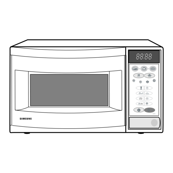
Page 6: Control Panel
Clock Setting Button Power Level Selection Button Timer Setting Button 10min Combi Button 1min Grill Button 10s. Stop Button 1 min + G643CR Standard Boost Button 3-2 Features & External Views Ventilation Slot Heater Light Door Safety Interlock Holes Auto Auto Control Panel lbs. -
Page 7: Disassembly And Reassembly
4-1 Replacement of High Voltage Transformer 1. Discharge the high voltage capacitor. 2. Disconnect all the leads. 3. Remove the mounting bolts. 4. Reconnect the leads correctly and firmly. H. V. Trans Screws Samsung Electronics... -
Page 8: Replacement Of Door Assembly
1. Insertion depth of the thin metal plate should be 0.5mm or less. 4-3-4 Removal of Key Door & Spring Remove pin hinge from Door "E" Detach spring from Door "E" and key door. Door "E" Key Door Spring Samsung Electronics... -
Page 9: Replacement Of Fuse/Drive Motor
1. Take out the outer panel ceramic 2. Disconnect the connectors from the heater ceramic Heater Bracket Upper and wire leade. 3. Remove screws securing the bracket upper to the oven cavity. 4. Remove one screw securing the bracket heater. Screw Bracket Heater Samsung Electronics... - Page 10 3. When installing new membrane key board, make sure that the surface of escutcheon base is cleaned sufficiently so that any problems Membrane (shorted contacts or uneven surface) can be Panel avoided. Samsung Electronics...
-
Page 11: Alignment And Adjustments
3. Before touching any oven components or wiring, always unplug the oven from its power source and discharge the high voltage capacitor. 5-1 High Voltage Transformer 1. Remove connectors from the transformer terminals Filament Terminals and check continuity. 2. Normal resistance readings are as follows: MODEL G643CR Secondary Approx. 130Ω Filament Approx.0Ω Primary Approx.1.700Ω... -
Page 12: High Voltage Capacitor
∞ procedures. Primary switch ∞ Monitor switch (COM-NC) 5. Confirm that the gap between the switch ∞ Monitor switch (COM-NO) housing and the switch actuator is no more than ∞ Door Sensing S/W 0.5mm when door is closed. Samsung Electronics... - Page 13 5. After heating for 2 minutes, measure the water temperature in each beaker. 6. Microwave heat distribution rate can be calculated as follows: Minimum Beaker Temperature Rise Heat Distribution = X 100(%) Maximum Temperature Rise The result should exceed 65%. Cooking Tray Samsung Electronics...
-
Page 14: Troubleshooting
H.V.Transformer component test procedure and replace if it is H.V.Capacitor defective. H.V.Diode, H.V.Fuse Magnetron 4. Open or loose wiring of power relay 5. Defective primary latch switch 6. Defective power relay or Ass'y PCB Replace PCB main. Samsung Electronics... - Page 15 Use plastic wrap or cover with a lid. Stir once or twice while cooking foods such as soup, cocoa, or milk. Noise from the turntable motor Noise may result from the motor. Replace turntable motor. when it starts to operate. Samsung Electronics...
-
Page 16: Exploded Views And Parts List
7. Exploded Views and Parts List 7-1 Exploded Views... -
Page 17: Main Parts List
M 34 DE74-70002A RACK-WIRE;MSWR10 3 220 80 M 35 DE39-30097B ASSY WIRE LEAD-G;L100 MBQ45 GRILL 79224-0056-01 M 36 DE61-50323A BRACKET-UPPER;ALSTAR T0.6 W385 L205 M6245G 73011-0243-00 M 37 DE71-60009A COVER-MOTOR;P.P TB53 M745 : Warning : Option Parts :Electrostatically Sensitive Devices Samsung Electronics... -
Page 18: Door Parts List
7-5 Body Latch Parts List Ref. No. Parts No. Description/Specification Q'ty Remarks Old No. DE66-90001A LEVER-SWITCH;P.O.M (F20-02) 2 6 NTR 2ND-W-P/ 3405-000178 SW-MICRO;VP-533A-OF-PS(T85) 250V,15A,20 73579-203-207 3405-000175 SW-MICRO;VP-531A-OF(T85) 250V,15A,200GF 73579-203-208 3405-000178 SW-MICRO;VP-533A-OF-PS(T85) 250V,15A,20 73579-203-207 DE66-40001A LATCH-BODY;POM (F20-02) 40GR NTR Samsung Electronics... -
Page 19: Standard Parts List
SCREW-ASSY TAPTITE;PH TC M4X8 SWRCH18A ZPC2 MWM-PN A0103-0010 DE60-10098A SCREW-ASSY TAPTITE;PH TC M4X8 SWRCH18A ZPC2 MO/DRI A0103-0010 DE60-10088A SCREW-TAP PH;PH M3 L8 FEFZY PLAIN 77168-530-081 DE60-10088A SCREW-TAP PH;PH M3 L8 FEFZY PLAIN 77168-530-081 DE02-00029A TAPE-SCOTCHPAR;PPOLYESTER 3M-893 W50 TR-CUS 70859-800-311 Samsung Electronics... - Page 20 8. P.C.B Diagrams 8-1 P.C.B Diagrams Samsung Electronics...
- Page 21 A4060-0009 TR-W/RESISTOR;KSR2005 300MW -100MA -50V EBP TR09 A4106-0154 DIODE-ZENER;TZP5.1B 5.1/5.7V 40MA T 1W ZD01~03 A6010-0461 CONNECTOR-WAFER;YW396-04V WHT CN04 DE13-20009A IC;KA7533 DIP IC02 DE39-60001A WIRE-SO COPPER;PI0.6 SN T 52MM J01~28 DE60-60012A PIN-EYELET;ID2.1 OD2.5 L3.0 SN BSP T0.25 SN E1~8 Samsung Electronics...
-
Page 22: Schematic Diagrams
SYMBOL COLOR DOOR : P.C.B PATTERN BROWN MAIN POWER INRUSH GRILL SENSING BLUE : P.C.B IN/OUT RELAY RELAY RELAY RELAY SWITCH L.V.T ORANGE POINT WHITE BLACK YELLOW DOOR SENSING MONITOR PRIMARY GREEN LATCH LATCH SWITCH YELLOW/GREEN SWITCH SWITCH Samsung Electronics...