Accu-Chek Inform II Operator's Manual
Hide thumbs
Also See for Inform II:
- Operator's manual (248 pages) ,
- Quick reference manual (39 pages) ,
- Manual (39 pages)
Table of Contents
Advertisement
Quick Links
Advertisement
Table of Contents

Related Manuals for Accu-Chek Inform II


Summary of Contents for Accu-Chek Inform II
- Page 1 ACCU-CHEK Inform II ® BLOOD GLUCOSE MONITORING SYSTEM Operator’s Manual...
- Page 2 Manual version Revision date Changes Version 1.0 2012-10 New document Version 2.0 2013-02 Upgrade to FW 03.04; Revise critically ill statement Version 3.0 2013-03 Update cleaning and disinfecting chapter...
- Page 3 CCU- Inform II System ® Operator’s Manual ©2013 Roche Diagnostics. All rights reserved. 05234646002 2013-03 USA...
- Page 4 Roche Diagnostics. Please send questions or comments about this manual to your local Roche representative. ACCU-CHEK, ACCU-CHEK INFORM and COBAS are trademarks of Roche. All other trademarks are the property of their respective owners. The Wi-Fi CERTIFIED Logo is a certification mark of the Wi-Fi Alliance.
-
Page 5: Table Of Contents
Introduction Before you start ............................11 Intended use ............................11 Important information regarding use ..................12 If you need help ..........................13 Note on the use of “base unit” in this manual .................13 Note on illustrations in this manual .....................13 What can the system do for you? ....................14 Important safety instructions and additional information ............15 Important information regarding safety ..................16 Disposal of the system ........................17... - Page 6 Patient Glucose Testing Information regarding blood glucose testing ..................37 Preparing to test ..........................38 Performing a patient glucose test ......................39 Overview of test procedure ......................39 Entering or selecting the patient ID .....................39 Entering the patient ID manually ....................41 Selecting the patient ID from a list ....................42 Entering a patient ID with barcode scanner ................43 Confirming or selecting the test strip lot ...................44 Inserting test strips ..........................45...
- Page 7 Storing Test Strip, Control Solution, and Linearity Solution Information in the Meter Storing information about test strips ....................65 Transferring code key information to the meter ..............66 Editing test strip data ........................68 Storing control solution information ....................70 Entering the lot number of the control solution ..............70 Selecting a stored lot number as the current lot number ............74 Storing linearity test information ......................76 Entering the lot number of the linearity test ................76...
- Page 8 General operating conditions ......................123 Storage ..............................124 Cleaning and disinfecting the ACCU-CHEK Inform II system ..........124 Guide to cleaning and disinfecting the ACCU-CHEK Inform II system .........125 Cleaning and disinfecting the meter ..................125 Acceptable cleaning / disinfecting agents ................126 What to clean / disinfect........................127 Technical Assistance ........................127...
- Page 9 Meter reset ............................139 General Product Information Technical data ............................141 Further Information ..........................143 Ordering ..............................143 Accu-Chek Inform II Operator’s Manual and Quick Reference Guide ......143 Reagents and Solutions .........................143 Information about software licenses ..................144 Contact Roche ..........................144 Appendix Table of configuration options ......................145 Example of barcode symbologies ......................154...
- Page 10 This page intentionally left blank.
-
Page 11: Introduction
Introduction Before you start Intended use The ACCU-CHEK Inform II test strips are for use with the ® ACCU-CHEK Inform II meter to quantitatively measure glucose (sugar) in venous whole blood, arterial whole blood, heel stick neonatal, or fresh capillary whole blood samples drawn from the fingertips as an aid in monitoring the effectiveness of glucose control. -
Page 12: Important Information Regarding Use
The FDA, CDC, and CMS recommend that Point of Care blood testing devices such as the ACCU-CHEK Inform II meter should be used only on one patient and not shared. If dedicating blood glucose meters to a single... -
Page 13: If You Need Help
Note on the use of “base unit” in this manual Unless otherwise specified, the term “base unit” refers to both the ACCU-CHEK Inform II Base Unit and the ACCU-CHEK Inform II Base Unit Light. Note on illustrations in this manual... -
Page 14: What Can The System Do For You
Introduction What can the system do for you? The ACCU-CHEK Inform II system has the following fea tures and properties: Perform patient blood glucose tests and glucose control tests with control solution. Automatically record all relevant data for the application, which includes: –... -
Page 15: Important Safety Instructions And Additional Information
Important safety instructions and additional information This section explains how safety-related messages and information related to the proper handling of the system are presented in this ACCU-CHEK Inform II manual. Please read these passages carefully. The safety alert symbol alone (without a signal word) -
Page 16: Important Information Regarding Safety
Operators need to adhere to Standard Precautions when handling or using the ACCU-CHEK Inform II system. All parts of this system should be considered potentially infectious and are capable of transmitting blood-borne pathogens between patients and healthcare professionals. -
Page 17: Disposal Of The System
Introduction Disposal of the system Infection by a potentially biohazardous instrument The ACCU-CHEK Inform II system or its components must be treated as potentially biohazardous waste. WARNING Decontamination (i.e., a combination of processes including clean ing, disinfection and/or sterilization) is required before reuse, recycling, or disposal. -
Page 18: Battery Pack
Do not dispose of the battery pack with normal domestic waste. As a component of the ACCU-CHEK Inform II sys tem, it must be deemed as potentially biohazardous. Treat it accordingly. See “Disposal of the system” on page 17. -
Page 19: Touchscreen
Do not stare directly into the laser beam. WARNING Electrostatic discharge (ESD) The ACCU-CHEK Inform II system complies with both the electromagnetic immunity requirements and radio inter ference immunity requirements at the frequency and test levels according to EN ISO 15197 Annex A. The... -
Page 20: Local Area Network: Protection From Unauthorized Access
Wired network connection If connected to a local area network, the ACCU-CHEK Inform II Base Unit or ACCU-CHEK Inform II Base Unit HUB must be protected against unauthorized access. For additional information about the ACCU-CHEK Inform II Base Unit or ACCU-CHEK Inform II Base Unit HUB, refer to the ACCU-CHEK Inform II Base Unit HUB Operator’s... -
Page 21: Radiofrequency Radiation Exposure Information
Introduction Radiofrequency radiation exposure information Glossary: “FCC” stands for “Federal Communications Commission” (USA). “RSS” stands for “Radio Standards Specification” (Canada) The Industrial, Scientific and Medical (ISM) frequencies (802.11b and 802.11g use 2.4 GHz) may contain emis sions from microwave ovens, heaters, and other non- communication devices. - Page 22 The electromagnetic environment in which the ACCU- CHEK Inform II device will be operated should be thoroughly evaluated prior to operation of the device.
- Page 23 Introduction This equipment has been tested and found to comply with the limits for a Class B digital device, pursuant to Part 15 of the FCC Rules. These limits are designed to provide reasonable protection against harmful interfer ence in a residential installation.
-
Page 24: System Components
Introduction System components The ACCU-CHEK Inform II system includes the following components and accessories: Meter Code key reader Base unit with power supply Accessory box (not included) The system can be configured by two different methods: Configuration via the Setup function on the meter... -
Page 25: Overview Of The Meter
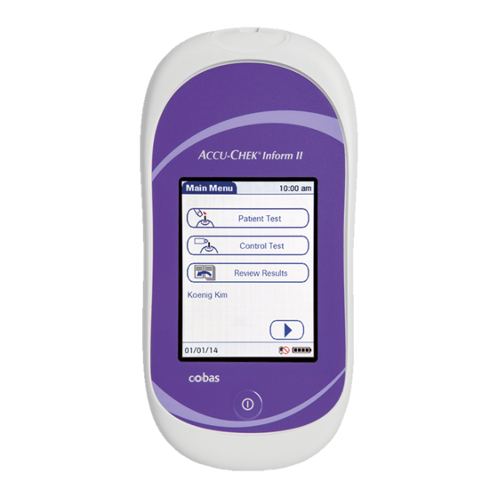
Introduction Overview of the meter The meter has the following elements: Test strip port Insert the test strip here. Touchscreen (touch-sensitive display) This screen allows you to perform patient tests, perform control tests, and review results. To select any of these functions, simply touch the button on the screen. -
Page 26: Overview Of The Code Key Reader
Introduction Overview of the code key reader Test strip vials include a code key. This code key is read by the code key reader and the data is sent to the meter. For additional information about the code key reader, see Chapter 6. -
Page 27: Overview Of The Base Unit
– Lights up blue: Configuration mode (ACCU-CHEK Inform II Base Unit only) Jack for the power supply unit provided Removable mount for wall installation The ACCU-CHEK Inform II Base Unit has the following additional elements: Network connection — LAN, Ethernet (RJ45) USB connection... -
Page 28: Overview Of The Accessory Box
You need the following reagents to perform patient tests and glucose control tests: ACCU-CHEK Inform II Test Strips ACCU-CHEK Inform II Control Solutions: Available for purchase separately, consists of two 2.5 mL bottles. One bottle contains the Level 1 (Lo) control, while the other bottle contains the Level 2 (Hi) control. -
Page 29: Instructions For Initial Setup
Introduction Instructions for initial setup The meter must be configured prior to initial use. During this setup, the following parameters are configured: Date and time format Input mode for Patient ID Input mode for Operator ID Glucose controls: Type and schedule Results screen for glucose control Comments for entry after a test Settings for data transfer... - Page 30 Introduction This page intentionally left blank.
-
Page 31: Powering Up And Entering An Operator Id
Powering Up and Entering an Operator ID Powering Up and Entering an Operator ID Powering up the meter Press and release the On/Off button . The meter is now on. The Power Up screen appears. Check in the Power Up screen whether the date (lower left) and time (upper right) are displayed correctly. -
Page 32: Adjusting The Display
Powering Up and Entering an Operator ID Adjusting the display Using the Display options, you can adjust display param eters to your needs: Adjust the display contrast to the ambient light conditions. Set the time interval for activating the Low Power Mode, which reduces the display contrast after a configurable time without activity (e.g., touching the screen) to conserve energy. -
Page 33: Enabling/Disabling The Rf Card
WARNING WLAN functionality of the ACCU-CHEK Inform II system using the guidelines of your facility. If the RF card is activated, the (RF OFF) icon is dis played as a button in the Power Up screen. -
Page 34: Closing Startup
Powering Up and Entering an Operator ID Closing startup Once you have completed all the necessary changes, touch to proceed to the screen used to enter the operator ID, or wait 5 seconds and the meter automatically proceeds to the screen used to enter the operator ID. -
Page 35: Entering An Operator Id With Barcode Scanner
Powering Up and Entering an Operator ID Entering an operator ID with barcode scanner When the screen for entering the operator ID is dis played: Press and release . The button now appears with a black background (during the scan). Hold the meter so that the window of the barcode scanner is approximately 4-8 inches above the barcode you wish to read. -
Page 36: Entering The Operator Id Manually
Powering Up and Entering an Operator ID Entering the operator ID manually When the screen for entering the operator ID is displayed: Touch the letters or numbers to enter the ID. Use the following buttons to toggle between ranges of characters: –... -
Page 37: Patient Glucose Testing
Patient Glucose Testing Patient Glucose Testing Information regarding blood glucose testing Before performing a blood glucose test, observe the following safety precautions: Observe the applicable regulations and directives for hygiene and safety when collecting blood samples. Observe the applicable regulations and directives for disposing of potentially infectious samples and materials. -
Page 38: Preparing To Test
Patient Glucose Testing Preparing to test For more detailed information regarding the ACCU-CHEK Inform II test strip, refer to the package insert for instructions for use, performance characteristics, and limitations of the system. The following requirements must be met before you can perform a test: The ACCU-CHEK Inform II test strips are available. -
Page 39: Performing A Patient Glucose Test
Patient Glucose Testing Performing a patient glucose test Overview of test procedure A patient glucose test comprises the following steps: Enter the patient ID. This can be done either manually or by using the barcode scanner. Confirm that the test strip lot matches the test strips in use (if configured). - Page 40 Patient Glucose Testing You now have three different options, depending on setup, for assigning the subsequent test to a patient. The patient ID function can be configured by your system administrator to: Enter any combination of up to 20 alphanumeric characters, with specified minimum and maximum lengths.
-
Page 41: Entering The Patient Id Manually
Patient Glucose Testing Entering the patient ID manually Use the displayed keypad to enter the patient ID. You can select characters in the same manner as when entering an operator ID. Touch the letters or numbers to enter the ID. Use the following buttons to toggle between ranges of characters: –... -
Page 42: Selecting The Patient Id From A List
Patient Glucose Testing Selecting the patient ID from a list Choose the patient ID from a list*, if a list has been down loaded to the meter (from the data management system). Touch to scroll up or down in the list. If one of the buttons is hidden, you have reached the top or bottom of the list. -
Page 43: Entering A Patient Id With Barcode Scanner
Patient Glucose Testing Entering a patient ID with barcode scanner When the screen for entering the patient ID is displayed: Press and release . The button now appears with a black background (during the barcode scan). Hold the meter so that the window of the barcode scanner is approximately 4-8 inches above the barcode you wish to read. -
Page 44: Confirming Or Selecting The Test Strip Lot
Patient Glucose Testing Confirming or selecting the test strip lot Once you have entered and confirmed the patient ID, you are asked to choose the lot number for the test strips. Compare the number displayed by the meter to the number on the label of the test strip vial. -
Page 45: Inserting Test Strips
Remove the test strip from the test strip vial and close the vial with the cap. Hold the test strip so the lettering “ACCU-CHEK” is facing upward. Slide the test strip into the test strip port as far as it goes in the direction indicated by the arrows on the test strip. -
Page 46: Applying A Blood Sample
Patient Glucose Testing Applying a blood sample Once the meter has detected the test strip, you are prompted to apply a blood sample. Wait until the flashing drop appears in the display before applying the blood. The meter beeps again. Apply the drop of blood to the front edge (yellow dosing area) of the test strip. -
Page 47: Results Screen
Patient Glucose Testing Results screen The hourglass icon indicates the test is running. When the test is completed and the result is ready, the meter beeps again. When the result is displayed, a message or warning may also appear (depending on system configuration) notify ing you if the result exceeds the specified limit values. - Page 48 (test strips and meter) and is the only range which cannot be configured. With ACCU-CHEK Inform II test strips this fixed range is 10 to 600 mg/dL (0.6 to 33.3 mmol/L). If a result falls outside this range, the message HI or LO appears, i.e., the result cannot be...
- Page 49 Patient Glucose Testing The following messages may appear in addition to the standard test result: CR LO (below the Critical Range threshold, but within the Reportable Range) CR HI (above the Critical Range threshold, but within the Reportable Range) RR LO (below the Reportable Range threshold, but within the System Measurement Range) RR HI (above the Reportable Range threshold, but within the System Measurement Range)
-
Page 50: Adding Comments
Patient Glucose Testing Adding comments You can add up to a total of three comments to a test result. Com ments can provide, for example, additional information about the test conditions or the patient. Of these three comments only one can be a custom comment;... -
Page 51: Glucose Control Testing
Glucose Control Testing Glucose Control Testing Information regarding glucose control tests Observe the applicable regulations and directives of the responsible regulatory agencies when performing glu cose control tests. Accurately testing known levels of glucose ensures that the system and your technique used in testing give accu rate results on patient tests. -
Page 52: Glucose Control Testing Intervals
Glucose Control Testing Glucose control testing intervals Intervals between running glucose control tests are determined by your facility. These intervals are entered when the system is configured. At the end of the speci fied interval (or after a specific event such as starting to test with a new test strip lot), a warning is displayed when the meter is switched on and when the Glucose Test function is selected. -
Page 53: Information Stored During Glucose Control Testing
Glucose Control Testing Information stored during glucose control testing The following information is stored for every glucose con trol test using control solution: Glucose control test result Lot number of the control solution Operator ID (if configured) Level of control solution (L1 or L2) Lot number of the test strips Time and date of test Comments (if applicable) -
Page 54: Performing Glucose Control Tests
Glucose Control Testing Performing glucose control tests Overview of test procedure A glucose control test using control solution comprises the following steps: Select the desired level of control solution for the test. Check the lot number of the control solution. Check the lot number of the test strips. -
Page 55: Starting A Glucose Control Test
Glucose Control Testing Starting a glucose control test After preparing the meter as described, you can proceed to the steps directly related to control testing: From the Main Menu screen touch Control Test. In the Control Test screen, the levels available for the control solution are displayed. -
Page 56: Confirming Or Selecting The Lot Number For Control Solutions
Glucose Control Testing Confirming or selecting the lot number for control solutions Once you have selected the level, you are asked to con firm or enter the lot number of the control solution. Com pare the number displayed by the meter to the number on the label of the control solution bottle. -
Page 57: Confirming Or Selecting The Test Strip Lot
Glucose Control Testing Confirming or selecting the test strip lot Once you have entered and confirmed the lot number of the control solution, you are asked to choose the test strip lot number. Compare the number dis played by the meter to the number on the label of the test strip vial. -
Page 58: Inserting Test Strips
Remove the test strip from the test strip vial and close the vial with the cap. Hold the test strip so the lettering “ACCU-CHEK” is facing upward. Slide the test strip into the test strip port as far as it goes in the direction indicated by the arrows on the test strip. -
Page 59: Applying The Control Solution
Glucose Control Testing Applying the control solution Once the meter has detected the test strip, you are prompted to apply the control solution. Wait until the flashing drop appears in the display before applying the control solution. Apply a drop of glucose control solution to the front edge of the test strip. -
Page 60: Results Screen
Glucose Control Testing Results screen The hourglass icon indicates the test is running. When the test is completed and the result is ready, the meter beeps again. Depending on configuration, the result is displayed either as a value or only as a qualitative result Pass or Fail. Your system may be configured to disallow further testing until all the required glucose control levels are successfully run (QC Lockout). -
Page 61: Performing A Stat Test
Glucose Control Testing Performing a STAT test The meter can be configured to allow a STAT patient glu cose test to be run even if the meter is in QC Lockout or Download Lockout. This option is to be used in situations with critical patients. - Page 62 Glucose Control Testing This page intentionally left blank.
-
Page 63: Review Results
Review Results Review Results Displaying test results from the memory Information stored in data records for test results When you retrieve the data record for stored test results, the following information is displayed. Patient ID, glucose control, or sample ID The test result The lot numbers of the reagents used for glucose control and linearity tests... - Page 64 Review Results Touch an entry in the list to display the related details. Touch Patient, if you wish to display results for a specific patient only. – If you touch Patient from the full list view, you will be asked to enter the patient ID manually or via barcode scanner.
-
Page 65: Storing Test Strip, Control Solution, And Linearity Solution Information In The Meter
Storing Test Strip, Control Solution, and Linearity Solution Information in the Meter Storing Test Strip, Control Solution, and Linearity Solution Information in the Meter Storing information about test strips Each box of test strips contains a code key. Each code key belongs to a single lot number and provides impor tant information about the lot-specific properties of the test strip. -
Page 66: Transferring Code Key Information To The Meter
Storing Test Strip, Control Solution, and Linearity Solution Information in the Meter Transferring code key information to the meter The following description assumes that the meter is pow ered on and the main menu is displayed. Touch to open the Main Menu 2 screen. Touch Strip Lots to open the related menu. - Page 67 Storing Test Strip, Control Solution, and Linearity Solution Information in the Meter Place the code key reader on a level surface such as a bench. Hold the meter 4-6 inches above the code key reader so that a connection can be made between the two infrared windows.
-
Page 68: Editing Test Strip Data
Storing Test Strip, Control Solution, and Linearity Solution Information in the Meter Information about the expiration date and parameters for control solutions is subsequently displayed. Touch to store the data for this test strip lot number in the meter without changes, or Touch to modify the data for this test strip lot number before storing it in the meter. - Page 69 Storing Test Strip, Control Solution, and Linearity Solution Information in the Meter The parameters for control solutions consist of four sepa rate values. Use the keypad to enter the desired values one after another: – Minimum limit value for Level 1 –...
-
Page 70: Storing Control Solution Information
Storing Test Strip, Control Solution, and Linearity Solution Information in the Meter Once you have finished updating the test strip information, you can use the next screen to select the lot number you are currently editing as the current lot number. The current lot number is provided automatically for use with subsequent tests. - Page 71 Storing Test Strip, Control Solution, and Linearity Solution Information in the Meter Storing control solution information Glucose control solution lot information can be entered before testing, if lot editing has been allowed at the meter level in the setup, and appears in a list for operators to refer to.
- Page 72 Storing Test Strip, Control Solution, and Linearity Solution Information in the Meter Select the level (L1/Lo or L2/Hi). Use the keypad to enter the lot number. Touch to confirm the entered lot number, or Press and release to read the lot number from the control solution bottle via barcode scanner.
- Page 73 Storing Test Strip, Control Solution, and Linearity Solution Information in the Meter Once you have finished updating the control solution infor mation, you can use the next screen to select the lot number you are currently editing as the current lot number.
-
Page 74: Selecting A Stored Lot Number As The Current Lot Number
Storing Test Strip, Control Solution, and Linearity Solution Information in the Meter Selecting a stored lot number as the current lot number You can select any stored lot number as the current lot number. Touch in the main menu to open the Main Menu 2 screen. - Page 75 Storing Test Strip, Control Solution, and Linearity Solution Information in the Meter Touch the lot number you wish to select as the current lot number. This opens the related detail view. Touch Make Current to make the lot number the current lot number.
-
Page 76: Storing Linearity Test Information
Storing Test Strip, Control Solution, and Linearity Solution Information in the Meter Storing linearity test information Observe the applicable regulations and directives of the responsible regulatory agencies when performing linear ity tests. Entering the lot number of the linearity test The following description assumes that the meter is pow ered on and the main menu is displayed. - Page 77 Storing Test Strip, Control Solution, and Linearity Solution Information in the Meter Use the keypad to enter the linearity lot number. Touch to confirm the entered linearity lot number. Enter the expiration date (use two digits and leading zero, if necessary) and touch confirm the expiration date you have entered.
-
Page 78: Selecting A Stored Lot Number As The Current Lot Number
Storing Test Strip, Control Solution, and Linearity Solution Information in the Meter Selecting a stored lot number as the current lot number You can select any stored lot number as the current lot number. Touch in the main menu to open the Main Menu 2 screen. - Page 79 Storing Test Strip, Control Solution, and Linearity Solution Information in the Meter Touch the linearity lot number you wish to select as the current lot number. This opens the related detail view. Touch Make Current to make this lot number the current lot number.
- Page 80 Storing Test Strip, Control Solution, and Linearity Solution Information in the Meter This page intentionally left blank.
-
Page 81: Linearity Testing
For information about sources for products required during linearity testing, call your local Roche representative or for technical assistance contact ACCU-CHEK Customer Care. Linearity tests can help you to check the function and accuracy of the entire system over the full range of spec ified values. -
Page 82: Information Stored During Linearity Testing
Linearity Testing Information stored during linearity testing The following information is stored for every linearity test: Test result Lot number of the linearity solution Level of linearity solution (L1 to L6) Operator ID (if configured) Lot number of the test strips Time and date of test Comments (if applicable) Linearity test kit... -
Page 83: Performing A Linearity Test
Linearity Testing Performing a linearity test Overview of test procedure A linearity test comprises the following steps: Check the lot number of the linearity solutions. Check the lot number of the test strips. Perform the test with a minimum of three linearity solutions. -
Page 84: Confirming Or Selecting The Lot Number For Linearity Test Kits
Linearity Testing Confirming or selecting the lot number for linearity test kits You are now prompted to confirm or enter the lot number of the linearity test kit. Compare the number displayed by the meter to the number on the label of the linearity test kit. -
Page 85: Inserting Test Strips
Remove the test strip from the test strip vial and close the vial again with the cap. Hold the test strip so the lettering “ACCU-CHEK” is facing upward. Slide the test strip into the test strip port as far as it will go in the direction indicated by the arrows on the test strip. -
Page 86: Applying A Linearity Test Sample
Linearity Testing Applying a linearity test sample Once the meter has detected the test strip, you will be prompted to apply the linearity solution. Wait until the flashing drop appears in the display before applying the solution. Apply a drop of the linearity solution to the front edge of the test strip. -
Page 87: Results Screen
Linearity Testing Results screen The hourglass icon indicates the test is running. When the test is completed and the result is ready, the meter beeps again. You can add comments to a test result (as with blood glucose tests, see page 50). If you do not wish to add a comment to the test result, touch to continue to the next level of the linearity... - Page 88 Linearity Testing This page intentionally left blank.
-
Page 89: Proficiency Testing
Proficiency Testing Proficiency Testing Information regarding proficiency tests Observe the applicable regulations and directives of the responsible regulatory agencies when performing profi ciency tests. Blood glucose proficiency tests are run on samples whose values are unknown to the operator performing the test. -
Page 90: Information Stored During Proficiency Testing
Proficiency Testing Information stored during proficiency testing The following information is stored for every proficiency test: Test result Sample ID Lot number of the test strips Time and date of test Comments (if applicable) Operator ID (if configured) For blood glucose proficiency tests, the sample ID (instead of patient ID) must be stored as identification. -
Page 91: Performing A Proficiency Test
Proficiency Testing Performing a proficiency test Overview of test procedure A proficiency test comprises the following steps: Enter a sample ID for the proficiency sample. Check the lot number of the test strips. Perform the actual test with the proficiency sample. Starting a proficiency test The following description assumes that the meter is powered on and the main menu is displayed. -
Page 92: Entering The Proficiency Sample Id
Proficiency Testing Entering the proficiency sample ID You will now be asked to enter the sample ID. Use the keypad to manually enter the sample ID, or Press and release to read the sample ID from the sample vial via barcode scanner (see page 35). -
Page 93: Inserting Test Strips
Remove the test strip from the test strip vial and close the vial with the cap. Hold the test strip so the lettering “ACCU-CHEK” is facing upward. Slide the test strip into the test strip port as far as it will go in the direction indicated by the arrows on the test strip. -
Page 94: Applying A Proficiency Sample
Proficiency Testing Applying a proficiency sample Once the meter has detected the test strip, you are prompted to apply the proficiency sample. Wait until the flashing drop appears in the display before applying the sample. Apply a drop of sample to the front edge of the test strip. -
Page 95: Results Screen
Proficiency Testing Results screen The hourglass icon indicates the test is running. When the test is completed and the result is ready, the meter beeps again. The result is displayed as a numerical value, unless it falls outside the system measurement range. In this case, the message HI or LO is displayed. - Page 96 Proficiency Testing This page intentionally left blank.
-
Page 97: Initial Startup
To ensure continuous safe and reliable operation, use NOTICE only the power supply unit provided for the ACCU-CHEK Inform II system (for ordering information see page 143). Slide the base unit upward and remove it from the wall mount (if in use). -
Page 98: Installing Or Replacing The Battery Pack
Installing or replacing the battery pack When shipped, the battery pack is not installed in the ACCU-CHEK Inform II meter. After installing a new battery pack, the meter should be charged for three hours in the base unit before testing. -
Page 99: Removing The Battery Pack
Initial Startup Removing the battery pack If a battery pack is already installed, make sure that the meter is switched off. Place the meter face down on a level surface. Using a Torx screwdriver size T5, remove the two screws holding the battery pack in place. Carefully remove the battery pack from the meter. -
Page 100: Installing The Battery Pack
Initial Startup Installing the battery pack Loosen the screws on the battery pack until they are protruding about 2/10 inch. Position the battery pack alongside the meter so that the plug connector is level with the socket inside the meter. Plug the connector plug into the socket. - Page 101 Initial Startup Place the tapering end of the battery pack on the small ledge of the opening and push down like a lid to close (as shown in the illustration below). Make sure that the plug connector wires slide into the groove provided for them on the battery pack.
- Page 102 Initial Startup Place a ruler across the back of the meter to check that the battery pack is properly positioned. The ruler should lie completely flat, touching both sides of the meter on the left and right of the battery pack (see left image above).
-
Page 103: Docking The Meter
Note: The following displays appear on the meter when it is docked in an ACCU-CHEK Inform II Base Unit or an ACCU-CHEK Inform II Base Unit Light and communicating. The same displays appear whether the meter is transferring data via base unit or via RF card (wireless connection). - Page 104 Initial Startup This display is visible when communication is still active but the meter is busy processing the data received or waiting for the next data message from the DMS. This display is visible when software updates are trans ferred to the meter. This display is visible when software updates are trans ferred to the meter.
-
Page 105: Initial Setup On The Meter
Initial Startup Initial setup on the meter There are two ways to customize the setup of the meter: directly on the meter (see the following menu overview) or via the data management system (see Appendix A). The two methods differ according to the range of options available. -
Page 106: Menu Overview
Initial Startup Menu overview The following tables contain a brief overview of the menu structure. The menus can be used to operate the meter fully and enter the most important basic settings. Main Menu Observer Log in – Enter Observer ID –... - Page 107 Initial Startup Main Menu 2 Maintenance – Add Comment – Maintenance Result Proficiency – Enter Sample ID – Verify Test Strip Lot – Insert Test Strip – Apply Sample – View Test Results – Add Comments Strip Lots – View Lot List –...
- Page 108 Initial Startup Admin Menu Admin – Language – Date/Time – Setup Language – German – French – Spanish – Italian – Dutch – Swedish – English – Danish – Portuguese Date/Time – Enter Current Date – Enter Current Time Setup Menu Date/Time Options –...
-
Page 109: Opening The Setup Menu
Initial Startup Opening the Setup Menu The following description assumes that the meter is powered on and the main menu is displayed. All settings described here are configured via the Setup Menu. To open the Setup Menu, proceed as follows: Touch in the Main Menu to open the Main Menu 2 screen. -
Page 110: Date And Time Format
Initial Startup Date and time format Use this menu to select the date and time format for the display. You can also choose whether the operator is allowed to edit date and time (optionally with password required). Touch the desired option to enable it: Date/Time Editing –... -
Page 111: Display Options And Optional Tests
Initial Startup Display options and optional tests Use this menu to select the unit of measure for test results and enable or disable optional tests. Touch the desired option to enable it: Result Units – mg/dL – mmol/L Enable Tests –... -
Page 112: Options For Test Strips
Initial Startup Options for test strips This menu allows you to select options for handling lot numbers and specify whether the operator is allowed to edit the expiration date and limit values on the meter (optionally with password required). Touch the desired option to enable it: Reagent Editing –... - Page 113 Initial Startup On the second settings screen, you can select options for handling lot numbers with glucose control and linearity tests. Touch the desired option to enable it: Control Lot Verification – Display only: The lot number is shown on-screen but the operator cannot confirm it or select a different lot number.
-
Page 114: Options For Glucose Control Tests
Initial Startup Options for glucose control tests This menu contains options that allow you to specify whether and at what intervals glucose control tests are performed. If you require control tests, check your set tings for STAT tests (see page 111). Touch the desired option to enable it: Control Frequency –... -
Page 115: Value Ranges (Normal, Critical, Reportable)
Initial Startup Value ranges (normal, critical, reportable) This menu allows you to set limit values for results as Normal, Critical, or Reportable. Results outside these limits will be flagged to alert you of this event. The Reportable Range allows the system administrator to set an institution defined range for reporting patient results. -
Page 116: Options For Operator Id Entry
Initial Startup Options for Operator ID Entry This menu allows you to specify if and how operator login is performed. Touch the desired option to enable it: Operator Entry – None: The meter can be used without operator login. – Prompt or Prompt (numeric only): Operator login is required. -
Page 117: Patient Id Options
Initial Startup Patient ID options This menu allows you to specify the criteria for entering a patient ID. Touch the desired option to enable it: Patient Entry – Prompt or Prompt (numeric only): The Patient ID can be entered manually via keypad or via barcode scanner. -
Page 118: Creating A Setup Password
Initial Startup Creating a setup password This screen allows you to create a password for all the settings described in this chapter. The password ensures that only authorized persons can make changes to the setup. Please note that password protection can only be reset or modified after entering the current password. -
Page 119: Setting The Date And Time
Initial Startup Setting the date and time This setting can be hidden or require entry of a password, based on configuration. Touch in the Main Menu to open the Main Menu 2 screen. Touch Admin. to open the Admin Menu. Touch Date/Time to begin entering the date. -
Page 120: Beeper Options
Initial Startup Beeper options This setting can be used to set the volume of the beeper. Touch in the Main Menu to open the Main Menu 2 screen. Touch Beeper to set the volume. Touch the button with the desired volume. When you touch a button, the meter will beep at the corresponding volume. -
Page 121: Diagnostics View
Initial Startup Diagnostics view Under Diagnostics you can find information about the system, such as software version, number of data records stored, and settings. Use this menu to display stored error messages and test the barcode scanner. Touch in the Main Menu to open the Main Menu 2 screen. -
Page 122: Unlocking A Download Lockout
Initial Startup Unlocking a Download Lockout When using a data management system for configura tion, a Download Lockout can be configured. This lockout prevents a meter from being used for testing, if the meter data have not been downloaded for a defined period of time. -
Page 123: 10 Maintenance And Care
Conditions for storage and shipping All information given on maintenance and care of the “base unit” in this chapter applies to both the ACCU-CHEK Inform II Base Unit and the ACCU-CHEK Inform II Base Unit Light. General operating conditions Please observe the following points to ensure the reliable... -
Page 124: Storage
Observe the limits for temperature and humidity when storing and using the meter (see Chapter 12). Cleaning and disinfecting the ACCU-CHEK Inform II system Cleaning and disinfecting the exterior surface of the meter is, at minimum, recommended daily for dedicated patient devices. -
Page 125: Guide To Cleaning And Disinfecting The Accu-Chek Inform Ii System
Maintenance and Care Guide to cleaning and disinfecting the ACCU-CHEK Inform II system Prior to cleaning and disinfecting a blood glucose testing equipment: Follow the infection control procedures of your institution when handling blood glucose testing equipment Wear gloves The gloves worn during cleaning and disinfecting should be... -
Page 126: Acceptable Cleaning / Disinfecting Agents
Maintenance and Care Acceptable To purchase approved disinfecting products, please refer to your facility’s Cleaning / guidelines, which may include instructions on direct purchase from the Disinfecting manufacturer or through an approved distributor. For additional Agents information on product availability for purchase, refer to manufacturer’s website: http://www.cloroxprofessional.com for Clorox Germicidal Wipes ®... -
Page 127: What To Clean / Disinfect
Assistance disinfecting of your meter system, stop using the system component and contact ACCU-CHEK Customer Care at 1-800-440-3638 for assistance: clouding of the touchscreen display, on/off button button malfunction, clouding of the infrared data port and/or barcode scanner, or quality control... -
Page 128: How To Clean And Disinfect The Accu-Chek Inform Ii System
Maintenance and Care How to clean and disinfect the ACCU-CHEK Inform II system Avoid getting liquid into the test strip port! Failure to follow these instructions may damage the meter and stop it from working properly. WARNING Do Not clean or disinfect the meter while performing a blood glucose or control test. -
Page 129: Cleaning The Meter
Maintenance and Care Cleaning the meter Place the meter on a level surface prior to cleaning. Power off the meter. Be certain that solutions contain acceptable active ingredients for cleaning the system. When using commercially available pre-moistened cleaning cloths, squeeze off excess cleaning solution or blot on a dry paper towel to remove any excess cleaning solu tion before cleaning the surface of the meter. -
Page 130: Disinfecting The Meter
Maintenance and Care Disinfecting the meter NOTE: The meter should be cleaned prior to each disinfection step. Remember to keep the meter on a level surface prior to disinfecting and powered off. Be certain that solutions contain acceptable active ingredients for disinfecting the system. When using commercially available pre-moistened disinfecting cloths, squeeze off excess disinfecting solution or blot on a dry paper towel to remove any excess disinfecting... -
Page 131: Logging Maintenance Activities
Maintenance and Care Logging maintenance activities Cleaning, disinfecting, and other maintenance activities can be logged in the meter. Make sure that all cleaning and disinfecting activities are complete and the system is thoroughly dry before switch ing on the meter. The following description assumes that the meter is powered on and the main menu is displayed. - Page 132 Maintenance and Care This page intentionally left blank.
-
Page 133: Troubleshooting
Troubleshooting 11 Troubleshooting The ACCU-CHEK Inform II meter continually checks its sys tems for unexpected and unwanted conditions. A troubleshooting table follows that will help you when the system is not performing as expected. Most concerns can be resolved quickly by referring to this table for help. - Page 134 – Run a glucose control test with a new test strip (see Chapter 4). – Repeat the test or proceed according to the requirements of your facility. – If the error persists, contact ACCU-CHEK Customer Care. Meter displays an error Insufficient amount of blood on the test strip. Type Bad Dose –...
- Page 135 – Press and release the On/Off button on the top of the meter. – Reset the meter by pressing the reset button (see page 139) – If the error persists, contact ACCU-CHEK Customer Care. Meter displays Unexpected SW Error Detection of an unexpected software error –...
- Page 136 Troubleshooting Display/symptom Possible solution Power off after time specified by – Press the On/Off button on the top of the meter. system administrator (default is 5 minutes, configurable by system administrator) Battery Low – Charge the battery by placing the meter in the base unit. Battery Critically Low –...
-
Page 137: Error Messages
Troubleshooting Error messages All error messages displayed by the system are accompanied by a description of the error and a possible solution. Take the action suggested on screen to resolve the prob lem. All messages, including purely informative messa ges, are preceded by a letter, identifying the message type, and a number. - Page 138 Troubleshooting Sample message type Description – E: Error; touch to confirm. To resolve the problem, take the actions suggested. – W: Warning; touch to confirm.
-
Page 139: Meter Reset
Troubleshooting Meter reset A meter reset can be performed to correct a number of unspecified errors (e.g., “frozen” screen, etc.). Use the fol lowing steps to perform a meter reset. Place the meter face down on a level surface. Press the reset button in the middle of the battery pack using a tool such as a screwdriver or a paper clip. - Page 140 Troubleshooting This page intentionally left blank.
-
Page 141: General Product Information
10 - 85% RH at 10 - 85% RH (non-condensing) (non-condensing) (non-condensing) Air pressure 0.7 to 1.06 bar 0.7 to 1.06 bar 70 to 106 kPa 70 to 106 kPa * ACCU-CHEK Inform II Base Unit Light: only red, green... - Page 142 Code 128, Code 39, Code 93, EAN 13**, Interleaved 2 of 5, Codabar., GS1 DataBar Limited * Not applicable to ACCU-CHEK Inform II Base Unit Light **EAN 13 barcodes are not recommended for identification of operators and patients. Specification Accessory box Code key reader Height 3.35 in / 85 mm...
-
Page 143: Further Information
0.6 mL The performance of this system has not been evaluated in the critically ill. For more information about the ACCU-CHEK Inform II test strip, refer to the package insert for instructions for use, performance characteristics, and limitations of the system. -
Page 144: Reagents And Solutions
“ROCHE HBU-BU Technical Note.pdf”. You can access these files by connecting the ACCU- CHEK Inform II Base Unit to a PC with the USB cable. For detailed instructions on how to do this, see the instruction sheet “Setting Up the Base Unit” included in the ACCU-CHEK Inform II Base Unit Kit. -
Page 145: A Appendix
General Product Information Appendix Table of configuration options This section provides an overview of all the settings avail able. The two rightmost columns describe the accessibility of a configuration parameter on the device (Setup Menu) and via the data management system (DMS). “Y”... - Page 146 General Product Information Subject/Attribute Range Default Device Comments requirement level: if out of ... 0: normal range (only valid if Comments required = 1) 1: critical range 2: reportable range 3: measurement range Custom comments 0: enabled 1: disabled Control lot verification 0: display only 1: yes / no confirmation 2: prompt for entry...
- Page 147 General Product Information Subject/Attribute Range Default Device Strip lot verification 0: display only 1: yes/no confirmation 2: list selection 3: scan only Linearity lot verification 0: display only 1: yes/no confirmation 2: prompt for lot entry Display Contrast 1 - 15 Formats and Language Date format 1: MM/DD/YY...
- Page 148 General Product Information Subject/Attribute Range Default Device Main menu 2 “Proficiency” allowed (if 0: disabled enabled, proficiency tests are allowed) 1: enable Admin menu “Setup” (if enabled, access to 0: disabled setup screens is possible) 1: enable Setup password 0 – 20 characters “”...
- Page 149 General Product Information Subject/Attribute Range Default Device * Depends on available DMS settings. Patient ID entry mode 0: Keyboard / Scan 1: List / Keyboard / Scan 2: Scan only 3: Prompt (numeric) Patient ID validation mode 0: none (Allowed characters: a-z, 0-9, 1: length “.”...
- Page 150 General Product Information Subject/Attribute Range Default Device QC time of day 6 POCT1-A data fields 06:00 00:00 – 23:59 09:00 12:00 15:00 18:00 22:00 QC time of day set 6 POCT1-A data fields 1 0 0 0 0 0 0 or 1 Result deletion Result deletion algorithm.
- Page 151 General Product Information Subject/Attribute Range Default Device DMS port (the port number to request 0 – 65,535 open socket from the DMS. Roche recommends use of port numbers ≥ 1024.) DNS IP (IP address of the DNS-server if 0.0.0.0 – 255.255.255.255 0.0.0.0 DHCP is not used and DNS is configured) Gate IP (static gateway IP address) 0.0.0.0 –...
- Page 152 General Product Information Subject/Attribute Range Default Device WPA Key string of 64 characters “0000000000 (HEX) 0000000000 0000000000 0000000000 0000000000 0000000000” WPA pass phrase (Un-encrypted text used 8 – 63 characters “” to generate the 256-bit preshared key.) Subject/Attribute Range Default Device Observed Test Sequence (OTS) OTS functionality *...
- Page 153 Appendix Allowed combinations of cipher and security type security_type cipher_type wep_auth_type wep_key wpa_key_type wpa_key wpa_passphrase 0 - open 0 - none 1 - WEP 4 - WEP40 0 - open / 1 - shared characters 1 - WEP 5 - WEP104 0 - open / 1 - shared characters...
-
Page 154: Example Of Barcode Symbologies
Appendix Operator and patient ID barcode masks Barcode mask character Definition A-Z, 0-9 If not preceded by the Caret (“^”), the scan data character must be the same as the mask character. This character is not saved as part of the ID. If the characters are not the same, the scan data is not a valid ID. -
Page 155: B Appendix
Access Point, the presence of electromagnetic disturbances, and other potential inter fering factors, e.g., concrete walls. The ACCU-CHEK Inform II system is certified by the Wi-Fi Alliance. WLAN is also commonly referred to as wireless LAN or Wi-Fi, RF cards are also commonly called Wi-Fi cards. -
Page 156: Technical Implementation
ACCU-CHEK Inform II meter is using malfunctions or loses service. If the ACCU-CHEK Inform II meter with RF is used in an area with low signal or inter ferences, it is recommended to install a connected base unit for redundancy. -
Page 157: Location And Type Of Rf Card
The current RF card consists of an antenna and a WLAN system-on-chip (SoC) along with other components. The WLAN system-on-chip is the core of the WLAN system. The RF card used in the ACCU-CHEK Inform II specifically adheres to the following specifications: Its WLAN system-on-chip supports IEEE 802.11b Direct Sequence Spread Spectrum and 802.11g... - Page 158 Immediately after the operator has initiated the sending of a blood glucose result, the ACCU-CHEK Inform II meter will attempt to connect to the DMS. In line with the industry communication standard POCT1-A, the DMS must acknowledge the meter’s request for connection and actively query for the result.
- Page 159 WLAN device and AP within which communication can be guaranteed. The ACCU-CHEK Inform II system is designed such that it coexists with other wirelessly communicating devices. The ACCU-CHEK Inform II system does NOT include any real-time or even time critical wireless functionality.
- Page 160 Appendix This page intentionally left blank.
-
Page 161: C Supplement For Other Test Entry
Supplement for Other Test Entry Supplement for Other Test Entry Before you start Description The Other Test Entry (OTE) feature is designed to allow the pro fessional user to document patient test results from cer tain off-meter tests. Liquid or external controls are entered in the Control Test section. -
Page 162: Overview Of Other Test Entry
Supplement for Other Test Entry Overview of Other Test Entry Introduction The Other Test Entry feature allows you to enter patient results for the following tests: Pregnancy Visual Urinalysis (UA) Rapid Streptococcus Rapid Drugs of Abuse Tests (DAT) Fecal Occult Gastric Occult The Other Test Entry feature also allows you to add information about prescribed insulin type and number of... - Page 163 Supplement for Other Test Entry Entering patient test results using the Other Test Entry menu comprises of the following steps: Enter the patient ID. This can be done either manually or by using the barcode scanner. Enter the date and time the test was performed. Enter or confirm the test strip, kit and/or other reagent lot numbers.
-
Page 164: Recording Other Test Entries
Supplement for Other Test Entry Recording Other Test Entries The following steps must be completed already: The meter is powered on. You have entered your operator ID. You have completed login by touching the Main Menu screen is displayed. From the Main Menu screen touch Patient Test. From the Patient Test Menu touch Other Test. - Page 165 Supplement for Other Test Entry Enter or select the Patient ID (see Chapter 3 for more information). Touch to proceed to the next screen. Use the keypad to enter the date the test was performed. For single digit numbers, add a leading zero.
- Page 166 Supplement for Other Test Entry Use the keypad or barcode scanner to enter the Fecal Card Lot number, and touch to proceed to the next screen. OR, if configured: Touch to confirm that you want to use the preselected lot number displayed by the meter. Touch to enter a new lot number, if you want to use a different lot number than the one...
- Page 167 Supplement for Other Test Entry Use the keypad or the barcode scanner (if a barcode is available) to enter the Fecal Developer Lot number, and touch to proceed to the next screen. Or, if configured: Touch to confirm that you want to use the preselected lot number displayed by the meter.
- Page 168 Supplement for Other Test Entry Select the result of the Positive Control as acceptable or not acceptable by touching the appropriate button. Select the result of the Negative Control as acceptable or not acceptable by touching the appropriate button. Select the patient test result as positive or negative by touching the appropriate button.
- Page 169 Supplement for Other Test Entry Once the result(s) are entered, the Fecal Occult Pat. result screen is displayed. To change an entry or a result, touch the appropriate button. To add comments, (refer to Adding Comments in this manual for more information): In the result screen, touch Select the desired predefined comment from the display list (if configured) or...
-
Page 170: Recording Other Control Test Entries
Supplement for Other Test Entry Recording Other Control Test Entries Introduction The Other Control Test Entry feature allows you to enter liquid control results for the following tests: Pregnancy (Preg) Visual UA (VUA) Rapid Strep (Strep) Rapid DAT (DAT) Running controls ensures that your technique used in testing will give accurate results on Other Patient Tests. - Page 171 Supplement for Other Test Entry Entering control test results using the Other Control Test Entry menu comprises of the following steps: Select the type of control to be recorded. Enter the date tested (if required). Enter the time tested (if required). Enter or confirm the kit or test strip lot number.
- Page 172 Supplement for Other Test Entry The following steps must be completed already: The meter is powered on. You have entered your operator ID. You have completed login by touching the Main Menu screen is displayed. From the Main Menu screen touch Control Test. From the Control Test Menu touch Other Control Tests.
- Page 173 Supplement for Other Test Entry Use the keypad or the barcode scanner (if a barcode is available) to enter the Pregnancy Ctrl Lot number. Touch to proceed to the next screen. Use the keypad to enter the Pregnancy Ctrl Lot expiration date.
- Page 174 Supplement for Other Test Entry Use the keypad or the barcode scanner (if a barcode is available) to enter the Pregnancy Kit Lot number. Touch to proceed to the next screen. Use the keypad to enter the Pregnancy Kit Lot expiration date.
- Page 175 Supplement for Other Test Entry Select the result of the Control bar test as acceptable or not acceptable by touching the appropriate button. Select the result of the liquid control test (Ctrl Result) as acceptable or not acceptable by touching the appropriate button. Once the results are entered, the Pregnancy Control result screen is displayed.
-
Page 176: Warning Screens
Supplement for Other Test Entry Warning screens The meter may display self-explanatory warning or error screens at various times when entering Other Patient Tests and Other Control Tests. These warning screens display when the validity of the recorded result is in ques tion. -
Page 177: Reviewing Results For Other Test Entry
Supplement for Other Test Entry Reviewing Results for Other Test Entry The Other Test Result screen displays all stored results. Results can be viewed in three ways: All, Patient, or QC. The following steps must be completed already: The meter is powered on. You have entered your operator ID. - Page 178 Supplement for Other Test Entry Touch to scroll up or down in the list. The results are grouped by date. Touch an entry in the list to display the related details. Touch to display all available pages of a test result.
- Page 179 Supplement for Other Test Entry Touch Patient, if you wish to display results for a specific patient only. – If you touch Patient from the full list view, you will be asked to enter the patient ID manually or via barcode scanner.
-
Page 180: Other Test Entry Configuration Options
Supplement for Other Test Entry Other Test Entry Configuration Options Other Test Entry options can only be configured using a DMS. The availability of electronic configuration options will thus vary according to the data management soft ware utilized by your institution. Consult your system administrator. -
Page 181: D Supplement For Observed Test Sequence
Supplement for Observed Test Sequence Supplement for Observed Test Sequence Observed Test Sequence (OTS) The Observed Test Sequence (OTS) function allows an observer (supervisor) to assess and record an operator’s performance (e.g., for recertification purposes). The observer monitors an operator during a test to check that the test is being performed according to the recommended procedures. -
Page 182: Using The Ots Function
Supplement for Observed Test Sequence Using the OTS function A request for an Observed Test Sequence comes from the DMS. Patient Test Menu 12:48 Observer Login Glucose Test Other Test 11/19/12 Observer: Touch Patient Test. In the Patient Test Menu, the Glucose Test button is grayed out (disabled) until the observer has logged in. - Page 183 Supplement for Observed Test Sequence Operator: Touch Glucose Test. Perform the patient test as usual. Once the test is completed, the observer has to complete the next steps. Hand the meter back to the observer. Patient Test - OTS 12:48 Observer Login Patient 123456789 I-301: Observer...
- Page 184 Supplement for Observed Test Sequence This page intentionally left blank.
-
Page 185: E Limited Warranty
® LIMITED WARRANTY Roche Diagnostics warrants to the original purchaser that the ACCU-CHEK® Inform II meter will be free from defects in materials and workmanship for 1 year from the date of purchase or for the term of an ACCU-CHEK®... - Page 186 INCIDENTAL, CONSEQUENTIAL, INDIRECT, SPECIAL OR PUNITIVE DAMAGES ARISING FROM OR IN ANY WAY CONNECTED WITH THE PURCHASE OR USE OF THE ACCU-CHEK® INFORM II METER. NO WARRANTY OF MERCHANTABILITY OR FITNESS FOR A PARTICULAR PURPOSE, IF ANY IS IMPLIED FROM THE SALE OF THE METER, SHALL EXTEND FOR A LONGER DURATION THAN 1 YEAR FROM THE DATE OF PURCHASE.
-
Page 187: Index
Index Control lots Editing control lot data ......70–75 Selecting ..............56 Storing information ........65–80 Control solution Accessory box Lot number ............56 Overview ..............29 Critical range ............ 49 Addresses (Roche) ..........142 CR LO/HI ..............49 Barcode Date and time ............119 Masks ..............151 Date and time format .......... - Page 188 Icons Observed test sequence ......179–180 Identification plate ..........4 Operating conditions (general) ......123 Packaging .............. 4 Operator ID ............34–36 Information service ..........142 Barcode Scanner ..........35 Initial startup ............ 97–122 Entering manually ..........36 Options .............. 116 Password .............36 License (GPL)............142 Ordering ..............
- Page 189 Safety Technical data ............139 Protection against infection ......17 Test strip lots User qualification ..........17 Storing information ........65–79 Safety information ..........17–23 Test strip options ............ 112 Sample Test strips Applying ......... 46 Applying blood sample ........46 Screen Applying control solution .......59 Contrast ..............32 Applying linearity sample ......86 Setup ..........105–120...
- Page 190 This page intentionally left blank.
- Page 192 ACCU-CHEK, ACCU-CHEK INFORM and COBAS are trademarks of Roche. Manufactured for and distributed in the U.S.A. by: Roche Diagnostics 9115 Hague Road Indianapolis, IN 46256 Roche Diagnostics GmbH Sandhofer Strasse 116 68305 Mannheim Germany www.accu-chekinformii.com www.roche.com www.accu-chek.com...