Table of Contents
Advertisement
Quick Links
Advertisement
Chapters
Table of Contents
Troubleshooting

Related Manuals for Ricoh B132


Summary of Contents for Ricoh B132
-
Page 1: Service Manual
B132/B200 SERVICE MANUAL 002446MIU... - Page 5 B132/B200 SERVICE MANUAL 002446MIU...
- Page 7 It is the reader's responsibility when discussing the information contained within this document to maintain a level of confidentiality that is in the best interest of Ricoh Corporation and its member companies. NO PART OF THIS DOCUMENT MAY BE REPRODUCED IN ANY FASHION AND DISTRIBUTED WITHOUT THE PRIOR PERMISSION OF RICOH CORPORATION.
- Page 9 WARNING Service Manual contains information regarding service techniques, procedures, processes and spare parts of office equipment distributed by Ricoh Corporation. Users of this manual should be either service trained or certified by successfully completing a Ricoh Technical Training Program. Untrained uncertified users utilizing...
- Page 11 LEGEND PRODUCT CODE COMPANY GESTETNER LANIER RICOH SAVIN B132 DCs460 LC160 Aficio 3260C SDC6045 B200 CS555 LD155 Aficio Color 5560 SDC555 DOCUMENTATION HISTORY REV. NO. DATE COMMENTS 07/2005 Original Printing...
-
Page 13: Table Of Contents
1.1.1 OPERATING ENVIRONMENT ............1-1 1.1.2 MACHINE LEVEL ................1-2 1.1.3 MINIMUM SPACE REQUIREMENTS..........1-3 1.1.4 DIMENSIONS ...................1-4 1.1.5 POWER REQUIREMENTS ..............1-5 1.2 COPIER AND PERIPHERALS ..............1-6 1.3 COPIER B132/B181/B200.................1-7 1.3.1 ACCESSORIES................1-7 1.3.2 INSTALLATION ................1-8 Tapes and packing material..............1-8 Shipping Retainer Removal ..............1-12 Developer Cartridge Installation............1-15 Reassemble the PCU .................1-20... - Page 14 1.13 PUNCH UNIT B531/A821..............1-94 1.13.1 ACCESSORIES................1-94 1.13.2 INSTALLATION ................1-95 1.14 OUTPUT JOGGER UNIT (B703/B513) ..........1-99 1.14.1 ACCESSORIES................1-99 1.14.2 INSTALLATION ................1-100 1.15 COVER INTERPOSER TRAY (B704) ..........1-102 1.15.1 ACCESSORIES................1-102 1.15.2 INSTALLATION ................1-103 Removing Tapes and Packing Materials...........1-103 Preparing the Finisher (B700/B701/B706) ........1-104 B132/B200...
- Page 15 Accessory Check ................1-137 Installation..................1-137 1.16.12 POSTSCRIPT3 B761 ...............1-138 1.16.13 DOS UNIT TYPE C (B735)............1-139 Accessory Check ................1-139 Before You Begin… ................1-139 Seal Check And Removal ..............1-140 Installation Procedure ...............1-141 1.16.14 COPIER CONNECTION KIT B328 ...........1-143 1.16.15 EFI V G815 EXTERNAL CONTROLLER........1-145 B132/B200...
- Page 16 3.1.10 USED TONER ................3-4 3.2 COMMON REMOVAL PROCEDURES .............3-5 3.2.1 ARDF....................3-5 3.2.2 OPERATION PANEL, TOP COVERS ..........3-6 3.2.3 LEFT COVERS.................3-7 3.2.4 FRONT DOOR .................3-8 3.2.5 RIGHT COVERS ................3-9 3.2.6 REAR COVERS................3-10 3.2.7 TONER HOPPER, FACEPLATE, PCU...........3-11 Removing Hopper, Faceplate, PCU............3-11 B132/B200...
- Page 17 3.7.1 RELAY SENSOR................3-64 3.7.2 DOUBLE-FEED SENSORS, REGISTRATION SENSORS ....3-65 3.7.3 PAPER TRANSFER UNIT..............3-66 3.7.4 PAPER TRANSFER ROLLER, DISCHARGE PLATE ....3-68 3.7.5 LUBRICANT BAR ................3-69 3.7.6 CLEANING BLADE.................3-70 3.7.7 CLEANING BRUSH ROLLER ............3-71 3.7.8 PAPER TRANSPORT BELT, PAPER SEPARATION POWER PACK ......................3-72 B132/B200...
- Page 18 3.11.5 BOTTOM PLATE LIFT WIRE REPLACEMENT......3-115 3.11.6 TANDEM TRAY PAPER SIZE CHANGE........3-117 3.12 PAPER FEED (TRAYS 2, 3)..............3-120 3.12.1 PICKUP, FEED, REVERSE ROLLERS ........3-120 3.12.2 PAPER FEED UNIT..............3-121 3.12.3 SEPARATION ROLLER PRESSURE ADJUSTMENT....3-123 3.12.4 PAPER END, TRAY LIFT, PAPER FEED SENSORS ....3-124 B132/B200...
- Page 19 CORRECTION SEPARATION SENSORS ........3-157 3.18.6 ORIGINAL LENGTH SENSORS..........3-158 3.18.7 COVER OPEN, ORIGINAL SET, BOTTOM PLATE, PICKUP ROLLER HP, FEED-OUT SENSORS ......3-159 3.18.8 ARDF POSITION SENSOR, APS START SENSOR....3-161 3.18.9 ORIGINAL REGISTRATION, EXIT SENSORS ......3-162 3.18.10 ARDF SEPARATION ROLLER ..........3-164 B132/B200...
- Page 20 4.1.3 DOWNLOAD ERROR CODES ............4-2 4.1.4 IMPORTANT SP CODES ..............4-5 4.2 SPECIAL PROCEDURES .................4-6 4.2.1 SP2181 030 (ALIGNMENT RESULT) ERRORS ......4-6 4.2.2 COLOR REGISTRATION ERROR ADJUSTMENT ......4-9 Color Registration Error Correction............4-9 Color Skew Error Correction ...............4-11 Overall Check ..................4-12 B132/B200 viii...
- Page 21 5.3 TEST PATTERN PRINTING..............5-9 5.3.1 PRINTING TEST PATTERN: SP2109 002 ........5-9 Test Pattern Table ................5-9 5.3.2 IPU TEST PATTERNS: SP4417.............5-10 5.4 FIRMWARE UPDATE ................5-11 5.4.1 FIRMWARE UPDATE PROCEDURE..........5-11 Firmware Update Procedure...............5-12 Verifying the Firmware Update ............5-15 5.4.2 DOWNLOADING STAMP DATA ............5-17 B132/B200...
- Page 22 SP5857-017 Create a File on SD Card to Store a Log ....5-211 5.11 USER TOOLS ..................5-212 5.11.1 OVERVIEW ................5-212 5.11.2 SYSTEM SETTINGS ..............5-213 5.11.3 MAINTENANCE................5-215 5.11.4 COPIER/DOCUMENT SERVER FEATURES ......5-216 5.11.5 PRINTER FEATURES..............5-219 5.11.6 SCANNER FEATURES ..............5-221 5.11.7 INQUIRY..................5-222 5.11.8 COUNTER..................5-222 B132/B200...
- Page 23 What Happens if Dust is Detected? ............6-37 How is the Dust Detected? ..............6-38 The Effects of SP Mode Settings on Dust Detection......6-39 6.6 IMAGE PROCESSING ................6-40 6.6.1 OVERVIEW ..................6-40 6.6.2 SBU (SENSOR BOARD UNIT)............6-41 SBU ....................6-41 Operation Summary................6-41 Storing Operation Settings..............6-41 SBU Test Mode ..................6-41 B132/B200...
- Page 24 6.11 PROCESS CONTROL ................6-75 6.11.1 OVERVIEW ..................6-75 6.11.2 COMPONENTS USED DURING PROCESS CONTROL .....6-76 Potential Sensor .................6-76 ID Sensors ..................6-77 TD Sensor...................6-79 Temperature/Humidity Sensors ............6-79 List of Process Control Acronyms ............6-80 Important SP Codes Related to Process Control ........6-81 B132/B200...
- Page 25 6.13.9 TRAY POSITIONING MECHANISM – TRAYS 1 TO 3 ....6-121 6.13.10 BY-PASS TRAY................6-122 By-pass Feed and Separation ............6-122 By-pass Tray Paper End Detection...........6-123 By-pass Paper Size Detection ............6-124 6.13.11 PAPER REGISTRATION............6-126 Overview...................6-126 Paper Registration Drive..............6-127 Jam Removal at Paper Registration ..........6-128 6.13.12 PAPER TYPE AND DOUBLE-FEED DETECTION....6-129 xiii B132/B200...
- Page 26 3.4 COVER INTERPOSER TRAY B704............7-8 3.5 3000-SHEET FINISHER B706 ............7-9 3.6 PUNCH UNIT B531 ................7-10 3.7 3000-SHEET FINISHER B701 ............7-11 3.8 2000-SHEET FINISHER B700 ............7-13 3.9 PUNCH UNIT B702 ................7-15 3.10 A3/11" X 17" TRAY B331 ..............7-16 3.11 COPY TRAY B476................7-16 B132/B200...
- Page 27 SEE SECTION B700/B701 FOR DETAILED TABLE OF CONTENTS COVER INTERPOSER TRAY B704 SEE SECTION B704 FOR DETAILED TABLE OF CONTENTS 3000-SHEET FINISHER B706 SEE SECTION B706 FOR DETAILED TABLE OF CONTENTS 9-BIN MAILBOX B762 SEE SECTION B762 FOR DETAILED TABLE OF CONTENTS B132/B200...
- Page 28 Conventions Used in this Manual This manual uses several symbols. Symbol What it means Refer to section number See Core Tech Manual for details Screw Connector E-ring Clip ring Clamp Sideways, LEF Lengthwise, SEF (Long Edge Feed) (Short Edge Feed) Cautions, Notes, etc.
- Page 29 Commonly Used Terms In the SP tables, the finishers are referred to by number (1, 2, 3), and some devices that appear in the SP tables are not supported overseas: Finisher 1 3000/2000-Sheet Finisher B700/B701. The B700 supports corner stapling, booklet stapling and booklet folding.
- Page 30 2. GENERAL SAFETY INSTRUCTIONS For your safety, please read this manual carefully before you use this product. Keep this manual handy for future reference. Safety Information Always obey the following safety precautions when using this product. Safety During Operation In this manual, the following important symbols and notations are used. ...
-
Page 31: Customer Engineer
2.1 RESPONSIBILITIES OF THE CUSTOMER ENGINEER 2.1.1 CUSTOMER ENGINEER Maintenance shall be done only by trained customer engineers who have completed service training for the machine and all optional devices designed for use with the machine. 2.1.2 REFERENCE MATERIAL FOR MAINTENANCE Maintenance shall be done using the special tools and procedures prescribed for maintenance of the machine described in the reference materials (service manuals, technical bulletins, operating instructions, and safety guidelines for customer... - Page 32 2.2 BEFORE INSTALLATION, MAINTENANCE 2.2.1 SHIPPING AND MOVING THE MACHINE CAUTION 1. Work carefully when lifting or moving the machine. If the machine is heavy, two or more customer engineers may be required to prevent injuries (muscle strains, spinal injuries, etc.) or damage to the machine if it is dropped or tipped over.
-
Page 33: Special Tools
2.2.3 INSTALLATION, DISASSEMBLY, AND ADJUSTMENTS CAUTION 1. After installation, maintenance, or adjustment, always check the operation of the machine to make sure that it is operating normally. This ensures that all shipping materials, protective materials, wires and tags, metal brackets, etc., removed for installation, have been removed and that no tools remain inside the machine. -
Page 34: During Maintenance
2.3 DURING MAINTENANCE 2.3.1 GENERAL CAUTION 1. Before you begin a maintenance procedure: • Switch the machine off. • Disconnect the power plug from the power source. • Allow the machine to cool for at least 10 minutes. 2. Avoid touching the components inside the machine that are labeled as hot surfaces. -
Page 35: Ozone Filters
2.3.3 ORGANIC CLEANERS CAUTION 1. During preventive maintenance, never use any organic cleaners (alcohol, etc.) other than those described in the service manual. 2. Make sure the room is well ventilated before using any organic cleaner. Use organic solvents in small amounts to avoid breathing the fumes and becoming nauseous. - Page 36 2.3.6 POWER PLUG AND POWER CORD WARNING 1. Before serving the machine (especially when responding to a service call), always make sure that the power plug has been inserted completely into the power source. A partially inserted plug could lead to heat generation (due to a power surge caused by high resistance) and cause a fire or other problems.
- Page 37 2.4 AFTER INSTALLATION, SERVICING 2.4.1 DISPOSAL OF USED ITEMS WARNING Never incinerate used toner or toner cartridges. Toner or toner cartridges thrown into a fire can ignite or explode and cause serious injury. At the work site always carefully wrap used toner and toner cartridges with plastic bags to avoid spillage before disposal or removal.
- Page 38 2.4.2 POINTS TO CONFIRM WITH OPERATORS At the end of installation or a service call, instruct the user about use of the machine. Emphasize the following points. • Show operators how to remove jammed paper and troubleshoot other minor problems by following the procedures described in the operating instructions. •...
- Page 39 2.5 SPECIAL SAFETY INSTRUCTIONS FOR TONER This section describes information for users in regard to the use of toner. 2.6 ACCIDENTAL PHYSICAL EXPOSURE CAUTION 1. Work carefully when removing paper jams or replacing toner bottles or cartridges to avoid spilling toner on clothing or the hands. 2.
- Page 40 2.8 TONER DISPOSAL WARNING 1. Never attempt to incinerate toner, used toner, or empty toner containers (bottles or cartridges). Burning toner can explode and scatter, causing serious burns. 2. Always wrap used toner and empty toner bottles and cartridges in plastic bags to avoid spillage.
-
Page 41: Important Safety Notices
2.8.1 SAFETY INSTRUCTIONS FOR THIS MACHINE IMPORTANT SAFETY NOTICES PREVENTION OF PHYSICAL INJURY 1. Before disassembling or assembling parts of the copier and peripherals, make sure that the copier power cord is unplugged. 2. The wall outlet should be near the copier and easily accessible. 3. -
Page 42: Laser Safety
SAFETY AND ECOLOGICAL NOTES FOR DISPOSAL 1. Do not incinerate toner bottles or used toner. Toner dust may ignite suddenly when exposed to an open flame. 2. Dispose of used toner, developer, and organic photoconductors in accordance with local regulations. (These are non-toxic supplies.) 3. - Page 43 INSTALLATION PREVENTIVE MAINTENANCE REPLACEMENT AND ADJUSTMENT B473 LARGE CAPACITY TRAY TROUBLESHOOTING B700/B701 2000/3000-SHEET FINISHER B706 3000-SHEET FINISHER B762 9-BIN MAILBOX SERVICE TABLES DETAILED DESCRIPTIONS SPECIFICATIONS B704 COVER INTERPOSER TRAY...
- Page 45 INSTALLATION...
-
Page 47: B132/B200
% R h Allowed Range 27C (80.6F) 80% R h 25C (77F) 70% R h 32C (89.6F) 54% R h Office 15C (59F) 30% R h 10C (50F) 15% R h B132I900.WMF Recommended Temp., Humidity: 23°C (73.4°F) 50% Rh B132/B200... -
Page 48: Machine Level
Less than ±5 mm (0.2") away from level 2. Right to left: Less than ±5 mm (0.2") away from level The machine legs can be turned to adjust them up or down, to make the machine level. Put a carpenter’s level on the exposure glass. B132/B200... -
Page 49: Minimum Space Requirements
Put the copier near the power source. Minimum clearance must be as shown below. The same amount of clearance is necessary when optional peripheral devices are installed. 110 mm (4.3”) Rear 160 mm (6.3") 110 mm (4.3") Right 750 mm (29.5") Front B132I111.WMF B132/B200... -
Page 50: Dimensions
1.1.4 DIMENSIONS 480 mm (18.9") 480 mm (18.9") 1,198 mm (43.2") 1,230 mm (48.4") 1,014 mm (39.9") 90 mm (3.5") 354 mm (13.9") 657 mm (25.9") 750 mm (29.5") B132I112.WMF 850 mm (33.5") 613 mm (24.1") 458 mm (18") B132I113.WMF B132/B200... -
Page 51: Power Requirements
This switch must always be on unless a technician does work on the machine. • Operation switch. This is located on the right side of the operation panel. This is the switch that the customer uses to turn the machine on and off. B132/B200... -
Page 52: Copier And Peripherals
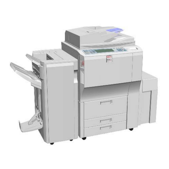
1.2 COPIER AND PERIPHERALS 17, 18 B132I116.WMF This is a list of the peripheral devices that can be installed with the copier. Model Name Comments B132/B200 Copier Main machine B756 Copy Tray Attached to main machine B473 Large capacity tray... -
Page 53: Accessories
COPIER B132/B200 1.3 COPIER B132/B200 1.3.1 ACCESSORIES Check the accessories and their quantities against this list. Description Q’ty 1. Instructions Pocket .............. 1 2. Exposure glass cloth holder..........1 3. Exposure glass cloth............1 4. Leveling Shoes ..............4 5. PCU stand ................1 6. -
Page 54: Installation
COPIER B132/B200 1.3.2 INSTALLATION Tapes and packing material B132I703.WMF B132I004.WMF WARNING! Always turn the machine off and disconnect the machine power cord before you do these procedures. Remove all tapes and packing material from the outside of the main machine:... - Page 55 COPIER B132/B200 B132I002.WMF [A]: Under ARDF [B]: Operation panel film B132/B200...
- Page 56 COPIER B132/B200 B132I005.WMF 1. Open the front door and, and remove the transfer belt release lever [A](1 tape). We will install this in the correct location later. IMPORTANT! • D [B], [C], O NOT TOUCH AT THIS TIME HESE ITEMS ARE REMOVED AFTER YOU REMOVE THE FACEPLATE •...
- Page 57 COPIER B132/B200 B132I102.WMF 2. From Tray 1 remove: [A]: Block, tape [B]: Retainer, tag, wire ( x1) 3. Remove all retainers and accessories from Trays 2, Tray 3. 1-11 B132/B200...
-
Page 58: Shipping Retainer Removal
COPIER B132/B200 Shipping Retainer Removal B132I006A.WMF 1. Prepare an open space on the floor for the hopper. 2. Remove the screws of the toner hopper cover [A] ( x 3). 3. Put your hands under the left and right corners of the toner hopper, and slowly pull it out on its rails until it stops. - Page 59 COPIER B132/B200 B132I715.WMF B132I902.WMFF 8. Remove the tag, and rod [A] ( x 1). 9. Disconnect the fan connector [B]. 10. Remove the face plate [C] ( x 5). 11. Put the PCU stand [D] on a flat, clean surface.
- Page 60 COPIER B132/B200 B132I723.WMF IMPORTANT! • D O NOT TRY TO PULL OUT THE DRAWER UNIT UNTIL AFTER YOU REMOVE THE FOLLOWING RETAINERS 13. Remove the tape [A]. 14. Pull on the reinforced part [B] on tag [C] to remove the stabilizing rod [D].
-
Page 61: Developer Cartridge Installation
COPIER B132/B200 Developer Cartridge Installation B132I903.WMF B132R214.WMF Important • The OPC drum is exposed on the bottom of the PCU. • Do not put your hand under the PCU when you hold the PCU. • Always use the PCU stand. Do not put the PCU on other surfaces. - Page 62 COPIER B132/B200 B132R210.WMF 5. On the front end of the PCU, remove the shaft cap [A] and lock plate [B] ( x 3). Important: After you remove the shaft cap, make sure that you do not turn the shaft [C] of the development roller.
- Page 63 COPIER B132/B200 B132I105.WMF B132I105A.WMF 8. Place the development unit [A] on a clean sheet of A3/DLT paper [B]. 9. Remove the screws from the dummy cartridge [B] ( x 2). 10. With a fingernail, release the tabs on the left [C] and right [D].
- Page 64 COPIER B132/B200 B132I106.WMF B132I106A.WMF 13. Thread the film seal [A] through hole [B]. 14. Slide the developer cartridge down [C] on the left so the holes and tabs [D] are aligned. 15. Press in on the middle of the developer cartridge [E] to lock the tabs inside [F].
- Page 65 COPIER B132/B200 B132I106B.WMF B132I106C.WMF 17. Check the following to points to be sure that the developer cartridge is set properly. • Tabs [A] and [B] should be locked. • The developer cartridge edge [C] should be flat and not bulging or floating away from the side of the development unit •...
-
Page 66: Reassemble The Pcu
COPIER B132/B200 B132R222.WMF Reassemble the PCU 19. Reattach the development unit to the PCU. IMPORTANT! • H ANDLE THE DEVELOPMENT UNIT CAREFULLY WHEN YOU REATTACH IT TO THE PCU. AVOID DAMAGING THE DRUM INSIDE THE 20. Attach the front and rear lock plates (refer to p. 1-16). - Page 67 COPIER B132/B200 B132I114.WMF 22. Hold the PCU [A] in front of the slot where you removed it. 23. Engage the rails [B] with the slots in the sides of the PCU. 24. Slowly push the PCU into the slot. Make sure the tab [C] above the PCU is locked.
-
Page 68: Reattach The Face Plate
COPIER B132/B200 Reattach the Face Plate B132I716.WMF 1. Attach the face plate [A] with the screws in the sequence shown by the numbers above ( x 5). Important: • Do not tighten these screws too much. • Make sure the fan connector [B] is not pinched behind the face plate. -
Page 69: Remove The Retainers In The Drawer Unit
COPIER B132/B200 Remove the Retainers in the Drawer Unit B132I709.WMF 1. Turn the lever [A] down to the left, and pull the drawer unit [B] out of the machine until it stops. 2. Remove the instruction sheets [C] and [D]. - Page 70 COPIER B132/B200 B132I722.WMF 5. Raise lever D2 [A]. 6. Turn knob D1 [B] in the direction shown by the arrow. 7. Remove protective sheet [C]. 8. Lower lever D2 [A]. 9. Push the drawer into the machine until it stops.
- Page 71 COPIER B132/B200 B132I707.WMF 11. Locate the transfer belt release lever [A]. It was removed earlier with the shipping tape. 12. Attach the transfer belt release lever. 13. Turn it to the vertical position and make sure that it locks. Important: •...
-
Page 72: Reinstall The Toner Hopper
COPIER B132/B200 Reinstall the Toner Hopper " & B132I006.WMF 1. Make sure that the transfer belt release lever [A] is up and locked before you attach the hopper. 2. Pull the toner hopper left rail [B] and right rail [C] until they are fully extended. -
Page 73: Stc (Soft Toner Cartridge) Installation
COPIER B132/B200 STC (Soft Toner Cartridge) Installation Important: • Make sure that you install each STC in the correct bin. • The label on the toner cartridge must face the front of the machine. • From left to right, the bins are for Yellow→ Cyan→ Magenta→ Black. -
Page 74: Make The Machine Level
COPIER B132/B200 Make the Machine Level B132I717.WMF 1. Attach the leveling shoes [A] to the machine. 2. Place a level on the exposure glass. 3. Use a wrench to lift or lower the nuts [B] on the leveling shoes until the machine is less than 5 mm from level (measure it from front to rear and from left to right). -
Page 75: Attach The Pcu Stand Rack
COPIER B132/B200 Attach the PCU Stand Rack B132I718.WMF 1. Hold the PCU stand rack [A] with its open end pointed as shown, and put it below the machine. 2. Attach the rack to the bottom of the machine with the magnets on the rack. -
Page 76: Attach Decals
COPIER B132/B200 Attach Decals Front Set 1. Attach the paper-installation decals to the trays. These tell you how to add new paper. • Front set decal: Attach this decal to the LCT if it is installed. ‘Front set’ Back Set B132I910.BMP... -
Page 77: Initializing Developer And Toner
Rev. 07/2005 COPIER B132/B200 Initializing Developer and Toner 1. At the left rear corner of the machine, make sure that the manual breaker switch [A] is Important: When the breaker switch is UP, the copier is ready to be turned ON. The "|"... - Page 78 COPIER B132/B200 5. Close the front door after "Open Cover" appears on the display. 6. Enter the SP mode and do 3811 001 (Execute Developer Setup). 7. Push [Execute]. Approximately 4 minutes is necessary for this operation. SP3811 001 does these tasks: •...
-
Page 79: Load The Paper Trays
COPIER B132/B200 Load the Paper Trays For each paper cassette tray: 1. Move the side fence and bottom fence to the correct positions for the paper. 2. Add paper to the trays. 3. Attach the paper size decals to the front of the paper cassette trays and the tandem tray. - Page 80 COPIER B132/B200 5. Remove the C-4 test chart from the exposure glass (this was put on the exposure glass during the previous procedure ‘Make a Test Color Print’). 6. Place the color test pattern face-down (this is the test pattern that you made in step 4).
-
Page 81: Counter Display Setting
COPIER B132/B200 Counter Display Setting The default setting for the counter is "0" (development). Do the SP setting below to set the counter for copy/print (paper count). 1. Enter the SP mode. 2. Do SP5045 001 (Counter Display Setting). 3. Select the counter to use:... -
Page 82: Connect The Upper And Lower Tray Heaters
COPIER B132/B200 Connect the Upper and Lower Tray Heaters B132I009.WMF The machine comes from the factory with the tray heaters disconnected. NOTE: Heater connection is optional, but the heaters must be connected if the location has high humidity. Speak with the customer before you connect the tray heaters. -
Page 83: Copy Tray (B756)
5. Small Cap ................4 6. Tapping Screw (M4 x 8)............1 7. Harness Clamp ..............1 8. Paper Height Sensor ............1 9. Actuator Arm Bracket............1 10. Sensor Bracket ..............1 11. Actuator Arm..............1 B756I001.WMF 1-37 B132/B200... -
Page 84: Installation
COPY TRAY (B756) 1.4.2 INSTALLATION B756I101.WMF 1. Remove the left upper cover [A] ( x 2). B132/B200 1-38... - Page 85 3. Attach the sensor bracket and actuator arm bracket [D] to the copier ( x3). 4. Attach the sensor harness [E] ( x1, x4). 5. Attach the actuator [F] to the arms of the actuator arm bracket. 1-39 B132/B200...
- Page 86 6. Reattach the left upper cover [A] ( x2). 7. Attach the tray [B]. 8. Attach the small caps [C] to the holes ", #, $, %. 9. Install the large cap [D] in the finisher power connection point. B132/B200 1-40...
-
Page 87: A3/11" X 17" Paper Size Tray (B331)
A3/11" X 17" PAPER SIZE TRAY (B331) 1.5 A3/11" X 17" PAPER SIZE TRAY (B331) The A3/11" x 17" Paper Size Tray is installed in tray 1 of the B132/B181/B200 copier. 1.5.1 ACCESSORIES Check the accessories and their quantities against this list. -
Page 88: Installation
1. Remove the metal retainer [A] and packing material [B] ( x 1). 2. Check the position of the front and rear fences, and make sure that they are set for DLT or A3. B132/B200 1-42... - Page 89 3. Open the front doors. 4. Pull out the tandem feed tray [A] fully. 5. Push the right tandem tray [B] into the machine. 6. Remove the left tandem tray [C] ( x 2 left, x 3 right). 1-43 B132/B200...
- Page 90 A3/11" X 17" PAPER SIZE TRAY (B331) B331I102.WMF B331I709.WMF 7. From the left tandem tray, remove the front cover [A] ( x 2). 8. Pull out the right tandem tray [B], then remove it. ( x 2). B132/B200 1-44...
- Page 91 Use the screws that you removed in Steps 6 and 8. NOTE: You must use the short, silver screws on the left and right rails. If you use one of the longer screws, it will stop the movement of the tray on the rails. 1-45 B132/B200...
- Page 92 11. Install the front cover [A] ( x 2) that was removed from the left tandem tray. 12. Use SP5959 001 to select the paper size for Tray 1 (A3 or DLT). 13. After you select the paper size, turn the machine off and on to change the indicator on the operation panel. B132/B200 1-46...
-
Page 93: Key Card Bracket (B498), Key Counter Bracket (B452)
1. Key Card Table..............1 2. Harness Clamp ..............1 3. Tapping Screws (M3 x 8)............. 4 4. Tapping Screws (M4 x 14)........... 2 5. Stud ..................1 6. Decal ................... 1 7. Key Card Table Support ............1 B498I001.WMF 1-47 B132/B200... -
Page 94: Key Counter Bracket B452 Accessories
4. Tapping Screws (M3 x 6)............. 2 5. Tapping Screws (M4 x 8)............. 3 6. Tapping Screws (M4 x 16)........... 2 7. Harness ................1 8. Shoulder Screw ..............1 9. Key Counter Bracket Cover ..........1 10. Key Counter Bracket............1 B452I001.WMF B132/B200 1-48... -
Page 95: Installation
1. Hold the key counter plate nuts [A] on the inner surface of the key counter bracket [B]. 2. Attach the key counter holder [C] to the key counter bracket ( x2). 3. Attach the key counter bracket cover [D] ( x2). 1-49 B132/B200... -
Page 96: Install The Key Card Bracket And Assembled Key Counter
4. Attach the stud [D]. 5. Put the keyholes [E] of the key card table [F] over the heads of the shoulder screws, as shown above. Then tighten the screws to attach the table (M4 x 14, x2). B132/B200 1-50... - Page 97 6. Attach the key counter bracket [A] ( x 2). 7. Attach the harness [B] to the key counter bracket and the machine ( x 1). 8. Attach the bracket support [C] to the side of the copier ( x 2). 1-51 B132/B200...
-
Page 98: Lct (B473), Lct Adapter (B699)
Check the accessories and their quantities against this list. LCT (B473) Description 1. Upper docking pins (grooved) ............ 2 2. Lower docking pin (not grooved, not for B132/B181/B200)..1 3. Flat-head shoulder screw - M4x6..........1 4. Paper Set Decal................. 1 B473I101.WMF... -
Page 99: Lct Adapter (B699)
LCT (B473), LCT ADAPTER (B699) LCT Adapter (B699) Description 1. Brackets ................. 2 2. Supports................. 3 3. Machine Screws (M3x8) ............3 4. Machine Screws (M4x8) ............6 B699I101.WMF 1-53 B132/B200... -
Page 100: Installation
1. Remove the filament tape [A]. 2. Remove the decals [B]. 3. Remove the tape under the lid [C]. 4. Remove the docking pins [D] (attached to the rear with tape). 5. Remove the docking pins [E]. B132/B200 1-54... -
Page 101: Lct Adapter (B699) Installation
3. Attach the 3 supports [D] ( x 1 each – M3x8 thin screws). 4. Set the LCT in a vertical position. 5. Remove the stay [E] ( x 4). 6. Attach the stay at [F] ( x 4). 1-55 B132/B200... -
Page 102: Lct Installation
4. Attach the brackets [D] that are supplied with the LCT Adapter (B699) ( x 2 each – M4 x 8). 5. Attach the two grooved docking pins [E]. NOTE: The docking pin without a groove is not necessary for this installation. B132/B200 1-56... - Page 103 8. Slowly push the LCT onto the pins. NOTE: The release button [D] is used to unlock the LCT. 9. Connect the plug [E] of the LCT power connector to the side of the machine. 1-57 B132/B200...
- Page 104 A4 paper. You must select the paper size with this SP. 17. Input "0" for A4 LEF or "4" for 8 " x 11" LEF. 18. Turn the machine off and on to enable the setting. B132/B200 1-58...
-
Page 105: 81/2" X 14"/B4 Paper Size Tray (B474)
1. Tapping screws - M4x8............4 2. Tapping hex screws - M4x8 ........... 6 3. Harness clamp............... 1 4. B4/LG frame ................1 5. Front bracket................1 6. Rear bracket ................1 7. Bottom plate extension ............1 8. Cover ..................1 1-59 B132/B200... -
Page 106: Installation
4. Remove the right stay [C] and attach it below ( x 2). 5. Change the position of the lower limit sensor [D] ( x 1). 6. Attach the harness clamp (not shown) to the rear of the plate. Use this clamp to hold the sensor connector wire. B132/B200 1-60... - Page 107 12. Attach the B4/LG frame [F] with the hex screws ( x 2). B474I553.WMF 13. Move the front side fence [G] and rear side fence [H] to the B4 or 8 " position and attach it ( x 1). B474I555.WMF 1-61 B132/B200...
- Page 108 15. Attach the right cover [B] ( x 2). 16. Connect the LCT to the machine. 17. Turn the machine on. 18. Go into the SP mode. 19. Do SP5959 005. 20. Input “5” for B4 SEF or “6” for 8 " x 14" SEF. B132/B200 1-62...
-
Page 109: 2000/3000 Sheet Finishers (B700/B701)
5. Leveling Shoes ..............3 6. Upper output tray ..............1 7. Lower output tray (B700 Only) ..........1 8. Front joint bracket ..............1 9. Rear joint bracket..............1 10. Gasket Seal ................1 11. Support Plate ................. 1 B700I201.WMF 1-63 B132/B200... -
Page 110: Installation
This section shows the installation instructions for two finishers: • B700 Booklet Finisher: This can do punching, shifting, stapling, and saddle- stitching with staples. This booklet finisher can be used with the B132, B181, or B200. • B701 Finisher, capable of punching, shifting, and stapling but with no saddle- stitching unit. - Page 111 2000/3000 SHEET FINISHERS (B700/B701) B701 B700 B701I202.WMF B700I202.WMF 3. Open the front door. 4. Remove all tapes and packing materials inside the finisher. 1-65 B132/B200...
- Page 112 2000/3000 SHEET FINISHERS (B700/B701) B700 B701 B701I204.WMF B700I204.WMF 5. Pull the jogger unit [A] out of the finisher. 6. Remove the tapes and retainers. B132/B200 1-66...
-
Page 113: Docking The Finisher To The Copier
• Install the interposer on the finisher before you dock the finisher to the copier. (!1.15: do the complete procedure.) Then come back to the procedure for the B700/B701 finisher, and continue from ‘Attaching the Trays’. 1-67 B132/B200... - Page 114 2000/3000 SHEET FINISHERS (B700/B701) B700I105.WMF 2. Attach the rear bracket [A] ( x 2, M4 x 14). 3. Attach the front bracket [B] ( x 2, M4 x 14). B132/B200 1-68...
- Page 115 7. Connect finisher connector [E] to the main frame. 8. Attach the gasket seal [F] as shown. " Important! Check the duct on the left side of the machine. Make sure that the sponge does not block this duct. " B132R734.WMF 1-69 B132/B200...
-
Page 116: Attaching The Trays
NOTE: Make sure that the metal plate [B] is on the top of the tray. 2. Attach the lower output tray [C]. B701 1. Attach the output tray [A]. NOTE: Make sure that the metal plate [B] is on the top of the tray. B132/B200 1-70... -
Page 117: Leveling The Finisher
2000/3000 SHEET FINISHERS (B700/B701) Leveling the Finisher B701I109.WMF 1. Put the leveling shoes [A] (x 3) below the feet [B]. 2. Use a wrench to adjust the height of the screws [C] to make the machine level. 1-71 B132/B200... -
Page 118: Support Tray
2. If Step 1 does not solve the problem, place the support tray [B] on the exit tray with the >PP< mark positioned as shown at [C]. 3. If Step 2 does not solve the problem, place the support tray on the exit tray with the >PP< mark positioned as shown at [D]. B132/B200 1-72... -
Page 119: Selecting The Staple Supply Name
4. Touch a “Stapling Position” button and touch the center (saddle-stitch) stapling symbol. 5. Go out from the User Tools mode. Set the number of copies, touch the center stapling symbol on the operation panel, then start the print job. 1-73 B132/B200... -
Page 120: Punch Unit (B702)
3. Punch Waste Hopper............1 4. Screws (M3 x 6)..............5 5. Side-to-Side Detection Unit ..........1 6. Punching Unit ..............1 B702I101.WMF WARNING! Always turn the machine off and disconnect the machine power cord before you do this procedure. B132/B200 1-74... -
Page 121: Installation
5. Connect and attach the punch unit [E] ( x 2, x 1). • The cables [F] are coiled and attached to the PCB. • Attach connectors to CN601 and CN602. 1-75 B132/B200... - Page 122 10. Attach the side-to-side detection unit and connect it at the rear ( x 2, x 1, x 1). 11. Pull the short connector out of the connector [C] then connect the cable ( x NOTE: This is the 3-pin connector. B132/B200 1-76...
- Page 123 14. Remove the short connector from the connector [C]. NOTE: This is the 4-pin connector. 15. Connect the cable and attach the punch-waste transport unit ( x 1, x 1, x 1). 16. Set the hopper [D] in its holder. 1-77 B132/B200...
-
Page 124: Mail Box (B762)
The Mail Box B762 is installed on the 2000/3000 Sheet Finisher B700/B701. 1.11.1 ACCESSORIES Check the accessories and their quantities against this list. Description 1. Trays..................9 2. Guide plate ................1 3. Decals (bin display) ............... 1 4. Tapping screws - M3x8............6 B132/B200 1-78... -
Page 125: Installation
Turn the machine off and disconnect the machine power cord before you start this procedure. 1. Remove the filament tape [A]. Important: Move the mailbox carefully. It is easy to cause damage to the corner leaf plate [B]. 1-79 B132/B200... - Page 126 2. If the Cover Interposer Tray B704 is installed on the B700/B701, remove it. NOTE: The cover interposer tray and mailbox cannot be installed on the finisher at the same time. 3. Remove the top cover [A] of the finisher ( x1). 4. Remove the bracket [B] ( x1). B132/B200 1-80...
- Page 127 6. Attach the mailbox [B] to the top of the finisher ( x4, M3x8). 7. Attach the 9 trays [C] to the mailbox. 8. Give the decals [D] to the customer. The customer will write on these and attach them at the correct location. 1-81 B132/B200...
-
Page 128: 3000-Sheet Finisher (B706), Finisher Adapter (B698)
6. Ground (Earth) Plate.............. 1 7. Tray Holder (Not used for B132/B181/B200) ......1 8. Auxiliary Tray (Proof Tray) (Not used for B132/B181/B200) .. 1 9. Auxiliary Tray (Shift Tray) (Not used for B132/B181/B200) ... 1 10. Phillips Screws w/washer - M4 x 14........4 11. -
Page 129: Finisher Adapter Kit B698 Accessories
1. Upper Transport Motor Bracket ..........1 2. Timing Belt................1 3. Short Connector..............1 4. Harness ................. 1 5. Gasket Seal ................1 6. EPROM ................. 1 7. Harness Clamps ..............2 8. Serial Number Seal..............1 B698I101.WMF 1-83 B132/B200... -
Page 130: Installation
3000-SHEET FINISHER (B706), FINISHER ADAPTER (B698) 1.12.2 INSTALLATION WARNING! Turn the machine off and disconnect the machine power cord before you do this procedure. Shipping tape and retainers B706I002.WMF 1. Remove the finisher from its box. Remove all tapes and packing materials. B132/B200 1-84... - Page 131 2. Open the front door [A] and remove tape and packing materials. 3. Pull the jogger unit [B] out of the finisher. 4. Remove brackets [C], [D], and [E] ( x 2 each) with their red tags and wires, and all tapes and packing materials. 1-85 B132/B200...
-
Page 132: Finisher Adapter Kit B698 Installation
B698I102.WMF B698I103.WMF 1. Remove the finisher rear cover [A] ( x2). 2. Connect the short connector [B] to CN137 on the finisher main board. 3. Remove the upper transport motor mount [C] ( x1, x3, spring x1). B132/B200 1-86... - Page 133 5. Set the motor on the new bracket [C] supplied with the Finisher Adapter Kit B698. 6. Attach the timing belt [D]. 7. Use the same screws to attach the transport motor to the new bracket ( x4). 1-87 B132/B200...
- Page 134 • The harness [D] is supplied with the Finisher Adapter B698. • Attach the screws but do not tighten. Pull the spring slightly to apply tension, then tighten the screws. 11. Remove EPROM [E] and replace it with EPROM [F] that is supplied with the Finisher Adapter B698. B132/B200 1-88...
- Page 135 14. Make sure that the harnesses do not touch the motor. 15. Attach the finisher rear cover. 16. Open the front door. Attach the serial number decal [C] below the finisher- serial-number [D] decal that is attached to the front, bottom support of the finisher frame. 1-89 B132/B200...
-
Page 136: Finisher Installation
3. Remove the connector cover [C]. 4. Attach the grounding plate [E] ( x 2) (M3 x 6). Important: Set the grounding plate so there is no gap [E] between the grounding plate and the bottom frame of the finisher. B132/B200 1-90... - Page 137 • Do not attach the entrance guide plate [D] to the finisher. • Install the interposer before you dock the finisher to the copier. Then come back to the procedure for the B706 finisher, and continue from ‘Selecting the Staple Supply Name’. 1-91 B132/B200...
- Page 138 14. Use a wrench to adjust the height of the feet [G] to make the machine level. 15. Push in the lock lever [D], attach it ( x 1), then close the front door. 16. Connect the finisher cable [H] to the copier. B132/B200 1-92...
-
Page 139: Selecting The Staple Supply Name
These names show when the user prints the Inquiry List. To print this list push User Tools> [Inquiry]> [Print Inquiry List]> [Start]. 012 Staple Std Input the name of the staples that are used for corner stapling. This setting should be done for the B706 with B698. 1-93 B132/B200... -
Page 140: Punch Unit B531/A821
6. Spring ..................1 7. Step Screw (large) (M4 x 11) ............. 1 8. Tapping Screw (M4 x 10)............2 9. Step Screw (small) (M3 x 4)............1 10. Machine Screw, Washer (M4 x 6)..........1 11. Knob ..................1 B531I001.WMF B132/B200 1-94... -
Page 141: Installation
4. Remove the inner cover [C] ( x 3). 5. Behind the inner cover at [D] and [E], push the lock tabs to the right to release the inner cover from the frame. 6. Remove the plastic sections [F] from the cover. 1-95 B132/B200... - Page 142 7. Remove the paper guide [A] ( x 4). 8. Install the sensor arm [B] ( x 1, small step screw (M3 x 4). NOTE: Make sure that the sensor arm turns freely on the step screw. 9. Attach the spring [C]. B132/B200 1-96...
- Page 143 These two spacers are used to adjust the horizontal position of the punch holes. 13. At the front, attach the punch unit knob [E] ( x 1). 1-97 B132/B200...
- Page 144 17. Put the hopper [F] in the finisher. 18. Attach the inner cover and rear cover. 19. Close the front door and connect the finisher to the machine. B132/B200 1-98...
-
Page 145: Output Jogger Unit (B703/B513)
Check the accessories and their quantities against this list. Description 1. Jogger Unit ..................1 2. Tapping Screws - M3 x 6 ............... 2 B703I101.WMF WARNING! Always turn the machine off and disconnect the machine power cord before you do this procedure. 1-99 B132/B200... -
Page 146: Installation
1. Turn the main machine switch off. 2. Disconnect the finisher from the main frame. 3. Use the flat head of a screwdriver to remove the left upper cover [A]. 4. Remove the cover plate [B] ( x 2). Keep the screws. B132/B200 1-100... - Page 147 [A] into the holes in the left and right side of the finisher frame. 6. Fasten connector [B] to the socket ( x 1). 7. Attach the jogger unit to the finisher ( x 2). 8. Reattach the jogger unit cover [C] to the jogger unit ( x 2). 1-101 B132/B200...
- Page 148 11. Right Rear Cover Plate (B706 only) ........1 12. Anti-Static Brush..............1 13. Spacer (B706 only) ..............1 14. Spacer* (B468/B469 only)............ 1 15. Right front corner plate (for B706) only)......... 2 16. Front door extension (bottom) ..........1 B704I101.WMF B132/B200 1-102...
-
Page 149: Cover Interposer Tray (B704)
Reattach them just before docking the finisher to the copier. 2. Remove all tape and retainers from the cover interposer tray [A]. 3. Remove the tape and packing material [B] from the ground connector. 1-103 B132/B200... -
Page 150: Preparing The Finisher (B700/B701/B706)
Go to "Attaching the Extensions for the B700/B701" on page 1- 108. -or- If you will install the B706, modify the extensions and attach them to the finisher. Go to "Attaching the Extensions for the B706" on page 1-105. B132/B200 1-104... -
Page 151: Attaching The Extensions For The B706
3. Remove [D] and replace it with [E] ( x 1). 4. Remove [F] and replace it with [G] ( x 1). Plate Extension (Bottom): 5. Remove bracket [H] and attach it to the end of the bottom plate extension ( x 2). 1-105 B132/B200... - Page 152 3. Remove the screws from the connector casing [C] ( x2). 4. Push the connector casing in the direction of the arrow until the second set of holes is aligned with the holes below, then attach the screws. B132/B200 1-106...
- Page 153 7. Attach the rear cover extension [F] to the finisher ( x 2, M3 x 6). 8. Push up the bottom of the rear cover extension to close the gap at the top of the cover, then tighten the screws. 1-107 B132/B200...
-
Page 154: Attaching The Extensions For The B700/B701
4. Attach the bottom front cover extension [D] ( x 2, M4 x 8). 5. Attach the top front cover extension [E] ( x 2, M4 x 8). 6. Attach the rear cover extension [F] ( x 2, M3 x 6). B132/B200 1-108... -
Page 155: Attaching The Interposer Tray (B700/B701/B706)
Go directly to “Docking Finisher/Interposer” on page 1-112. -or- If you will install the cover interposer tray on the B706, go to the next section, install the corner plates on the B706, then go to “Docking Finisher/Interposer” on page 1-112. 1-109 B132/B200... -
Page 156: Attaching The Corner Plates For The B706
2. Align the notches [C] in the right rear corner plate [D] with the screws and attach the plate. 3. Put a long screwdriver through the notches in the right rear corner plate [D]. Then, tighten the screws to attach the right rear corner plate to the table extension [B]. B132/B200 1-110... - Page 157 You will hear a click when it is in the correct position. 6. Put a long screwdriver in the notch [C], and tighten the screw to attach the right front corner plate. 1-111 B132/B200...
-
Page 158: Docking Finisher/Interposer With The Machine (B700/B701/B706)
COVER INTERPOSER TRAY (B704) Docking Finisher/Interposer with the Machine (B700/B701/B706) B704I121.WMF 1. Attach the rear bracket [A] ( x 2, M4 x14). 2. Attach the front bracket [B] ( x 2, M4 x14). 3. Attach the gasket seals [C] and [D]. B132/B200 1-112... - Page 159 9. Attach the lock lever [D] ( x 1). 10. Connect the connector [G] to the copier. Important! Check the duct on the left side of the machine. Make sure that the sponge does not prevent air flow through this duct. B132I734.WMF 1-113 B132/B200...
-
Page 160: Mfp Controller Options
Applications (1 or several applications combined on 1 SD Card). System Controller SD Card. Never remove! Important! • Only one SD Card slot (Slot 2) is available for applications. To install more than one application, they must be copied on the same SD Card. (%1.16.5) B132/B200 1-114... -
Page 161: Accessory Cards
(, ), *, +, Note: Items must be in the same slot. Because of this, only one of these cards can be installed at the same time. Important! • The B181 is supplied with the printer/scanner kit installed at the factory. 1-115 B132/B200... -
Page 162: Applications Provided On Sd Cards
• Slot 2 holds the application SD card. It also holds the target SD card when applications are put together on one card. • Slot 3 (the top slot) is used to update the machine firmware. It also holds the source SD card when applications are put together on one card. B132/B200 1-116... -
Page 163: Handling Dimms And Sd Cards
2. To remove an SD card, push the SD card in carefully to release it, and then remove it from the slot. Important: To prevent damage to the SD card or the slot lock, always push the card in, to release it, before you try to remove it. 1-117 B132/B200... -
Page 164: Merging Applications On One Sd Card
SD card to the PS SD card. • If an SD card was used to combine applications on that card, that SD card cannot be used for a different function. • N SD C EVER REMOVE THE YSTEM ARD FROM B132/B200 1-118... -
Page 165: Merging Applications
• The original card can also be used to perform an undo procedure (SP 5873 002). Before you put the card in the front cover, label it carefully so that you can identify it easily if you need to do the undo procedure (see the next page). 1-119 B132/B200... -
Page 166: Undo Exec
5. Go into the SP mode and do SP5873-002 (Undo Exec) 6. Follow the messages on the operation panel to complete the procedure. 7. Turn the main switch OFF. 8. Remove the SD cards from the slots. 9. Turn the main switch ON. B132/B200 1-120... -
Page 167: Storing Sd Application Cards On Site
Storing SD Application Cards on Site B132I728.WMF 1. Open the front door. 2. Remove the cover [A] on the door ( x2). 3. Remove the block [B]. 4. Store the SD cards [C] inside the cover. 5. Attach the cover to the machine. 1-121 B132/B200... -
Page 168: Printer/Scanner B737 And Interface Unit
3. NIB ..................1 4. Screws - M3x8............... 2 5. Ferrite Core ................1 6. Key Top Assembly ..............1 7. Operating Instructions – Printer..........1 8. Installation Instructions............1 9. FCC Label ................1 10. Software CD-ROM ..............3 B132/B200 1-122... -
Page 169: Installation
6. Install the Interface Unit Board [D] (NIC/USB) B763 in Slot E. 7. Remove the SD card slot cover [E] ( x2) 8. Install the Printer/Scanner SD card [F] in SD Card Slot 2 (middle slot). 9. Attach the SD card slot cover ( x2). 1-123 B132/B200... - Page 170 15. Do the procedures in the operating instructions to make the user settings (for example, the IP address). B737I115.WMF 16. Do the color calibration for the printer: User Tools> Maintenance> Auto Color Calibration> Printer Function: Do all three test patterns. B132/B200 1-124...
-
Page 171: Usb Sp Settings
High speed/Full speed auto adjust (480Mbps/12Mbps) Full speed (12Mbps fixed) 5844 002 Vendor ID Displays the vendor ID. DFU 5844 003 Product ID Displays the product ID. DFU 5844 004 Dev. Release Num Displays the development release version number. DFU 1-125 B132/B200... -
Page 172: Ieee 1284 Interface Board B679 (Centronics)
3. Put the interface board [B] in Slot D and attach it ( x2). 4. Turn the machine off and on. Then do SP5990 to print an SMC Report to check that the interface board is installed correctly. B132/B200 1-126... -
Page 173: Ieee 1394 Interface Board B581 (Firewire)
3. Put the interface board [B] in Slot D and attach it ( x2). 4. Turn the machine off and on. Then do SP5990 to print an SMC Report to check that the interface board is installed correctly. 1-127 B132/B200... -
Page 174: Up Mode Settings For Ieee 1394
IP Over 1394 as the default setting for the printing method. • SCSI Print. Enable or disable this setting as necessary. This setting enables SCSI Print as the default setting for the printing method. • SCSI Print Bi-directional. Switch bi-directional printing on or off for SCSI print. B132/B200 1-128... -
Page 175: Sp Mode Settings For Ieee 1394
Determines how successive initiator login requests are handled during login for SBP-2. 5839 012 Login Enables or disables exclusive login for SBP-2. 5839 013 Login MAX Sets the limit for the number of logins for SBP-2. Range: 1 ~ 62. 1-129 B132/B200... -
Page 176: Bluetooth Interface Unit B736-11
Check the quantity and condition of the accessories. Description Q’ty Bluetooth card Bluetooth card cover Bluetooth board Only one PCI slot is available for one of these options: • IEEE 801.11b (Wireless LAN) • IEEE 1394 (FireWire) • IEEE 1284 • Bluetooth B132/B200 1-130... -
Page 177: Installation Procedure
6. Push the antenna cap [D] to extend it. 7. Attach the card cover [E] (used to prevent static electricity). 8. Turn the machine off and on. Then do SP5990 to print an SMC Report to check that the interface board is installed correctly. 1-131 B132/B200... -
Page 178: Ieee 802.11B Interface Unit G813-04, -05
Only one interface slot is available for one of these options. Because of this, only one board can be installed at the same time: • IEEE 1284 Interface Board B679 (Centronics) • IEEE 1394 Interface Board B581 (FireWire) • Bluetooth Interface Board B763 • IEEE 802.11b Interface Unit B736 (Wireless LAN) B132/B200 1-132... -
Page 179: Installation
5. Remove the cap [C] and discard it. 6. Put the card [D] in the slot of the interface card. 7. Turn the machine off and on. Then do SP5990 to print an SMC Report to check that the interface board is installed correctly. 1-133 B132/B200... -
Page 180: Up Mode Settings For Wireless Lan
In order to unlock encoded data, the same WEP key is required on the receiving side. There are 64 bit and 128 bit WEP keys. Range of Allowed Settings: 64 bit 10 characters 128 bit 26 characters B132/B200 1-134... - Page 181 1 Mbps 400 m (437 yd.) 12. To initialize the wireless LAN settings, use page 2/2. Press Execute to initialize the following settings: • Transmission mode • Channel • Transmission Speed • WEP • SSID • WEP Key 1-135 B132/B200...
-
Page 182: Sp Mode Settings For 802.11B Wireless Lan
Used to confirm the current WEP key setting. 5840 011 WEP Key Select Used to select the WEP key (Default: 00). 5840 020 WEP Mode Used to display the maximum length of the string that can be used for the WEP Key entry. B132/B200 1-136... -
Page 183: File Format Converter B609
4. Check that the board is fully in the slot, then attach it ( x2). 5. Turn the machine off and on. Then do SP5990 to print an SMC Report to check that the interface board is installed correctly. 1-137 B132/B200... -
Page 184: Postscript3 B761
PostScript3 SD card cannot be copied for copyright reasons. • After you copy the printer/scanner SD card, store it behind the door. (%Pg.1-121) The application SD cards are the property of the customer and should remain at the site. B132/B200 1-138... -
Page 185: Dos Unit Type C (B735)
Also, the DOS card application can be copied to the scanner/printer card. After you copy the printer/scanner SD card or DOS card, store it behind the door. (%Pg.1-121). The application SD cards are the property of the customer and should remain at the site. 1-139 B132/B200... -
Page 186: Seal Check And Removal
4. Copy the DOS card to another application’s SD card (for example, the printer/scanner or PostScript card). 5. After you copy the DOS card, store it behind the door. Use the combined DOS/other application SD card for the next part of the installation procedure. B132/B200 1-140... -
Page 187: Installation Procedure
3. Remove the slot cover [A] ( x 2). 4. Install the SD Card [B] into slot 2, then attach the slot cover. 5. Connect the network cable (if the machine is connected to a network). 6. Turn the main power switch on. B132I909.WMF 1-141 B132/B200... - Page 188 • “Next Copy” is shown for a short interval below the icon. • The icon goes back to its usual shape [C]. 15. Remove the Document Server and Scanner key-tops, and replace them with the blank key-tops that are supplied with the kit. B132/B200 1-142...
-
Page 189: Copier Connection Kit B328
2. Remove the cover [A] of Slot B ( x 2). 3. Install the Copier Connection Kit Board B328 [B] in Slot B and attach it with the screws. 4. Remove the rear upper cover. (%See 3.3.6) 1-143 B132/B200... - Page 190 -or- Attach the "Other Function" key [G] (or its equivalent symbol for EU) if the printer/scanner option is not installed. 13. Attach the other end of the connection cable to the connection PCB installed in the other machine. B132/B200 1-144...
-
Page 191: Efi V G815 External Controller
1.16.15 EFI V G815 EXTERNAL CONTROLLER B737I905.WMF 1. Turn the machine off. 2. Remove the cover [A] of Slot C ( x 2). 3. Install the EFI-V G815 board [B] in Slot C and attach it with the screws. 1-145 B132/B200... -
Page 193: Preventive Maintenance
PREVENTIVE MAINTENANCE... -
Page 195: Preventive Maintenance
Important • The Lubricant Powder (B1329700) (composed of Zinc Stearate) is specially designed for this machine (B132/B181/B200). If this lubricant powder is not available, please use this machine’s yellow toner. • Always use this lubricant powder to lubricate the drum and ITB during servicing. -
Page 196: Pm Counter
"Yes". (!Pg.2-4) Clear all PM settings. Resets all PM counter settings to "0" at the same time. PM items can be reset one by one with the [Clear] button. (!Pg.2-4) Counter list print out. Prints the PM counter on paper. B132/B200... -
Page 197: Pm Parts Screen Details
[C]: PM yield buttons. Function is the same as the "PM yield indicator settings" button. (!Pg.2-4). [D]: Current PM counter value. [E]: Target PM interval. This can be changed by pressing a number button [A]. [F]: PM counter clear button. Function is the same as the [Clear current counter] button. B132/B200... -
Page 198: Number Button Submenu
• Latest 1. The latest PM count since the unit (or part) was replaced. • Latest 2. The previous PM count since the unit (or part) was replaced. • Latest 3. The previous but one PM count since the unit (or part) was replaced. B132/B200... -
Page 199: Parts List For Pm Yield Indicator
• The # mark denotes a unit. • Items without the # (065 ITB) denote individual components. • An asterisk & will appear in the Exceed column [A] to show items that that have exceeded their target PM yields. B132/B200... -
Page 200: Pm Tables
Optical cloth 2nd Mirror Optical cloth 3rd Mirror Optical cloth Scanner Rails Alcohol then dry cloth Exposure Glass Exposure glass cleaner Toner Shield Glass Optical cloth APS Sensor Dry cloth ARDF Exposure Glass Exposure glass cleaner Dust Filters Blow brush B132/B200... - Page 201 Alcohol then dry cloth ITB Cleaning Roller ITB Cleaning Scraper Blade ITB Cleaning Blade 150K 300K 600K Note PTR UNIT Paper Transfer Cleaning Blade Paper Transfer Cleaning Brush Roller Paper Transfer Lubricant Bar Paper Transfer Discharge Plate PTR (Paper Transfer Roller) B132/B200...
- Page 202 Dry cloth Registration Sensor Blower brush Vertical Transport Roller Blower brush Sensors LCT Relay Sensor Blower brush Bypass Feed Sensor Blower brush Bypass Paper End Sensor Blower brush Double-Feed Sensor 1 Blower brush (Receptor) Double-Feed Sensor 2 (LED) Blower brush B132/B200...
- Page 203 Inverter Roller Dry cloth 150K 300K 600K Note PAPER EXIT Heat Dissipation Roller Alcohol, dry cloth Exit Anti-Static Brush Inspect, replace if deformed. Paper Exit Rollers (Upper, Lower) Alcohol, dry cloth Paper Exit Sensor Blower brush Transport Rollers Blower brush B132/B200...
-
Page 204: Ardf Pm Parts
Upper Inverter Sensor White Cover Alcohol or water, dry cloth Transport Belt Feed Drive Gears G501 Grease Grip Roller Alcohol or water, dry cloth Transport Rollers Scanner Rollers (Entrance/Exit) Exit Rollers Inverter Rollers (Lower, Exit, Upper) Idle Rollers B132/B200 2-10... -
Page 205: Sheet Booklet Finisher B700/B701
Shaft Bearings Lubricate with silicone oil if noisy. Sensors Blower brush. Jogger fences Make sure that the screws are tight. Staple waste hopper Empty staple waste. PUNCH B531/A821 EM 300K 450K 600K Note Punch Waste Hopper Remove and empty 2-11 B132/B200... -
Page 206: Cover Interposer Tray B704
Separation Roller Driver Rollers Damp clean cloth. Idle Rollers Discharge Brush Sensors Blower brush. 2.3.6 LCT B473 1000K 2000K 3000K Expected Note Paper feed roller Pick-up roller Separation roller Transport guide plate Inspect and clean every 350K. Grip roller B132/B200 2-12... -
Page 207: Lubrication Points
LUBRICATION POINTS 2.4 LUBRICATION POINTS 2.4.1 COPIER OPC, ITB Replacement B132R319.WMF B023R960.WMF Be sure to apply Lubricant Powder B1329700 when re-installing the drum[A] or ITB [B]. For more, please refer to section "3. Replacement and Adjustment". 2-13 B132/B200... -
Page 208: Fusing Unit
Brush all gear teeth Upper Gear Lower Gear Bearing Race φ20 x φ32 x 7 Barrierta S552R Hot Roller Sleeve Be sure to brush both ends. Bearing Race φ25 x φ37 x 7 Hot Roller Sleeve Bearing Race B132/B200 2-14... -
Page 209: Replacement And Adjustment
REPLACEMENT AND ADJUSTMENT... -
Page 211: General Cautions
3. To prevent drum scratches, always set the PCU on the stand and leave it there as long as it is out of the machine. 4. Remove only one PCU at a time for servicing. Only one PCU stand is provided with the machine. B132/B200... -
Page 212: Transfer Belt Unit
2. Never adjust the variable resistors on the LD unit, as they are adjusted in the factory. 3. Never open the optical housing unit. The polygon mirror and lenses are sensitive to dust. 4. Never touch the glass surface of the polygon mirror motor unit with bare hands. B132/B200... -
Page 213: Development
• After you replace developer (only initialize the TD sensor for the colour that you replaced) • As instructed in specific troubleshooting procedures. If you do not obey the above instructions, you will get toner scattering inside the machine. B132/B200... -
Page 214: Cleaning
3.1.10 USED TONER 1. We recommend checking the amount of used toner at every EM. 2. Always dispose of used toner in accordance with local regulations. 3. Never throw toner into an open flame. B132/B200... -
Page 215: Common Removal Procedures
3. Remove the left screw [B] and right screw [C]. 4. Slide the ARDF back until the heads of the screws are in the large end of the keyholes, then lift the ARDF off the machine. CAUTION The ARDF is very heavy. Remove it carefully. B132/B200... -
Page 216: Operation Panel, Top Covers
• Remove the ARDF ( x1, x2). • Open the front door. Remove: [A]: Operation panel ( x1, x2) [B]: Top rear cover ( x2) [C]: Left top cover ( x1) [D]: Right top cover ( x1) B132/B200... -
Page 217: Left Covers
• If a finisher is connected, disconnect it. Then remove the front and back finisher connection brackets. Remove: [A]: Left upper cover ( x2) [B]: Left lower cover ( x5) Reinstallation • Make sure all the cover tabs are inserted correctly before you fasten the screws. B132/B200... -
Page 218: Front Door
3. Lift the front door slightly to remove it. Important: If you must replace the front door, make sure that you put the SD cards from the storage location in the old front door into the storage location in the new front door. (! 3.2.12) B132/B200... -
Page 219: Right Covers
[D]: Right lower cover ( x5). Pull the bottom of the cover down and toward you as you remove it. Reinstallation • Make sure all the cover tabs are inserted correctly before you fasten the screws. B132/B200... -
Page 220: Rear Covers
COMMON REMOVAL PROCEDURES 3.2.6 REAR COVERS B132R705.WMF Remove: [A]: ARDF connector ( x1) [B]: Rear upper cover ( x3) [C]: Rear lower cover ( x2) • Remove the bottom screws • Do not remove the shoulder screws. B132/B200 3-10... -
Page 221: Toner Hopper, Faceplate, Pcu
CAUTION The hopper is heavy! Lift it carefully, make sure that it disengages completely from the rails on the left and right, and then set it on the floor. 7. Push the hopper rails into the machine. 3-11 B132/B200... - Page 222 11. Place the PCU stand [D] on a flat surface. NOTE: The PCU stand is mounted on a rack attached to the bottom of the copier with magnets. 12. Wipe the surface of the stand with a clean cloth to remove dust. B132/B200 3-12...
- Page 223 PCU. 13. While pressing down the release tab [A] above the PCU, pull the PCU [B] out of the machine. 3-13 B132/B200...
- Page 224 EVER PLACE YOUR HAND UNDER THE • N EVER PLACE THE ON ANY SURFACE OTHER THAN THE STAND 14. Set the PCU [A] on the PCU stand [B]. NOTE: In the diagram, F is the front, and R is the rear. B132/B200 3-14...
-
Page 225: Reinstalling Pcu, Faceplate, Toner Hopper
• To release the developer into the PCU, pull out the film seal [D]. NOTE: Put your other hand on the PCU [E] to keep it stable it while you pull on the film seal. B132I101.WMF 3-15 B132/B200... - Page 226 1. When you reattach the face plate [A] , fasten the screws in the order shown by the numbers above ( x5). Important: Do not over tighten these screws. 2. Rotate the transfer belt release lever [B] clockwise to lock it. 3. Reconnect the fan connector [C] ( x1). B132/B200 3-16...
- Page 227 NOTE: If the toner hopper [B] is not flat against the face plate on the right side, pull it out slightly and make sure that the transfer belt release lever is rotated up completely and locked. 7. Fasten the toner hopper to the face plate ( x3). 3-17 B132/B200...
-
Page 228: Image Transfer Unit
4. Rotate the transfer belt release lever [A] down to the left until it stops. 5. Remove the faceplate [B] ( x1, x5). 6. Rotate the lever B2 [C] on the drawer unit counter-clockwise to separate the transfer roller from the ITB. B132/B200 3-18... - Page 229 • Re-insert the image transfer unit slowly and carefully to avoid snagging the belt on the frame of the machine. • Make sure that the image transfer unit does not snag on the toner cap of the yellow PCU on the far left. 3-19 B132/B200...
-
Page 230: Drawer Unit
4. Disconnect the left rail [C] ( x2). 5. Disconnect the right rail [D] ( x2). 6. Lift the unit off the rails. CAUTION The drawer unit is very heavy (30 kg/66lb.). After removing it, push the rails into the machine. B132/B200 3-20... - Page 231 7. Fasten the screws to the left rail [B] ( x2). 8. Fasten the screws to the right rail [C] ( x2). Important! Make sure these screws are fastened and tight. This ensures that the unit is positioned correctly. 3-21 B132/B200...
-
Page 232: Duplex Unit
3. Remove the Teflon ring [B] from the left, rear corner ( x1). 4. Remove the Teflon ring [C] from the right, rear corner ( x1). 5. Lift the duplex unit from the rails and place it on a flat, level surface. B132/B200 3-22... -
Page 233: Opening And Locking The Controller Box Cover
[D] is touching the machine frame. 6. Reattach the screw removed in Step 4 to lock the arm in position. Reinstallation • Be sure to reattach the stopper arm at its original position before you close the controller box. 3-23 B132/B200... -
Page 234: Sd Card Storage
• When you replace the door, confirm whether SD cards are stored here. • Remove any SD cards and store them in the new door. These SD cards serve as prove of purchase of MFP options by the customer. B132/B200 3-24... -
Page 235: Scanner Unit
SCANNER UNIT 3.3 SCANNER UNIT 3.3.1 EXPOSURE GLASS B132R128.WMF Remove: [A]: Rear scale ( x3) [B]: Left glass cover ( x3) [C]: Exposure glass 3-25 B132/B200... -
Page 236: Lens Block, Paper Size Sensors
• Do the copies have background? • Is the copy output of the ARDF and platen mode different? If these problems occur, change SP4800 001 to 003 to their previous settings, or adjust these SPs until the background is acceptable. B132/B200 3-26... -
Page 237: Exposure Lamp
2. Remove the exposure lamp [B] ( x1, x1, x1) Important: • Never touch the surface of the exposure lamp with bare fingers. • Work carefully to avoid damaging the relay plugs attached to the rear ends of the lamp. 3-27 B132/B200... -
Page 238: Scanner Motor
• Exposure glass (!3.3.1) [A]: Lens cover ( x4) [B]: Right lens cover ( x3) [C]: Top right cover ( x1) B132R133.WMF [D]: Bracket ( x5) [E]: Scanner motor (Timing belt x1, x1, x1, x3) B132/B200 3-28... -
Page 239: Scanner Hp Sensor
• ARDF (!3.2.1) • Exposure glass (!3.3.1) • Top rear, left, right covers (!3.2.5) [A]: Ground plate ( x1) [B]: Left stay ( x3) [C]: Right stay ( x5) [D]: Rear stay ( x4) [E]: Scanner HP sensor ( x1) 3-29 B132/B200... -
Page 240: Scanner Interface Board (Siob)
3.3.6 SCANNER INTERFACE BOARD (SIOB) B132R133A.WMF Remove: • ARDF (!3.2.1) • Exposure glass (!3.3.1) • Top, rear, left, right covers (!3.2.5) • Right stay, rear stay (!3.3.5) • Lens cover (!3.3.2) [A]: Scanner interface board ( x6, x2) B132/B200 3-30... -
Page 241: Scanner Wire
4. Loosen the screw of tension bracket 1. 5. Disconnect the end of wire at 6. Remove lock bracket of the 1st scanner ( x1). 7. Disconnect the wire from the pulley ( x1). 8. Remove the wire from the scanner. 3-31 B132/B200... -
Page 242: Scanner Wire Reinstallation And Scanner Position Adjustment
1. Place the beads [A] on the middle of the wire on the pulley openings. 2. Wind the ball end of the wire [B] 4 times. 3. Wind the other end of the wire [C] 5 times. 4. Attach tape [D] across the pulley to temporarily hold the wires in place. B132/B200 3-32... - Page 243 9. Attach the pulley and tighten it lock screw (!+,Pg. 3.3.7). 10. Remove the positioning pins (x4). 11. Remove the tape from the pulley. 12. Slowly push the scanner left and right to confirm that the wires are engaged correctly. The 1st and 2nd scanners should move smoothly. 3-33 B132/B200...
-
Page 244: Laser Unit
The polygon motor continues to rotate for approximately one to three minutes. • Never power on the machine with any of these components removed: 1) LD unit, 2) polygon motor cover, 3) synchronization detector. 3.4.1 CAUTION DECALS CDRHLBL B132R003.WMF B132/B200 3-34... -
Page 245: Polygon Motor
[C]: Polygon motor ( x3, x1, x1) Important! • Do not attempt to remove the paint-lock screws on top of the lens block unit. • Do not touch the glass covers of the laser ports on the sides of the polygon motor [C] 3-35 B132/B200... -
Page 246: Laser Unit
LASER UNIT 3.4.3 LASER UNIT B132R101.WMF B132R701.WMF Remove: [A]: ARDF ( x,1 x2) [B]: Left top cover ( x1) [C]: Rear top cover ( x2) [D]: Right top cover ( x1) [E]: Operation panel ( x2, x1) B132/B200 3-36... - Page 247 [G]: Set the support rod at the base % then under the front, right corner & of the scanner unit. B132R002.WMF CAUTION The scanner unit is very heavy. Never remove the support rod during servicing. Reinstallation • Be sure to reconnect ground wire [C]. 3-37 B132/B200...
- Page 248 Reinstallation • Make sure that the four tapes ", #, $, , are set correctly in the holes. • Be sure to reconnect the ground wire ([C] on the previous page). B132/B200 3-38...
-
Page 249: Adjustments After Laser Unit Replacement
• See “Color Registration Test and Error Adjustment” in section for instructions on how to do this adjustment. Skew • If skew occurs immediately after you change the laser unit, do the “Skew Adjustment” in section 3.19.5. 3-39 B132/B200... -
Page 250: Laser Synchronization Detector
LASER UNIT 3.4.4 LASER SYNCHRONIZATION DETECTOR B132R004.WMF Remove: [A]: Laser unit (!3.4.3) [B]: Laser synchronization detector ( x2, x1) NOTE: In the figure above, note the locations of the 8 laser synchronization detectors (shown within the circles). B132/B200 3-40... -
Page 251: Pcu
(rear) markings on the stand, then place the PCU on the stand. Important: • The front-rear alignment aligns the shape of the stand with the contours of the PCU bottom. This ensures that the exposed drum on the bottom of the PCU is completely protected during servicing. 3-41 B132/B200... - Page 252 11. On the rear end of the PCU, remove the lock plate [D] ( x 4). NOTE: The long screws for the plates [A], [B], and [D] have washers. 12. Remove the development unit [E] from the PCU. B132/B200 3-42...
- Page 253 • Discard the old cartridge. Please obey the local laws and regulations regarding the disposal of such items. • The screws removed from the cartridge do not have washers. (Do not confuse these screws for the plate screws that were removed in the previous step.) 3-43 B132/B200...
- Page 254 [D] in the direction of the arrow to position the shaft so the special tool can be attached. Important • Always rotate the shaft in the direction of the arrow [E]. To avoid damaging the entrance seal, never rotate the lock gear in the opposite direction. B132/B200 3-44...
- Page 255 Important: Be sure to vacuum completely, especially around the development roller. 22. Remove the lock gear and long special tool from the PCU. 23. Shake the new developer cartridge [F] from side to side about 6 times. 3-45 B132/B200...
- Page 256 25. Slide the developer cartridge down [C] on the left so the holes and tabs [D] are aligned. 26. Press in on the middle of the developer cartridge [E] to lock the tabs inside [F]. 27. Press down on the left end [D] and right end [G] to lock the tabs. B132/B200 3-46...
- Page 257 Pull gently on the developer cartridge at [D] to make sure that it does not part from the development unit. 29. Attach the cartridge [E] ( x2). MPORTANT O NOT REMOVE THE FILM SEAL ON THE DEVELOPER CARTRIDGE AT THIS TIME 3-47 B132/B200...
- Page 258 [A]. NOTE: Place your other hand on the PCU [B] to steady it while you pull on the film seal. B132I101.WMF Reinstallation Important! Y . (!3.5.7) OU MUST DO SOME OR A FATAL ERROR WILL OCCUR B132/B200 3-48...
-
Page 259: Development Gears
3.5.2 DEVELOPMENT GEARS B132R225.WMF • PCU (!3.2.7) • Development unit (!3.5.1) [A]: TD sensor connector ( x1; this is a tapping screw) [B]: Development gear cover ( x1) [C]: Development roller idle gear [D]: Development roller gear (C-ring x1) 3-49 B132/B200... -
Page 260: Charge Roller Unit
[A]: Charge roller unit ( x2). This unit contains the charge roller and charge roller cleaning roller B132R203.WMF [B]: Weight NOTE: The weight must be used during the full service life of the machine. Be sure to reinstall it. [C]: Lubricant bar B132R224.WMF B132/B200 3-50... -
Page 261: Drum And Cleaning Blade
• Set the OPC drum on a clean piece of paper and cover it to protect it from light. • Always replace the drum and cleaning blade together. Reinstallation • Do the forced MUSIC adjustment with SP 2111 001 (! 3.19.4). 3-51 B132/B200... -
Page 262: Removing The Cleaning Blade
[B]: Cleaning blade ( x2) Important • After you replace the cleaning blade, always coat the drum with Lubricant Powder B1329700. (For more, see the next page.) This must be done even if the drum is not replaced. B132/B200 3-52... - Page 263 Powder (B1329700) before you install it. Important • T (B1329700) ( UBRICANT OWDER COMPOSED OF TEARATE IS SPECIALLY DESIGNED FOR THIS (B132/ B200). MACHINE • N (54429101) EVER USE ETTING OWDER FOR THIS MACHINE OR YOU WILL DAMAGE THE DRUM CHARGE ROLLER AND CAUSE PROBLEMS WITH IMAGE QUALITY •...
-
Page 264: Pcu Cleaning Unit
• When you remove the cleaning unit, the mylar can catch on the PCU frame and will scatter toner. To prevent this, rotate " then lift # • The cleaning unit contains these PM parts: lubricant brush, toner brush. B132/B200 3-54... - Page 265 • There must be no overlap [C] at the edge of the seal and the edge of the cleaning blade. • Check that the cleaning blade does not catch on the edges of the seals as shown in the drawing at "OK". 3-55 B132/B200...
-
Page 266: Td Sensor
[A]: Connector bracket [B]: TD sensor Reinstallation After replacing the TD sensor: • Replace the developer in the PCU where the TD sensor was replaced. (!3.5.1) • Do SP3801 001~006 only for the PCU where the TD sensor was replaced. B132/B200 3-56... -
Page 267: After Replacing The Pcu Components And Developer
SP3801 001-006 Do these SPs to initialize the TD (Init TD Sensor) sensor only for the color(s) that were replaced. SP3811 001-006 Do these SPs to initialize the (Dev Setup Exe) developer only for the color(s) that were replaced. 3-57 B132/B200... - Page 268 Covering the drum with toner prevents the cleaning blades from scratching or bending the drums. SP3811 is necessary only when both the developer and cleaning blade are replaced together. For the other procedures, if you send toner to the PCU, that toner is wasted. B132/B200 3-58...
-
Page 269: Toner Supply
4. Wrap a clean cloth around the tip of a small screwdriver then scrape away any toner that has collected inside the bottom cover. 5. Use a clean cloth to clean the bottom of the holder cover [C] and the bottom of the holder [D]. 3-59 B132/B200... -
Page 270: Connector Board (Cnb)
3.6.2 CONNECTOR BOARD (CNB) B132R216.WMF • Open the front door. • Remove the toner hopper (!3.2.7) Remove: [A]: Support bracket ( x2) [B]: CNB ( x8, x1). Slide the PCB assembly to the right and remove it. B132/B200 3-60... -
Page 271: Toner Pump
• Open the front door. Remove: • Toner hopper (!3.2.7) • Support bracket (!3.7.2) • Connector Board (!3.6.2) [A]: Toner pump assembly ( x3, x3, Bushing x1, x1). Pull the assembly straight down and remove it. 3-61 B132/B200... -
Page 272: Toner End Sensor
TONER SUPPLY 3.6.4 TONER END SENSOR B132R213.WMF • Open the front door. Remove: • Toner hopper (!3.2.7) [A]: Toner end sensor ( x1, x2) B132/B200 3-62... -
Page 273: Toner Supply Motor
TONER SUPPLY 3.6.5 TONER SUPPLY MOTOR B132R211.WMF Remove: • Toner hopper (!3.2.7) [A]: Motor cover ( x1) [B]: Toner supply motor ( x4, x1) 3-63 B132/B200... -
Page 274: Paper Transfer Unit
PAPER TRANSFER UNIT 3.7 PAPER TRANSFER UNIT 3.7.1 RELAY SENSOR B132R615.WMF Pull out the drawer unit. (!3.2.9) [A]: Sensor bracket ( x1) [B]: Relay sensor ( x1) Reinstallation • Do the forced MUSIC adjustment with SP 2111 001 (! 3.19.4). B132/B200 3-64... -
Page 275: Double-Feed Sensors, Registration Sensors
• Open the guide plate [A]. Remove: [B]: Sensor support plate ( x2) [C]: Double-feed detection sensor ( x1, x1) [D]: Registration sensor ( x1) Reinstallation • Do the forced MUSIC adjustment with SP 2111 001 (! 3.19.4). 3-65 B132/B200... -
Page 276: Paper Transfer Unit
• Pull out the drawer unit. (!3.2.9) Remove: [A]: Paper transport unit cover ( x2) [B]: Timing belt, gear ( x1) NOTE: Do not loosen or remove the paint-locked screws. [C]: Press the release forward [D]: Raise the handle to the vertical position. B132/B200 3-66... - Page 277 • Pull the rear # Reinstallation • Be sure to set springs [A], [B], and [C] in their original positions before you re- install the PTR unit. • Do the forced MUSIC adjustment with SP 2111 001 (! 3.19.4). 3-67 B132/B200...
-
Page 278: Paper Transfer Roller, Discharge Plate
[B]: Paper transfer roller ( x2, Gear x1, Shaft bearings x2) Reinstallation • When you install the roller, the long end [C] is at the rear. • Do the forced MUSIC adjustment with SP 2111 001 (! 3.19.4). B132/B200 3-68... -
Page 279: Lubricant Bar
• Paper transfer unit (!3.7.3) [A]: Entrance guide plate ( x2) [B]: Lubrication bar ( x2) Important! Work carefully to avoid scratching the paper transfer roller. Reinstallation • Do the forced MUSIC adjustment with SP 2111 001 (! 3.19.4). 3-69 B132/B200... -
Page 280: Cleaning Blade
PAPER TRANSFER UNIT 3.7.6 CLEANING BLADE B132R306.WMF Remove: • Paper transfer unit (!3.7.3) • Lubrication bar (!3.7.5) [A]: Cleaning blade ( x2) Reinstallation • Do the forced MUSIC adjustment with SP 2111 001 (! 3.19.4). B132/B200 3-70... -
Page 281: Cleaning Brush Roller
• Transfer exit guide, paper transfer roller (!3.7.4) [A]: Gear ( x1, Gear x1) [B]: Brush roller cover ( x3) [C]: Cleaning brush roller (Gear x1, Washer x1, Shaft bearing x1) Reinstallation • Do the forced MUSIC adjustment with SP 2111 001 (! 3.19.4). 3-71 B132/B200... -
Page 282: Paper Transport Belt, Paper Separation Power Pack
[A]: Timing belt x1, Gear x1, Shaft bearing x1 [B]: Snap ring x1, Shaft bearing [C]: Paper transport belt ( x2, x2) [D]: Cover [E]: Separation power pack ( x6, x2) Reinstallation • Do the forced MUSIC adjustment with SP 2111 001 (! 3.19.4). B132/B200 3-72... -
Page 283: Registration Motor
[A]: Drawer unit connector bracket ( x1, x3, x2) [B]: Gear cover ( x1) [C]: Registration gear ( x1, Spring pin x1) [D]: Registration motor assembly ( x3, x1) Reinstallation • Do the forced MUSIC adjustment with SP 2111 001 (! 3.19.4). 3-73 B132/B200... -
Page 284: Double-Feed Detection Led
[A]: Upper stay ( x2) [B]: Lower stay ( x2, x1) [C]: Sensor bracket ( x2) [D]: Double-feed detection LED ( x1, x1) Reinstallation • Do the forced MUSIC adjustment with SP 2111 001 (! 3.19.4). B132/B200 3-74... -
Page 285: Image Transfer Unit
4. Push the image transfer unit to the rear to disengage the front pins [B]. 5. Pull the unit to the front to disengage the rear pin [C]. 6. Lift the image transfer unit to separate it from the belt cleaning unit [D]. 3-75 B132/B200... - Page 286 • The encoder edge of the ITB is silver. • Be sure to reattach the ID sensor/MUSIC sensor plate [C] before you reassemble the ITB ( x2, x1). • Make sure that the belt flange [F] does not touch the roller edge. B132R317A.WMF B132/B200 3-76...
-
Page 287: Reassembly Of The Image Itb Unit And Belt Cleaning Unit
2. Lower the belt unit [C] onto the cleaning unit [D]. 3. Push the belt unit " and belt & cleaning unit # together. 4. Connect the belt unit and belt cleaning unit ( x1, x1). B132R316.WMF 3-77 B132/B200... - Page 288 6. Check the paper. If the paper is unmarked, go to the next step. -or- If the paper is creased or torn, separate the image transfer belt and cleaning unit. Inspect the seal. If the seal is damaged, replace it. B132/B200 3-78...
-
Page 289: Dusting The Itb With Lubricant Powder
ITB. A NEW • T (B1329700) ( UBRICANT OWDER COMPOSED OF TEARATE IS SPECIALLY (B132/B181/B200). DESIGNED FOR THIS MACHINE • N (54429101) EVER USE ETTING OWDER FOR THIS MACHINE OR YOU MAY DAMAGE THE DRUM CHARGE ROLLER AND CAUSE PROBLEMS WITH IMAGE QUALITY •... - Page 290 [F] to be covered with sufficient lubricant powder. B132R320.WMF • Turn the transfer belt release lever back down before sliding the unit into the machine. Reinstallation • Do the forced MUSIC adjustment with SP 2111 001 (! 3.19.4). B132/B200 3-80...
-
Page 291: Itb Cleaning Blade, Dust Collection Unit
[B]: Dust collection unit ( x3) Reinstallation • After reinstallation of the dust collection unit, confirm that the seal [C] is covered by the bracket [D]. • Do the forced MUSIC adjustment with SP 2111 001 (! 3.19.4). 3-81 B132/B200... -
Page 292: Itb Cleaning Roller, Scraper Blade
• ITB cleaning blade, dust collection unit (!3.8.2) [A]: Rear bracket, coupling ( x1) [B]: Front bracket ( x1, Gear x1) [C]: ITB cleaning roller [D]: ITB cleaning scraper blade ( x2) Reinstallation • Do the forced MUSIC adjustment with SP 2111 001 (! 3.19.4). B132/B200 3-82... -
Page 293: Music And Id Sensors
3.8.4 MUSIC AND ID SENSORS B132R332.WMF Remove the ID sensor/music sensor plate (!3.8.1) [A]: Cover ( x2) [B]: Music and ID sensors ( x4, x1) Reinstallation • Do the forced MUSIC adjustment with SP 2111 001 (! 3.19.4). 3-83 B132/B200... -
Page 294: Image Transfer Power Pack
• Connect the color coded connectors at the correction positions. Blue Yellow • When you reattach the support bracket [A] rotate the screw [E] up as shown, then tighten it. B132R334.WMF Reinstallation • Do the forced MUSIC adjustment with SP 2111 001 (! 3.19.4). B132/B200 3-84... -
Page 295: Belt Position Sensors
IMAGE TRANSFER UNIT 3.8.6 BELT POSITION SENSORS B132R335.WMF • Remove the ITB (!3.8.1) [A]: Belt position sensor assembly ( x3, x2) Reinstallation • Do the forced MUSIC adjustment with SP 2111 001 (! 3.19.4). 3-85 B132/B200... -
Page 296: Fusing Unit
Pull out the drawer unit (!3.2.9) [A]: Raise lever until it stops. [B]: Fusing cleaning unit cover ( x2) [C]: Fusing unit exit guide ( x2) [D]: Hot roller stripper • Press the sides in to disconnect the pawls and remove. B132/B200 3-86... -
Page 297: Fusing Unit
5. Loosen the fusing unit screw [A] ( x1) 6. Grip the fusing unit at [B] and [C] and lift the unit to remove it. Important • Do not touch the reference pin [D] when lifting the fusing unit. 3-87 B132/B200... -
Page 298: Fusing Exit Sensor, Accordion Jam Sensor
FUSING UNIT 3.9.3 FUSING EXIT SENSOR, ACCORDION JAM SENSOR B132R405.WMF Remove: • Fusing unit (!3.9.2) [A]: Sensor bracket ( x2) [B]: Fusing exit sensor ( x1) [C]: Accordion jam sensor ( x1) B132/B200 3-88... -
Page 299: Pressure Roller Thermostats, Thermistor
FUSING UNIT 3.9.4 PRESSURE ROLLER THERMOSTATS, THERMISTOR B132R407.WMF B132R410.WMF Remove: • Fusing unit (!3.9.2) [A]: Lower entrance guide cover ( x2) [B]: Pressure roller thermostats ( x4) [C]: Pressure roller thermistor ( x1, x1) 3-89 B132/B200... -
Page 300: Fusing Cleaning Unit
FUSING UNIT 3.9.5 FUSING CLEANING UNIT B132R408.WMF Remove: • Fusing unit (!3.9.2) [A]: Fusing unit upper cover ( x3) [B]: Fusing cleaning unit (Spring x1) B132/B200 3-90... -
Page 301: Fusing Belt Thermostats
[A]: Two left thermostats ( x4) [B]: Two right thermostats ( x4) NOTE: The thermostats, installed in line with one another, are of two types. One is marked with a red mark, but their order of installation is not important. 3-91 B132/B200... -
Page 302: Fusing Thermistors, Heating Roller Temperature Sensor
[A]: Fusing unit belt cover ( x2) [B]: Hot roller thermistor ( x1) [C]: Heating roller thermistor ( x1) [D]: Heating roller temperature sensor ( x2, Spring plates x2) [E]: Wire ( x1) [F]: Connector leads. Pull through the frame. B132/B200 3-92... -
Page 303: Pressure Roller Cleaning Felt Roller
Exit sensor bracket (" x2, ! x2) [A]: [B]: Lower exit guide assembly (" x2) [C]: Lower exit guide (" x2) [D]: Separation pawl Ass’y x 7 [E]: Cleaning felt roller Ass’y [F]: Cleaning felt roller [G]: Bracket [H]: Springs [I]: Bushing B132/B200 3-94... - Page 304 FUSING UNIT 3.9.9 PRESSURE ROLLER CLEANING FELT PADS Remove: • Fusing unit (!3.9.2) [A]: Lower exit guide ( x2) [B]: Separation pawl Ass’y x 7 [C]: Cleaning felt roller Ass’y B132/B200 3-94...
-
Page 305: Hot Roller, Heating Roller Fusing Lamps
3.9.10 HOT ROLLER, HEATING ROLLER FUSING LAMPS B132R413.WMF Remove: • Fusing unit (!3.9.2) • Fusing unit upper cover (!3.9.1) • Fusing cleaning unit (!3.9.5) [A]: Bracket [B]: Rear lamp bracket ( x2) [C]: Front lamp brackets ( x1 each) 3-95 B132/B200... - Page 306 Disconnect at front and rear: [A]: Heating roller fusing lamp connectors ( x4) [B]: Hot roller fusing lamp connectors ( x2) Remove: [C]: Heating roller lamps x2 [D]: Hot roller lamp x1 B132/B200 3-96...
-
Page 307: Pressure Roller Fusing Lamp
• Fusing unit (!3.9.2) • Fusing unit upper cover (!3.9.1) • Fusing cleaning unit (!3.9.5) • Form bracket (!3.9.10) [A]: Pressure roller lamp front bracket ( x1) [B]: Pressure roller lamp rear bracket ( x1) [C]: Pressure roller lamp ( x2) 3-97 B132/B200... -
Page 308: Heating Roller, Fusing Belt, Hot Roller
3.9.12 HEATING ROLLER, FUSING BELT, HOT ROLLER B132R415.WMF Remove: • Fusing unit (!3.9.2) • Fusing unit upper cover (!3.9.1) • Fusing cleaning unit (!3.9.5) • Hot roller, heating roller lamps (x3) (!3.9.10) [A]: Release levers. Press down to release. B132/B200 3-98... - Page 309 [6] Bushings [7] Bearings 4. Remove the heating roller [8] 5. At the front and rear of the hot roller, remove: [9] Lock rings [10] Shaft bearings [11] Gears 6. Remove the fusing belt [12] and hot roller [13]. 3-99 B132/B200...
-
Page 310: Pressure Roller
[D]: Hot roller lamps ( x1), heating roller lamps ( x2) [E]: Rotate the frame to the right, in the direction shown by the arrow. [F]: Pressure roller. NOTE: Lift pressure roller and remove without detaching shaft bearing and gears. B132/B200 3-100... -
Page 311: Pressure Roller Separation Pawls
FUSING UNIT 3.9.14 PRESSURE ROLLER SEPARATION PAWLS B132R418.WMF Remove: • Fusing unit (!3.9.2) • Pressure roller cleaning roller unit (!3.9.9) [A]: Pressure roller separation pawls 3-101 B132/B200... -
Page 312: Duplex Unit
DUPLEX UNIT 3.10 DUPLEX UNIT 3.10.1 DUPLEX INVERTER MOTOR B132R500.WMF B132R504.WMF • Pull out the duplex unit. [A]: Duplex unit front cover ( x3) [B]: Duplex inverter motor ( x3, x1, Timing belt x1, Gear x1) B132/B200 3-102... -
Page 313: Duplex Transport Motor
DUPLEX UNIT 3.10.2 DUPLEX TRANSPORT MOTOR B132R506.WMF • Pull out the duplex unit. • Release the lower guide plate with knob F. Remove: • Duplex inner cover [A]: Duplex transport motor ( x3, x1, Timing belt x 1) 3-103 B132/B200... -
Page 314: Duplex Unit Sensors
3.10.3 DUPLEX UNIT SENSORS Duplex Entrance Sensor B132R502.WMF • Pull out the duplex unit. Remove: [A]: Bracket ( x 2) [B]: Release harness clamp [C]: Duplex entrance sensor ( x 1) Reinstallation • Insert the anti-static brushes into the roller holes. B132/B200 3-104... -
Page 315: Transport Sensors 1, 2
[A]: Inverter unit ( x1 front, x1 rear, x1) [B]: Reverse trigger roller assembly (Rear: x1, Shaft bushing x1) (Front: x1, Link gear x1, Spring x1, Shaft bushing x1) [C]: Plate ( x2) [D]: Cross-stay ( x 4) 3-105 B132/B200... - Page 316 [D]: Transport sensor 2 (x 1, x 1) [E]: Inverter exit sensor ( x 1, x 1, x 1) Reinstallation • Make sure the end tabs [F] of the left transport cover are engaged correctly. B132/B200 3-106...
-
Page 317: Transport Sensor 3
[B]: Right transport cover ( x 2, x 1) NOTE: The front screw is a shoulder screw. Insert the screws in the correct holes when re-attaching. [C]: Transport sensor bracket ( x 2) [D]: Transport sensor 3 ( x 1) 3-107 B132/B200... -
Page 318: Duplex Jogger Motor
DUPLEX UNIT 3.10.4 DUPLEX JOGGER MOTOR B132R505.WMF Remove: • Duplex unit, inner cover (!3.3.10) [A]: Jogger motor ( x2, x1) B132/B200 3-108... -
Page 319: Duplex Jogger Belt
[A]. 2. If you are adjusting the belt, loosen the screw and slide the plastic piece [B] on the belt to the left or right to adjust the position of the front fence, then tighten the screw. 3-109 B132/B200... -
Page 320: Tandem Tray (Tray 1)
B140R821.WMF 1. Open the front door. 2. Pull out the tandem tray drawer [A] completely to separate the left [B] and right [C] sides of the tandem tray. 3. Remove the left tandem tray [D] ( x 5). B132/B200 3-110... - Page 321 NOTE: 1) When re-installing the right tandem tray, make sure that the wheels [B] ride on the slide rail [C]. 2) When re-installing the right tandem tray, make sure that the tandem tray stopper [D] is set behind the stopper [E] on the frame. 3-111 B132/B200...
-
Page 322: Rear Fence Return Sensor Replacement
TANDEM TRAY (TRAY 1) 3.11.2 REAR FENCE RETURN SENSOR REPLACEMENT B132R623.WMF • Pull out the tandem feed tray. [A]: Return sensor assembly ( x 1, x1). B132/B200 3-112... -
Page 323: Rear Fence Hp Sensor Replacement
B140R825.WMF • Pull out the tandem feed tray. [A]: Rear bottom plate ( x 1). [B]: Back fence transport gear ( x 1) [C]: Move the back fence to the right. [D]: Rear HP sensor ( x 1) 3-113 B132/B200... -
Page 324: Tandem Right Tray Paper Sensor Replacement
B140R826.WMF B140R827.WMF Remove the right tandem tray (! 3.11.1) [A]: Inner cover ( x 2) [B]: Side fences ( x 1 each) [C]: Bottom plate ( x 4) [D]: Connector ( x 1) [E]: Sensor ( x 1) B132/B200 3-114... -
Page 325: Bottom Plate Lift Wire Replacement
[B]: Remove the left stay. [C]: Wire stoppers • Slightly lift the front bottom plate and unhook. [D]: Wire covers ( x 1 each) [E]: Bracket ( x 1, x 1, bushing x 1) [F]: Gear [G]: Bottom plate lift wire 3-115 B132/B200... - Page 326 NOTE: When re-installing the bottom plate lift wire: 1) Set the positioning pin [A] in the hole [B], and set the projection [C] in the hole [D]. 2) Position the wire as shown [E]. 3) Do not cross the wires. B132/B200 3-116...
-
Page 327: Tandem Tray Paper Size Change
Right Tray 3. Remove the right tandem inner cover [C] ( x 2). 4. Re-position the side fences [D] ( x 1 each). A4: Outer slot position LT: Inner slot position 5. Re-install the right tandem inner cover. 3-117 B132/B200... - Page 328 8. Remove the rear side fence [C] and front side fence [D] ( x 4 ea.) 9. Re-position the side fences ( x 4 ea.). A4: Outer slot position LT: Inner slot position 10. Re-install the DC motor cover and the tray cover. B132/B200 3-118...
- Page 329 • For A4 set the screw in the left hole [B]. • For LT set the screw in the right hole [C]. 12. Input the new paper size into SP5959 001. Reinstallation • Do the scanner and registration adjustments (see section 3.19). 3-119 B132/B200...
-
Page 330: Paper Feed (Trays 2, 3)
(Tray 2, Tray 3), by-pass tray, and ARDF are similar. However, the only rollers that are interchangeable are the tandem and universal tray rollers (Trays 1, 2, 3). • Do not touch the surface of new rollers during replacement. B132/B200 3-120... -
Page 331: Paper Feed Unit
Pull out all three trays (do not remove). [A]: Toner collection bottle [B]: Vertical transport guide [C]: Inner cover ( x 2) NOTE: When re-installing the vertical transport guide, remove the lower right cover then insert from it. 3-121 B132/B200... - Page 332 • Insert your hand from the right and pull the feed unit forward. NOTE: To avoid hitting the unit on the sides of the machine, remove it carefully and slowly. Important: If the paper feed motor must be replaced, replace the paper feed unit. B132/B200 3-122...
-
Page 333: Separation Roller Pressure Adjustment
3. The separation roller gear [B] is positioned at the groove before shipping. To adjust for thick paper, move the separation roller gear to the left to decrease the pressure. -or- To correct misfeeds, move the separation roller gear to the right to increase the pressure. 3-123 B132/B200... -
Page 334: Paper End, Tray Lift, Paper Feed Sensors
3.12.4 PAPER END, TRAY LIFT, PAPER FEED SENSORS B132R606.WMF Remove: • Paper feed unit (!3.12.2) [A]: Sensor bracket ( x1) [B]: Paper end sensor ( x1) [C]: Tray lift sensor ( x1) [D]: Sensor bracket ( x1) [E]: Paper feed sensor ( x1) B132/B200 3-124... -
Page 335: Vertical Transport Sensor
PAPER FEED (TRAYS 2, 3) 3.12.5 VERTICAL TRANSPORT SENSOR B132R607.WMF Remove: • Paper feed unit (!3.12.2) [A]: Bracket ( x1) [B]: Upper unit ( x4) [C]: Vertical transport sensor ( x1) 3-125 B132/B200... -
Page 336: Bypass Unit
• Remove right covers (!1.3.5) • Open the bypass tray • Remove the bypass unit (!3.13.3) • Remove the upper unit cover (!3.13.4) Remove: [A]: Pickup roller ( x1) [B]: Feed roller ( x1) [C]: Reverse roller ( x1) B132/B200 3-126... -
Page 337: Bypass Auto Paper Size Detection Switches
• Remove right covers (!1.3.5) • Open the bypass tray Disconnect: [A]: Front hinge [B]: Rear hinge Remove: [C]: Bypass tray ( x1) [D]: Bypass table ( x2, Pawls x2) B132R611.WMF [E]: Paper size detection board (Pawl x1, x1) 3-127 B132/B200... -
Page 338: Bypass Unit
BYPASS UNIT 3.13.3 BYPASS UNIT B132R626.WMF • Remove right covers (!1.3.5) • Open the bypass tray Remove: [A]: Bypass unit ( x4, x2) B132/B200 3-128... -
Page 339: Bypass Paper End Sensor, Feed Sensor
BYPASS UNIT 3.13.4 BYPASS PAPER END SENSOR, FEED SENSOR B132R613.WMF Remove: • Bypass unit (!3.13.3) [A]: Unit upper cover (Release x1) [B]: Paper end sensor ( x1) [C]: Feed sensor ( x1, x1) 3-129 B132/B200... -
Page 340: Bypass Feed Clutch
BYPASS UNIT 3.13.5 BYPASS FEED CLUTCH B132R614.WMF Remove: • Bypass unit (!3.13.3) [A]: Bypass feed clutch ( x1, x1) Reinstallation • Make sure the arm [B] fits correctly into the notch bracket [C] of the clutch. B132/B200 3-130... -
Page 341: Boards
BOARDS 3.14 BOARDS 3.14.1 CONTROLLER UNIT B132R710.WMF Remove [A]: Disconnect the ARDF [B]: Controller board ( x3) 3-131 B132/B200... -
Page 342: Controller Board, 256 Mb Memory, Nvram
[B]: Controller board ( x 2) (!3.14.1) [C]: NVRAM (Pawls x2) [D]: 256 MB memory Reinstallation • If you replace the controller board, put the memory and NVRAM from the old controller board onto the new controller board. B132/B200 3-132... -
Page 343: Nvram Replacement
8. Compare this new SMC report with the report you printed in Step 1. If any of the SP settings are different, enter the SP settings of the first report. 9. Execute SP5907 and enter the brand and model name of the machine for Windows Plug & Play capability. 3-133 B132/B200... -
Page 344: Controller Box Cover, Bicu, Iob
BOARDS 3.14.4 CONTROLLER BOX COVER, BICU, IOB B132R706.WMF Remove: • Rear covers (!1.3.6) [A]: Controller box cover ( x17) [B]: IOB ( x20, x9) [C]: BICU ( x11, x9) B132R714.WMF B132/B200 3-134... -
Page 345: Rds Board Jumper
BOARDS 3.14.5 RDS BOARD JUMPER B132R709.WMF Remove: • Controller box cover (!3.14.1) • Interface board (!3.14.6) [A]: RDS board ( x, x) [B]: Jumper 3-135 B132/B200... -
Page 346: Interface Board, Mother Board
BOARDS 3.14.6 INTERFACE BOARD, MOTHER BOARD B132R708.WMF B132R713.WMF 1. Remove the controller box cover. (!3.14.4) 2. Remove the interface board ( x4) 3. Remove the HDD. (!3.15) 4. Remove the mother board ( x5, x12) B132/B200 3-136... -
Page 347: Hvps, Pfc Board
BOARDS 3.14.7 HVPS, PFC BOARD B132R720.WMF • Remove the rear lower cover (!1.3.6) Remove: [A]: HVPS and PFC board assembly ( x22, x10, x23) [B]: HVPS ( x8) [C]: PFC board ( x6) 3-137 B132/B200... -
Page 348: Psu
BOARDS 3.14.8 PSU B132R722.WMF • Remove the rear covers (!1.3.6) Remove: • HVPS, PFC board assembly (!3.14.7) [A]: PSU ( x7, x8) B132/B200 3-138... -
Page 349: Ac Drive Board
BOARDS 3.14.9 AC DRIVE BOARD B132R727.WMF • Remove left, lower cover. [A]: AC drive board ( x8, x6) 3-139 B132/B200... -
Page 350: Transfer Motor, Drive, Drive Motor Boards
3.14.10 TRANSFER MOTOR, DRIVE, DRIVE MOTOR BOARDS B132R716.WMF • Remove rear covers (!1.3.6) • Open and lock controller box (!1.3.11) [A]: Board assembly ( x5, x21, x2) [B]: DRB (Drive Board) [C]: TMB (Transfer Motor Board) [D]: DMB (Drive Motor Board) B132/B200 3-140... -
Page 351: Hdd Unit
2. Enter the SP mode and do SP5832 001 to format the hard disks. Formatting on the machine partitions the hard disks properly. 3. Do SP5853 001 to download the fixed stamps from the ROM to the HDD. 4. Switch the machine off and on to enable the fixed stamps for use. 3-141 B132/B200... -
Page 352: Disposal Of Hdd Units
• Document server Address book The address book and document server documents (if needed) must be input again. If the customer is using the Data Overwrite Security feature, the DOS function must be set up again. For more, see Section "1. Installation". B132/B200 3-142... -
Page 353: Motors
1. Remove the rear covers. (!1.3.6) 2. Open and lock the controller box. (!1.3.11) 3. Remove the PCU stand [A] stored under the machine. 4. Remove the drum motor shaft tool [B] (shorter tool) from the bottom of the PCU stand. 3-143 B132/B200... - Page 354 Reinstallation 1. Attach the tool to the drum shaft and fasten it with the screw. 2. Attach the drum motor. 3. Rotate the drum motor clockwise until it stops. 4. Fasten the three screws to the drum motor. B132/B200 3-144...
-
Page 355: Paper Transfer Motor
MOTORS 3.16.2 PAPER TRANSFER MOTOR B132R717.WMF • Remove rear covers (!1.3.6) • Open and lock controller box (!1.3.11) [A]: Paper transfer motor ( x1, x4) 3-145 B132/B200... -
Page 356: Image Transfer Motor
3.16.3 IMAGE TRANSFER MOTOR B132R718.WMF • Remove rear covers (!1.3.6) • Open and lock controller box (!1.3.11) • Remove the image transfer board assembly (!3.14.10) [A]: Image transfer motor (Spring x1, x1, x3, Timing belt x1, Gear x1) B132/B200 3-146... -
Page 357: Used Toner Motor, Transport Motor
• Open and lock the controller box (!1.3.11) • Remove the HVPS, PFC boards (!3.14.7) [A]: Used toner transport motor assembly ( x4) [B]: Used toner motor ( x1, x2) [C]: Used toner transport motor ( x2, x1) 3-147 B132/B200... -
Page 358: Bottom Plate Lift Motor (Trays 2, 3)
[B]: Bottom plate lift motor – Tray 1 ( x3, x1) Trays 2, 3 • Remove HVPS/PFC board unit (!3.14.7) • Remove PSU (!3.14.8) Remove: [C]: Bottom plate lift motor – Tray 2, 3 ( x1, x2) B132/B200 3-148... -
Page 359: Itb Drive Motor
• Remove rear covers (!1.3.6) • Open and lock the controller box (!1.3.11) • Remove the image transfer motor control board bracket (!3.14.10) [A]: Support stay ( x21, x1, x4) [B]: ITB driver motor ( x3, x1) 3-149 B132/B200... -
Page 360: Air Filters
AIR FILTERS 3.17 AIR FILTERS 3.17.1 TONER HOPPER FILTER B132R212.WMF Remove: • Toner hopper (!3.3.7) • Motor cover (!3.8.5) [A]: Hopper filter B132/B200 3-150... -
Page 361: Ozone Filter, Air Filters
3.17.2 OZONE FILTER, AIR FILTERS B132R729.WMF Remove: [A]: Cover ( x1) [B]: Inner cover [C]: Dust filters x3 [D]: Ozone filter Reinstallation • Make sure you install the filters as shown. If you do not, you cannot reattach the cover [B]. 3-151 B132/B200... -
Page 362: Scanner Filter
AIR FILTERS 3.17.3 SCANNER FILTER B132R730.WMF Remove: [A]: Top left cover ( x1) [B]: Scanner filter B132/B200 3-152... -
Page 363: Ardf
ARDF 3.18 ARDF 3.18.1 ARDF COVERS B132R104.WMF [A]: Open the feed cover. [B]: Front cover ( x 3, Tabs x4). Press down the tabs. [C]: Rear cover ( x 2, Tabs x2). Press down the tabs. 3-153 B132/B200... -
Page 364: Original Feed Unit
ARDF 3.18.2 ORIGINAL FEED UNIT B132R105.WMF [A]: Open the feed cover. [B]: Remove the snap fitting. [C]: Pull toward you slightly to disconnect the rear end of the shaft [D]: Disconnect the front end of the shaft. B132/B200 3-154... -
Page 365: Feed Belt, Pickup Roller
Make sure that the tab " on the front guide plate is above the pick-up roller unit. " B132R106.WMF [D]: Feed belt holder [E]: Feed belt " NOTE: Remove slowly. Do not let the springs ", # fall. B132R107.WMF [F]: ARDF pickup roller B132R106A.WMF 3-155 B132/B200... -
Page 366: Bottom Plate Position Sensor
ARDF 3.18.4 BOTTOM PLATE POSITION SENSOR B132R117.WMF Remove: • Remove front cover (!3.18.1) • Original feed unit (!3.18.2) [A]: Pin screw x1 [B]: Raise the bottom plate [C]: Bottom plate position sensor ( x1). B132/B200 3-156... -
Page 367: Interval, Original Width, Skew Correction Separation Sensors
[B]: Guide plate ( x 3). [C]: Width sensor bracket ( x 2) [D]: Original width sensors (x 5) [E]: Interval sensor ( x 1) [F]: Skew correction sensor ( x 1) [G]: Separation sensor ( x 1) B132R111.WMF 3-157 B132/B200... -
Page 368: Original Length Sensors
• Front, rear covers (!3.18.1) • Snap rings " [A]: Remove the original tray [B]: Lower cover ( x4) [C]: Sensors: " B5 original length ( x1) # A4 original length ( x1) $ LG original length ( x1) B132R109B.WMF B132/B200 3-158... -
Page 369: Cover Open, Original Set, Bottom Plate, Pickup Roller Hp, Feed-Out Sensors
ARDF 3.18.7 COVER OPEN, ORIGINAL SET, BOTTOM PLATE, PICKUP ROLLER HP, FEED-OUT SENSORS B132R116.WMF Remove: • Front, rear covers (!3.18.1) [A]: Original tray ( x1, x2, Bushings x2) [B]: Lift tray ( x1, Pin screw x1) 3-159 B132/B200... - Page 370 ARDF B132R118.WMF [A]: Original set sensor ( x1, x1) [B]: Upper inverter sensor ( x1, x1) [C]: Feed cover sensor ( x1) [D]: Pickup roller HP sensor ( x1) [E]: Bottom plate position sensor ( x1) B132/B200 3-160...
-
Page 371: Ardf Position Sensor, Aps Start Sensor
ARDF 3.18.8 ARDF POSITION SENSOR, APS START SENSOR B132R125.WMF [A]: Raise the ARDF to the vertical position. Remove: [B]: APS bracket ( x1) [C]: ARDF position and APS start [D] sensors ( x1, x2) 3-161 B132/B200... -
Page 372: Original Registration, Exit Sensors
3.18.9 ORIGINAL REGISTRATION, EXIT SENSORS B132R112.WMF Remove: • Remove the front and rear covers (!3.18.1) • Feed cover (!3.18.1) • Remove the original feed unit (!3.18.2) [A]: Rotate the inverter guide 180 degrees. [B]: Original guide plate ( x4). B132/B200 3-162... - Page 373 ARDF B132R113.WMF Remove: [A]: Bracket ( x1) [B]: Registration sensor ( x1) [C]: Bracket ( x1) [D]: Original exit sensor ( x1) B132R115.WMF 3-163 B132/B200...
-
Page 374: Ardf Separation Roller
3.18.10 ARDF SEPARATION ROLLER B132R108.WMF • Open the feed cover • Remove the original feed unit. (!3.18.2) Remove: [A]: Separation roller cover. Use the tip of a small flathead screwdriver. [B]: Separation roller ( x 1) [C]: Torque limiter B132/B200 3-164... -
Page 375: Ardf Transport Belt
5. Release the stopper pin [C] of the transport guide [D]. 6. Remove the transport belt unit [E] (Pin screw x1, Timing belt x1) Reinstallation • Attach the timing belt as shown then insert the pin screw [F] as shown. 3-165 B132/B200... -
Page 376: Removing The Belt
• To avoid stripping the threads of the screws, do not apply excessive torque to these screws! 7. Release the belt and make sure that the belt is loose and that the rollers do not move. Repeat Steps 5 and 6 if the rollers expand and tighten the belt. B132/B200 3-166... - Page 377 17. Make sure that studs on the underside of the belt [H] are aligned with the grooves of the Teflon rollers on each end of the shaft below. ORGB536.BMP 3-167 B132/B200...
-
Page 378: Reinstalling The Belt
6. Slowly loosen the rear lock screw [E] until you see the tip of the shaft $ aligned with the hole ' then tighten the screw. 7. Re-install the Teflon sleeve. 8. Re-install the front and rear plastic cover. 9. Reinstall the transport belt assembly in the ARDF. B132/B200 3-168... -
Page 379: Reattaching The White Cover
1. With its white side down, set the cover [A] on the exposure glass. 2. Make sure the upper left corner is aligned with the arrow at the corner of the exposure glass. 3. Close the ARDF [B] on top of the cover. 3-169 B132/B200... -
Page 380: Ardf Control Board
ARDF 3.18.12 ARDF CONTROL BOARD B132R124.WMF Remove: • ARDF Rear cover (!3.18.1) [A]: ARDF control board ( x17, x4) B132/B200 3-170... -
Page 381: Ardf Bottom Plate Lift Motor
ARDF 3.18.13 ARDF BOTTOM PLATE LIFT MOTOR B132R121.WMF • Open the feed cover. Remove: • ARDF rear cover (!3.18.1) [A]: ARDF bottom plate lift motor ( x1, x2, Timing belt x1) 3-171 B132/B200... -
Page 382: Ardf Feed Motor, Ardf Transport Motor
[D]: Transport motor bracket ( x2, x1, Timing belt x1, Spring x1) [E]: Transport motor ( x2) Reinstallation • Reinstallation is easier if you first set the spring tension with the screws and then fasten the motor bracket with screws. B132/B200 3-172... -
Page 383: Ardf Pickup Roller Lift Motor
ARDF 3.18.15 ARDF PICKUP ROLLER LIFT MOTOR B132R120.WMF • Open the feed cover. Remove: • ARDF rear cover (!3.18.1) [A]: Pickup roller lift motor ( x2, x1, Timing belt x1) 3-173 B132/B200... -
Page 384: Image Adjustments
2. Check the leading edge and side-to-side registration. 3. Adjust with the following SP modes if necessary. Standard: 0 ± 2mm. SP mode Sub Scan Reg SP4010 001 Main Scan Reg SP4011 001 B146R963.WMF A: Leading Edge Registration B: Side-to-side Registration B132/B200 3-174... -
Page 385: Main Scan Dot Position Correction
6. Touch [SP Mode] to return to the SP mode. 7. Do SP4932. (Main Scan Dot Adj) Compare the current values against the table. SP4932 001 R:Left SP4932 002 R:Right SP4932 003 B:Left SP4932 004 B:Right 3-175 B132/B200... -
Page 386: Ardf
SP6006 001 ADF Main Reg Adj ± 3.0 mm SP6006 003 ADF Sub Reg Adj ± 42 steps SP6006 005 ADF Buck Adj:Front ± 42 steps SP6006 006 ADF Buck Adj:Back ± 45 steps SP6006 006 ADF TEdge EMargin B132/B200 3-176... -
Page 387: Registration
The registration in both main- and sub-scan directions may fluctuate within the following tolerance. 1st side • Sub-scan direction: 0 ± 1.5 mm • Main-scan direction: 0 ± 2 mm 2nd side in duplex • Sub-scan direction: 0 ± 3 mm Main-scan direction: 0 ± 4 mm 3-177 B132/B200... -
Page 388: Adjustment Procedure
• Check the side-to-side registration and adjust it with SP1002. • Select the adjustment conditions for the paper feed station. • Input the value and press the [#] key. • Check the side-to-side adjustment by printing Pattern 10 with SP2109. B132/B200 3-178... -
Page 389: Color Registration
To correct the problem, do the MUSIC process with SP2111 001. This takes about 50 seconds. 6. Do step 2 again. 7. If there are color registration errors, then do the procedure described in Section 4 "4.2.2 Color Registration Error Adjustments". 3-179 B132/B200... -
Page 390: Skew Adjustment After Laser Unit Replacement
7. Check the test pattern to determine whether the image is perpendicular at the corners. If the image pattern is correct, no further adjustment is necessary. -or- If the pattern is not correct (a skewed parallelogram), go to the next step. B132/B200 3-180... - Page 391 • If the skew resembles the right pattern [2], turn the LD unit slightly clockwise in the A direction. • Boss 1, Boss 2 provide the reference points for correct alignment. 6. Reassemble the copier and print another trim pattern to confirm that the skew has been corrected. 3-181 B132/B200...
-
Page 392: Printer Gamma Correction
ID, high ID, and ID max, the greater the density. There are four adjustable modes. You can get access to these with SP4918 009: • Copy Photo mode • Copy Text mode • Copy Text (Single Color) mode • Copy Photo (Single Color) mode B146R967.WMF B132/B200 3-182... - Page 393 <on the full color levels 3 through 5 in the copy is copy> seen as gray (no C, M, or Y should be visible). If the black scale contains C, M, or Y, redo step 1 to 4. 3-183 B132/B200...
- Page 394 Highlight (Low ID) Adjust the offset value so that (K, C, M, and Y) dirty background is not visible on the copy and the density of level 3 is slightly lighter that of level 3 on the C-4 chart. B132/B200 3-184...
- Page 395 After "Shadow" adjustment, if text in the test pattern does not print clearly: • Check to determine whether the 5 line/mm pattern at each corner is printed clearly. • If it is not, adjust the offset value of ‘shadow’ again until the pattern prints clearly. 3-185 B132/B200...
-
Page 396: Printer Mode
7. Adjust the color density with SP1104 as shown below while comparing the tone control test sheet with the C4 test chart. Important: Always adjust the density in order: ID Max! Middle! Shadow! Highlight 8. Save the adjusted settings with SP1105 001. B132/B200 3-186... -
Page 397: Adjustment Reference For Gamma Correction
1200 x 1200 sheet 600 x 600 Text 1800 x 600 1200 x 1200 C4 test chart 600 x 600 Photo 1800 x 600 1200 x 1200 Test sheet 600 x 600 Text 1800 x 600 1200 x 1200 3-187 B132/B200... -
Page 398: Touch Screen Calibration
[Cancel] and repeat from Step 2. 6. When you are finished, touch [#] OK on the screen (or push [#] on the operation panel). 7. Touch [#] Exit on the screen to close the Self-Diagnostic menu and save the settings. B132/B200 3-188... -
Page 399: Troubleshooting
TROUBLESHOOTING... -
Page 401: Program Download
• If the download procedure cannot be downloaded for the GW controller, set DIP SW 1 to ON. Power the machine off and on to start the downloading program. After downloading has completed, set the DIP SW to OFF then power the machine off and on again. B132/B200... -
Page 402: Download Error Codes
The physical address cannot be mapped. • Replace controller board Software/hardware is defective Download Error E21 System error 2 (+SC991) • Cycle the machine Power Off/On off/on and re-try. There is not sufficient memory to • Replace RAM download. • Replace the controller board B132/B200... - Page 403 Download Error E40 Download result failure 1 Module ID off/on and re-try Engine download failure. Card No. xx/xx • Cycle the machine Download Error E41 Download result failure 2 Module ID off/on and re-try Fax download failure. Card No. xx/xx B132/B200...
- Page 404 The source data received for the ROM update is corrupted; it failed a SUM check due to its abnormal length. • Do the download (no display) Download result failure 6 procedure again. The previous download in progress was cancelled. B132/B200...
-
Page 405: Important Sp Codes
SP7832 Self-Diagnostic Push [#] to display a list of error codes. Nothing is Report Details displayed if no errors have occurred. NOTE: For more information about these and other SP codes, see “4. Service Tables”. B132/B200... -
Page 406: Special Procedures
SP2153 023 set to 1 (OFF). Set SP2153 023 to 0 (ON). Image density too light. Output a coverage pattern with SP2109 002 Pattern 1. Check the images. Dirty, abnormal images. Output Pattern 1, 18, or 20 with SP2109 002 and check the images. B132/B200... - Page 407 2050. (These settings are done with SP2153 020~022.) Dirty, abnormal images. Output Pattern 1, 18, or 20 with SP2109 002 and check the images. Connector loose. Check the ID sensor and its connection. Connector dirty. Harness defective. Other B132/B200...
- Page 408 SMC report or the values printed on the A5 sheet provided with a new laser unit. • Normally, these values do not change unless the NVRAM becomes corrupted. • Most machines can be adjusted with these values: K: -40, M:-20, C:-10, Y: -5. Use these values if other information is not available. B132/B200...
-
Page 409: Color Registration Error Adjustment
Paper Feed Direction B132R930.WMF In the example above, the dotted lines are magenta, cyan, or yellow, and the solid lines are black. 3. Lay the test pattern flat, and use a lupe to examine the grid patterns. B132R942.WMF B132/B200... - Page 410 Increase the value 2101 014 (C) 2101 015 (Y) Decrease the value Unit of adjustment: One line (84.6 µm) 6. Do steps 1 and 2 again. 7. If there are color registration errors, then do steps 1 through 6 again. B132/B200 4-10...
-
Page 411: Color Skew Error Correction
In the example above, the dotted lines are magenta, cyan, or yellow, and the solid lines are black. 3. Correct the skew. See the following table for how to do this Right Action 2104 001 (M) Increase the value 2104 002 (C) Decrease the value 2104 003 (Y) 4-11 B132/B200... -
Page 412: Overall Check
2. Fold the test pattern lengthways in half, then fold it in half again as shown above. 3. Lay the test pattern flat, and use a lupe to examine the grid patterns at the first crease [A] and third crease [B]. B132/B200 4-12... - Page 413 2112 004 (C) Right Fold To move a color toward 2112 005 (Y) Left Fold the right edge, increase 2112 006 (Y) Right Fold the SP value. Unit of adjustment: 50 µm Gaps are the same or different. 4-13 B132/B200...
-
Page 414: Sp3812 001 (Devsetup Execute) Errors
• Film seal not removed from a new developer pack • TD harness sensor disconnected, loose or defective • TD sensor defective • Harness between TD sensor and drawer disconnected, defective B132/B200 4-14... -
Page 415: Process Control Troubleshooting
SC410 to SC413 The development gamma for black, magenta, cyan, or yellow is not within range (0.3 to 6.0). SC414 to SC417 The development start voltage (Vk) for black, magenta, cyan, or yellow PCU is not within range (±150V) 4-15 B132/B200... -
Page 416: Process Control Self-Check: Sp3821
NOTE: "99" displays while SP3821 executes. Important: Noise and static electricity can damage the many sensors that are used during the process control self-check. Because of this, always turn the machine off before doing any procedure described below that requires disassembly. B132/B200 4-16... - Page 417 • Be sure to wipe the sensor apertures with a wet cloth. A dry cloth toner may generate static which can attract dust. • ID sensor deteriorated • If the apertures are clean, then the LED of an ID sensor may have deteriorated. Replace the ID sensor plate. 4-17 B132/B200...
- Page 418 • Charge roller dirty, defective • Check the gap between the charge roller and the drum to confirm that it is not too large. • If the grounds and gap is normal, clean the charger roller or replace B132/B200 4-18...
- Page 419 4. Return to the copy window and do the test print at least 10 patterns. 5. Do SP3820 002. • If the patterns are normal, do Steps 2 and 3. • If the patterns are not normal, repeat Steps 2 to 5. Do SP3301 001 to restore PID toner supply. 4-19 B132/B200...
- Page 420 Vk Error 2 Vk (development start voltage) • Replace the developer. less than –150V. Insufficient Not enough active data to • Do the "Action" procedure for no. "55" described above. Active Data calculate development gamma (only "0" or "1"). B132/B200 4-20...
- Page 421 Do SP3501 001 and select "0" (Auto). Adjust Error is set to 1 (Fixed). Forced Door open, power off, or other Make sure the machine is turned on. Termination problem interfering with process Make sure the front door is closed completely. control self-check. 4-21 B132/B200...
-
Page 422: Color Adjustment For Connected Copiers
[A]: Scanner gamma curve – Machine 1 [B]: Scanner gamma curve – Machine 2 [C]: HDD – Machine 1 [D]: HDD – Machine 2 [E]: Printer gamma curve – Machine 1 [F]: Printer gamma curve – Machine 2 B132/B200 4-22... - Page 423 Compare the results 5. Set the two machines for full color, and do some sample color copies. 6. Compare the results from the two copiers. If the results are not good, do the procedure again from step 1. 4-23 B132/B200...
-
Page 424: Service Call Conditions
3. After machine servicing is completed: • Change SP 5169 from “1” to “0”. • Turn the machine off and on. Tell the administrator that you completed servicing the machine. • The Administrator will then set the “Service Mode Lock” to ON. B132/B200 4-24... -
Page 425: Series Service Call Conditions
Important • Do not try to use the operation panel during an automatic reboot. • If the Remote Service System is in use, the SC code is sent immediately to the Service Center 4-25 B132/B200... -
Page 426: Sc Code Descriptions
) lights or flashes while the platen cover or ARDF is open, while the main machine is communicating with a facsimile or the network server, or while the machine is accessing the hard disk or memory for reading or writing data. B132/B200 4-26... -
Page 427: Sc Codes Group 1: Scanning
During AGC the value for white • Exposure lamp defective level was not within ±7 of the • Harness disconnected, damaged prescribed value. • Dirty exposure glass, optics • Scanner motor, drive assembly defective • SBU board defective 4-27 B132/B200... - Page 428 Machine serial number error The number registered for the machine • Confirm the correct serial serial number does not match. number of the machine in the specifications Important! SC195 OCCURS SERIAL NUMBER MUST BE INPUT LEASE CONTACT YOUR TECHNICAL SUPERVISOR B132/B200 4-28...
-
Page 429: Sc Codes Group 2: Exposure
• Laser synchronization mirror while the mirror is rotating at detector sensor defective the prescribed number of revolutions. 4-29 B132/B200... - Page 430 • LD driver defective output for yellow, leading edge • LDB defective for any LD other than LD0, even • BCU defective after the laser diode has been • Check board connections, replace firing for 2 sec. B132/B200 4-30...
- Page 431 • LD driver defective output for cyan, leading edge for • LDB defective any LD other than LD0, even • BCU defective after the laser diode has been • Check board connections, replace firing for 2 sec. 4-31 B132/B200...
- Page 432 • MUSIC patterns are created • Check board connections, replace on the transfer belt. The BICU received no feedback (LOW signal) from the LD unit to indicate that the lasers started firing at the prescribed time to create the patterns. B132/B200 4-32...
- Page 433 • MUSIC patterns are created on the transfer belt. The BICU received a LOW feedback signal, but the signal remained LOW (indicating the lasers were still operating), even after creation of the next image should have started. 4-33 B132/B200...
- Page 434 LD • LDB harness disconnected, loose or driver after initialization of the LD defective because the power to the LD was higher or lower than the prescribed limit. B132/B200 4-34...
- Page 435 ⇒ SC285 MUSIC error An error with the MUSIC occurs • ITB defective four times since the last time the • MUSIC sensors are dirty main power was turned ON. • MUSIC sensors are defective 4-35 B132/B200...
-
Page 436: Sc Codes Group 3: Image Development - 1
Vpp (AC charge • Charge roller defective bias) within 15 attempts. • Bias terminal connection at -or- the PCU receptacle is dirty or The output of the AC charge boosted defective Vpp over 2.8 kV. B132/B200 4-36... - Page 437 Development motor error 4: Y The PLL lock signal remained • Development motor shaft locked, blocked HIGH or LOW for longer than by and obstruction the prescribed time for the • DRB (Drive Board) defective development motor of the affected color. 4-37 B132/B200...
- Page 438 Toner supply motor error 2 sec. after the motor START signal is • Motor harness disconnected, output, a LOCK signal cannot be detected. loose, or defective • Powder pump overload • Sub hopper overload • Toner hopper motor defective B132/B200 4-38...
- Page 439 3. Check the drawer connector. Replace the TD sensor. After replacing the TD sensor: • Do SP3801 003-006 to initialize the new black, magenta, cyan, or yellow TD sensor. • Execute SP3820 001 to do auto process control manually. 4-39 B132/B200...
- Page 440 • Drum motor defective an excessive load on the drum • Insufficient lubrication on a drum. shaft. The motor has no traction Open PCU and apply toner to the (due to a bent cleaning blade, for drum surface example). B132/B200 4-40...
-
Page 441: Sc Codes Group 4: Image Development - 2
• Transfer power pack defective • ID sensor defective LED error during Vsg adjustment SC418 PWM value: Ifsg>2000 • ID sensor dirty • ID sensor defective This means the current to the LED of the ID sensor is abnormal. 4-41 B132/B200... - Page 442 • Potential sensor defective detected that the development • Charge roller defective potential of the unexposed areas of • Charge power pack defective the drum are not within the prescribed • OPC defective range (-500 to -700) B132/B200 4-42...
- Page 443 • PTR shaft locked, needs cleaning, within 1 sec. after the motor blocked by obstruction switched on. • Drive shaft of the ITB locked and overloaded, needs cleaning, or blocked by obstruction • DRB (motor drive board) disconnected, defective 4-43 B132/B200...
- Page 444 • Blockage in the line to the waste toner transported to the waste toner bottle bottle. ⇒ Peltier Unit error SC490 The Abnormal Condition signal • Peltier Unit is defective for the Peltier Unit is received 10 times. B132/B200 4-44...
- Page 445 • ITB encoder strip is dirty, • ITB encoder strip is damaged. • ITB movement error (e.g. the belt cannot rotate correctly due to friction). • Connectors for ITB Position Sensor 1 or 2 are not connected correctly. 4-45 B132/B200...
-
Page 446: Sc Codes Group 5: Paper Feed
• Paper or other obstacle trapped between tray lift motor starts lifting the tray and motor bottom plate. • Pick-up solenoid disconnected or • When the tray lowers, the tray blocked by an obstacle lift sensor does not go off within 1.5 sec. B132/B200 4-46... - Page 447 • The paper end sensor switches on during lift and the upper limit sensor does not switch on for 2.5 s, and a message prompts user to reset paper. 4-47 B132/B200...
- Page 448 The lock signal remained HIGH for 5 sec. • Motor overload due to while the fan that draws air out of the fusing obstacle interfering with unit was operating. operation of the fan • Fan harness loose, disconnected, defective • Fan defective B132/B200 4-48...
- Page 449 Heating roller thermistor 1 error 4: Hardware - High temperature The thermistor detected a • TRIAC short temperature over 260°C.. • IOB defective • BICU defective • Fusing temperature control is erratic Do SP5810 to cancel the SC fusing code. 4-49 B132/B200...
- Page 450 If the roller was below 45°C, the heating roller did not reach the ready temperature 2 sec. after reaching 45°C. Note: Thermistor 2 stops monitoring the temperature once Thermistor 1 detects warmup temperature. Do SP5810 to cancel the SC fusing code. B132/B200 4-50...
- Page 451 Pressure roller thermistor error 3: Software - High temperature The thermistor detected a • TRIAC short temperature over 220°C times • IOB defective within 1 sec. • BICU defective • Fusing temperature control is erratic Do SP5810 to cancel the SC fusing code. 4-51 B132/B200...
- Page 452 If the roller was below 45°C, the heating roller did not reach the ready temperature 2 sec. after reaching 45°C. Note: Thermistor 2 stops monitoring the temperature once Thermistor 1 detects ready temperature. Do SP5810 to cancel the SC fusing code. B132/B200 4-52...
- Page 453 • Double-feed sensor connector is not sensor reaches the upper or connected correctly. lower limit • Double-feed sensor is dirty with paper dust. • There is paper or foreign material between the receptor and LED of the double-feed sensor. 4-53 B132/B200...
-
Page 454: Sc Codes Group 6: Device Communication
• Mailbox cable disconnected, defective mailbox and copier is • Mailbox main board defective interrupted. An ACK/NCK signal • BCU defective was not received within 100 ms • PSU defective after a data frame is sent and 3 retries failed. B132/B200 4-54... - Page 455 • Controller stalled the controller and the operation • Controller installed incorrectly panel did not open for normal • Controller board defective operation. • Operation panel harness disconnected or • After normal startup, defective communication with the controller stopped. 4-55 B132/B200...
- Page 456 SC687 Memory address command error The BCU does not receive a • BCU-Controller connection loose, memory address command from defective the controller 120 seconds after • BCU defective paper is in the position for • Controller defective registration. B132/B200 4-56...
-
Page 457: Sc Codes Group 7: Peripherals
• Jogger motor overloaded due to pulses. The 1st failure issues an obstruction original jam message, and the • Finisher main board and jogger motor 2nd failure issues this SC code. connection loose, defective • Finisher main board defective 4-57 B132/B200... - Page 458 • Motor harness disconnected, loose, within the prescribed time after defective the shift jogger motor switches • Motor defective on. The 1st detection failure • Motor overload issues a jam error, and the 2nd • HP defective failure issues this SC code. B132/B200 4-58...
- Page 459 • Stapler movement motor overloaded due turned on. The 1st detection to obstruction failure issues a jam error, and • Stapler HP sensor disconnected, the 2nd failure issues this SC defective code. 4-59 B132/B200...
- Page 460 • Pressure plate motor disconnected, specified time. The 1st detection defective failure issues a jam error, and • Pressure plate motor overloaded due to the 2nd failure issues this SC obstruction code. B132/B200 4-60...
- Page 461 Paper position sensor slide motor error Occurs during operation of the punch • Motor harness disconnected, unit. The 1st detection failure issues a loose, defective jam error, and the 2nd failure issues • Motor defective this SC code. 4-61 B132/B200...
- Page 462 • Motor defective Z-Fold feed motor error Japan Only SC780 The feed motor does not attain • Feed motor disconnected, defective the prescribed speed within the • Feed motor overloaded due to specified time. obstruction • Feed motor lock B132/B200 4-62...
- Page 463 SC790 Finisher staple waste hopper full The staple waste hopper is full • If the hopper is full, empty the hopper of cut staples. • If the hopper is not full, the hopper full sensor is disconnected, defective 4-63 B132/B200...
-
Page 464: Sc800: Overall System
VM is full 4361 Cache Error Other NOTE: For more details about this SC code error, execute SP5990 to print an SMC report so you can read the error code. The error code is not displayed on the operation panel. B132/B200 4-64... - Page 465 6 s after the diagnostic command is issued to the HDDs. 3014 Error returned from HDD in • HDD defective response to the self- diagnostic command, Mandolin could not be located due to a read/write error at the HDD register. 4-65 B132/B200...
- Page 466 • Replace the mother board SC834 Self-diagnostic error 9: Optional Memory RAM DIMM 5101 The write/verify check for the • Controller defective optional RAM chip on the engine • Mother board defective mother board gave an error. B132/B200 4-66...
- Page 467 • HDD is not formatted error is detected. • Label name input during formatting is • The driver does not respond with corrupted; format the hard disk again the status of the HDD within 30 • HDD is defective 4-67 B132/B200...
- Page 468 SD card error 2: SD card removed The SD card in the boot slot when • Insert the SD card, then turn the machine the machine was turned on was off and on. removed while the machine was on. B132/B200 4-68...
- Page 469 Note: The source of this error is the Data Overwrite Security Unit B660 running from an SD card. SC880 File Format Converter (MLB) error A request to get access to the MLB • MLB defective, replace the MLB was not answered within the specified time. 4-69 B132/B200...
-
Page 470: Sc900: Miscellaneous
• Insufficient memory SC921 Printer error 2 When the application started, the • Font not on the SC card necessary font was not on the SD card. B132/B200 4-70... - Page 471 Error returned during label read or check (-7) “filesystem” repair failed (-8) “filesystem” mount failed (-9) Drive does not answer command (-10) Internal kernel error (-11) Size of drive is too small (-12) Specified partition does not exist (-13) Device file does not exist 4-71 B132/B200...
- Page 472 Formatting – All), then turn the machine power off and on. SP5832-001 erases all document and address book data on the hard disks. Ask the customer before you do this SP code. Procedure 4 If “Procedure 3” is not the solution for the problem, replace the HDD. B132/B200 4-72...
- Page 473 60 • A RAM or DIMM option necessary for the s after the machine power is turned application is not installed or not installed on. No applications not start correctly. correctly, and all end abnormally. 4-73 B132/B200...
-
Page 474: Additional Sc Codes Printed In Smc Reports
PC and the DeskTopBinder software Other system SCs The controller received an unknown • Contact your product specialist. SC code from the engine. Network error The ASIC program of GW controller • Defective GW controller cannot be continued. B132/B200 4-74... -
Page 475: Electrical Breaker Switch Test
1. Connect the power plug. Then, push the test button [A] with the tip of a pen. # If the switch [B] is functioning normally, it will automatically move to the middle position. You will see the "|" mark and the “o” mark. 4-75 B132/B200... - Page 476 (Perform following 2 steps) 1. Push the switch down to the lower (OFF) position [C]. # You will see the “o” mark. 2. Push the switch up to the upper (ON) position [D]. # You will see the "|" mark. B132/B200 4-76...
-
Page 477: Service Tables
SERVICE TABLES... -
Page 479: Service Program Mode
3. After machine servicing is completed: • Change SP5169 from “1” to “0”. • Turn the machine off and on. • Tell the administrator that you completed servicing the machine. • The administrator will then set the “Service Mode Lock” to ON. B132/B200... -
Page 480: To Enter And Exit The Service Mode
If you do not know all the numbers, enter only the first four numbers of the seven- digits and press [#]. The display goes immediately to the first SP of that group. Then you can use the buttons to browse to the desired selection. B132/B200... - Page 481 Press the [Start] () key twice, then touch "SP Mode" (highlighted) in the copy window to return to the SP mode display. 7. When you are finished, touch "Exit" twice to return to the copy window. B132/B200...
-
Page 482: Sp Mode Button Summary
(9): Line. Press to scroll the display to the previous or next line, line by line. (10): Prev Page or Next Page. Press to move the highlight on the left to the previous or next selection in the list. B132/B200... -
Page 483: Sp Mode Print (Smc Print)
User Program Logging Data Diagnostic Report Non-Default (Prints only SPs that are set to values other than defaults.) NIB Summary (Configuration, Systemlog, Nvramlog) Capture Log Copier User Program (Copy Management Report) Scanner SP Scanner User Program (Scanner Management Report) B132/B200... -
Page 484: Resets
1. Execute SP5990 to print out all SMC Data Lists. 2. Open SP5801. 3. Press the number for the item that you want to initialize. The number you select determines which application is initialized. For example, press 1 if you want to initialize all modules. B132/B200... - Page 485 • Refer to the SMC data lists and re-enter any values which had been changed from their factory settings. • Execute SP3820-001 – Manual Process Control Self Check 6. Check the copy quality and the paper path, and do any necessary adjustments. B132/B200...
-
Page 486: Software And Setting Reset
The scanner settings in the UP mode can be reset to their defaults with this procedure 1. Make sure that the machine is in the copier standby mode. 2. Push the [User Tools] key. 3. Hold down the [#] key and touch “Scanner Features” key. 4. When the message appears, touch “Yes” B132/B200... -
Page 487: Test Pattern Printing
Checkered Flag 2-Dot Vertical Line 1-Dot 20 mm Grid 1-Dot Horizontal Line 1-Dot 20 mm Slant Grid 1-Dot Vertical Line Horizontal Grayscale 1-Dot Independent Horizontal Grayscale-White Stripes 2-Dot Independent 4-Dot Independent Trim Area Belt Pattern 100% Coverage Vertical Cross-Stitch B132/B200... -
Page 488: Ipu Test Patterns: Sp4417
Slant Grid Pattern Scanned + Grid Pattern Gradation RGBCMYK Scanned +Gray Scale UCR Pattern Scanned + Color Patch Color Patch 16 (1) Scanned + Slant Grid C Color Patch 16 (2) Scanned + Grid D Color Patch 64 B132/B200 5-10... -
Page 489: Firmware Update
• The SD card is a precision item. Use it carefully. Do not keep the card in a location where there is high temperature, high humidity, or light from the sun. • Never bend an SD card, make scratches on it, or apply strong shock or vibration to it. 5-11 B132/B200... - Page 490 7. Turn the main power switch on. You see "Please Wait. NOTE: Opening the front door during the firmware update prevents motor rotation and the generation of any electrical noise. The first screen appears after about 10 sec. B132/B200 5-12...
- Page 491 SD card. Just switch the machine on again. The firmware update should restart automatically. If the firmware update does not recover, order another SD card (P/N B1325730). • Never close the front door during firmware update. 5-13 B132/B200...
- Page 492 ‘’ marks as uploading progresses. • When the update is completed, you will see the message "Update done." • Immediately below the message you will see the name of the SD card and a notation for the number of cards ("1/1", "1/2") B132/B200 5-14...
-
Page 493: Verifying The Firmware Update
6. After the firmware is correctly updated, turn the main power switch off. 7. Push the SD card in a small distance to release it, then pull it out of the slot. 8. Turn the main power switch on, and confirm that the machine operates correctly. 5-15 B132/B200... -
Page 494: Error Message Table
Write Protect switch on SD card is set ON. Electronic confirmation check SD update data is not correct. The data on the SD failed card is for a different machine. Get the correct data then install again. B132/B200 5-16... -
Page 495: Downloading Stamp Data
(“Confidential”, “Secret”, etc.). 1. Go into the SP mode. 1. Select SP5853 then press “Execute”. 2. Obey the instructions on the screen to complete the procedure. 3. Switch the machine off and remove the SD card. 5-17 B132/B200... -
Page 496: Uploading And Downloading Nvram Data
The file is saved to this path and filename: NVRAM\<serial number>.NV Here is an example for Serial Number “B0700017”: NVRAM\B0700017.NV 5. To prevent an error during the download, write the serial number of the machine on the SD card. B132/B200 5-18... -
Page 497: Downloading An Sd Card To Nvram
6. Turn the copier main power switch off and close the front door. 7. Remove the SD card from Slot 3. Important: This procedure does not download the following data to the NVRAM: • Total Count • C/O Count 5-19 B132/B200... -
Page 498: Service Program Tables
“Initial” box on the SP mode screen. Denotes “Design or Factory Use”. Do not change this value. Japan only The feature or item is for Japan only. Do not change this value. Long Edge Feed Short Edge Feed B132/B200 5-20... - Page 499 Process Control Trace (thin) Paper Zaire (国内) Forward Point TxtOCR Text (OCR) Gray Grayscale Paper Transfer TxtPrt Text (Print) Half Speed Paper Transfer Roller Usd Tnr Used Toners Height Ptype Paper Type Vert Vertical Highest (High High) Power Yellow 5-21 B132/B200...
-
Page 500: Copier Service Tables
1008 Duplex Fence Adj Duplex Side Fence Position Adjustment Allows fine adjustment of the distance between the edges of the sheet and the jogger fences when the fences come together to position the sheet in the duplex unit. [-3~+3/0.1 mm] B132/B200 5-22... - Page 501 "One-Third Speed" is the one-third speed mode. The one-third speed mode is used when OHP goes through the fusing unit. [-5 ~ +5/ 0.1%] Registration Roller Speed Reg. Roller This SP allows fine adjustment of the registration roller speed. [-3 ~ +3/ 0.1%] 5-23 B132/B200...
- Page 502 [130~200/1 deg.] 018 2-S:Thk1:1C:HS During half-speed copying (paper setting). [130~200/1 deg.] 019 2-S:Thk1:FC:HS During half-speed copying (paper setting) [130~200/1 deg.] 020 2-S:Thk3:1C:NS:CPM During half-speed copying (paper setting) [130~200/1 deg.] 021 2-S:Thk3:FC:NS:CPM During half-speed copying (paper setting) [130~200/1 deg.] B132/B200 5-24...
- Page 503 035 SemiT OHP:100mm/s Target temperature (paper setting). [70~180/1 deg.] HotRoll Hot Roller 036 Wait Temp: Norm Normal standby temperature. [50~170/1 deg.] 037 Wait Temp: Low Low standby temperature. [50~170/1 deg.] 038 Wait Temp: High High standby temperature. [50~170/1 deg.] 5-25 B132/B200...
- Page 504 009 Fuse Exit M Cycles The cycles of the fusing/exit motor at standby. [10~240/1 min. ] 010 Fuse Exit M Rot The time the fusing exit motor rotates at standby. [0~1/1 ] B132/B200 5-26...
- Page 505 [0~40/1 deg. ] Edge Cool On/Off Standby Ventilation Cooling: On/Off High Edge Temp. 016 Start (0:No 1:Yes) Switches on/off standby for cooling for the ends of the fusing rollers after printing on wide paper. 0: Off 1: On 5-27 B132/B200...
- Page 506 012 Wait Time [ 0~100 / 100 /0.1%] 013 Norm:1C 014 Norm:FC Hot Roller Fusing Lamp 015 At Reload [ 0~100 / 100 /0.1%] 016 Wait Time Heating Roller: Fusing Lamp 2 017 At Reload [ 0~100 / 100 /0.1%] B132/B200 5-28...
- Page 507 [0~2000/100 msec.] 1112 Fuser Unit In/Out Fusing Unit: In/Out – Start Fusing Unit Determines whether the fusing unit operates during the copy cycle for image creation and paper feed. 0:OFF, 1:ON 5-29 B132/B200...
- Page 508 This SP adjusts the control temperature of the heating roller when Lamp 2 in the heating roller is switched on. 001 On [-5.-~+5.0/0.5] Note: Every “0.1” increment adjusts temperature “0.1 deg.” 002 Off Switches off Lamp 2, no adjust allowed. B132/B200 5-30...
- Page 509 CPM Down:Thk CPM Down Mode: Thick Paper This SP adjusts the CPM down time for thick paper and tab sheets. CPM Down:Thk Special CPM Down Setting: Thick Paper [0~4/1] CPM Down:Tab Special CPM Down Setting: Index Tabs [0~4/1] 5-31 B132/B200...
- Page 510 Switches the thick paper mode on/off for feed from the bypass tray. 0:OFF 1:ON 0:No 1:Yes Bypass Feed: Thick Paper Mode Switches the thick paper mode on/off for feed of index sheets from the bypass tray. 0:OFF 1:ON B132/B200 5-32...
- Page 511 Adj Right Margin TEdge Margin:Tra [0~20/0.1 mm] 2104 Skew Adj Skew Adjustment Use these SP to correct skew in color registration. For more, see Section "4. Troubleshooting". Skew Adj [-75~+75/1 pulse] Skew Adj [-50~+50/1 pulse] Test Pattern [-75~+75/1 pulse] 5-33 B132/B200...
- Page 512 [0~1/1] Phase Ctrl Flage 2108 Col Prt Stop Specify Color to Stop Printing This SP switches off printing of a color. 001 K [0~1/1] 0:Off (Color prints), 1:On (Color does not print) 002 M 003 C 004 Y B132/B200 5-34...
- Page 513 016 Gray Density 6 017 Gray Density 7 018 Gray Density 8 019 Gray Density 9 020 Gray Density 10 021 Gray Density 11 022 Gray Density 12 023 Gray Density 13 024 Gray Density 14 025 Gray Density 15 5-35 B132/B200...
- Page 514 These SPs fine adjust magnification in the main scan direction in increments of 1/32 dots. 001-010 K Area 0 – Area 9 [-120~+120/32 sub dot] 011-020 M Area0 – Area 9 021 - 029 C Area0 – Area 9 031 - 040 Y Area0 – Area 9 B132/B200 5-36...
- Page 515 004 During Data In Sets MUSIC to execute before image data output. [0~1/1] 005 Writing Sets MUSIC to execute during long print jobs. [0~1/1] Note: Use SP2153 010 to set the number of pages between MUSIC executions (Default: 100 pages). 5-37 B132/B200...
- Page 516 Sets the value of the coefficient of the center MUSIC sensor. [0~100/0.1] 028 Min Patch Fine Sets the minimum amount of patch shift for MUSIC fine adjustment. [0~100/0.1] 029 Min Patch:Rough Sets the minimum amount of patch shift for MUSIC rough adjustment. [0~100/0.1] B132/B200 5-38...
- Page 517 For every 43.2µm adjust the setting in the left or right direction. A 1 step correction corrects 50µm. For more, please refer to Section "3. Replacement and Adjustment". 001 M Main Scan [-5~+5/1 (43.2µm) 002 C Main Scan 003 Y Main Scan 5-39 B132/B200...
- Page 518 025 Y Sub Skew 1 Amount of shift correction for yellow in the sub scan direction at sensor 1. 026 Y Sub Skew 2 Amount of shift correction for yellow in the sub scan direction at sensor 2. B132/B200 5-40...
- Page 519 001 to "1"), these values are used for the charge potential. 001 Std Speed: K [0~300/1 kV] 002 Std Speed: M 003 Std Speed: C 004 Std Speed: Y 006 Low Speed: K 007 Low Speed: M 008 Low Speed: C 009 Low Speed: Y 5-41 B132/B200...
- Page 520 (by setting SP3501 001 to "1"). 001 Std Speed:K [-117~+127/1] 002 Std Speed:M 003 Std Speed:C 004 Std Speed:Y 005 Low Speed:K [-117~+127/1] 006 Low Speed:M 007 Low Speed:C 008 Low Speed:Y B132/B200 5-42...
- Page 521 A high setting increases the number of rotations and increases the amount of toner supply to the development unit, resulting in a darker image for the selected color. 001 Supply Times:K [0~30/1] 002 Supply Times:M 003 Supply Times:C 004 Supply Times:Y 5-43 B132/B200...
- Page 522 Potential sensor out of position Voffset This is the reading of the potential If reading is out of range: sensor with no charge applied to the • Potential sensor dirty drum. • Potential sensor out of position Normal: 0±10V B132/B200 5-44...
- Page 523 If Voffset_reg is less greater than 0.15, the ID sensor should be replaced. (The ID sensors are replaced as a unit.) 001 Vsg_reg F 002 Vsg_reg R 003 Voffset_reg F 004 Voffset_reg R 2301 Apply Oil Not Used 5-45 B132/B200...
- Page 524 001 Abs Humid:Thresh1 [0~1000/gm²] 002 Abs Humid:Thresh2 [0~1000/gm²] 003 Abs Humid:Thresh3 [0~1000/gm²] 004 Abs Humid:Thresh4 [0~1000/gm²] 2306 Vd Link Corr Vd Link Correction No information is available at this time. 001 Set [0~1/1] 0:Off, 1: On 002 Correction Coeff [1~250/100] B132/B200 5-46...
- Page 525 [0~500/0.1] 006 Full Spd:PTR [-100 to –6/1 µa] 007 Full Spd:SepDC [0~100/0.1 µa] 008 Full Spd:SepAC [80~120/0.1 kV]] 009 Half Spd:ITB [0~500/0.1 µa] 010 Half Spd:PTR [-100~0/1 µa] 011 Half Spd:SepDC [0~100/0.1 µa] 012 Half Spd:SepAC [80~120/0.1 kV]] 5-47 B132/B200...
- Page 526 2381 Ptype K:LL Paper Type K: LL This SP sets image transfer bias for LL (lowest) speed during black-and-white copying in areas where black is used to develop the image. 006 Full Spd:ITB [10~250/1%] 011 Half Spd:ITB [10~250/1%] B132/B200 5-48...
- Page 527 This SP sets image transfer bias for MM (Medium) speed during full-color copying in areas where each color is used to develop the image. 2391 2392 2393 Full Spd:ITB:K [10~250/1%] [10~250/1%] [10~250/1%] Full Spd:ITB:M Full Spd:ITB:C Full Spd:ITB:Y Half Spd:ITB:K Half Spd:ITB:K Half Spd:ITB:C Half Spd:ITB:Y 5-49 B132/B200...
- Page 528 [0~500/0.1 µA] 002 ITB:M [0~500/0.1 µA] 003 ITB:C [0~500/0.1 µA] 004 ITM:Y [0~500/0.1 µA] 013 Side1:PTR [-100~0/1 µA] 014 Side1:SepDC [0~100/0.1 µA] 015 Side1:SepAC [80~120/0.1 µA] 021 Side1:PTR [-100~0/1 µA] 022 Side1:SepDC [0~100/0.1 µA] 023 Side1:SepAC [80~120/1 µA] B132/B200 5-50...
- Page 529 1) areas where image is created, 2) plain paper at full speed only, 3) both black-and-white or full color mode. 007 Side1:Size5:PTR Applies to Side 1 of duplex page. [100~600/1%] 012 Side2:Size5:PTR Applies to Side 2 of duplex page. [100~600/1%] 5-51 B132/B200...
- Page 530 (Side 1, Side 2). This setting is applied to the trailing edge for black printing on plain paper at full speed and apply to black, even when printing in full color mode. [-100~0/1 mm] The mm distance is measured away from the trailing edge of the image. B132/B200 5-52...
- Page 531 (Side 1, Side 2). These settings are applied to the trailing edge for black printing on plain paper at full speed and apply to black, even when printing in full color mode. [-100~0/1 mm] The mm distance is measured away from the trailing edge of the image. 5-53 B132/B200...
- Page 532 These settings apply 1) only where the image is created in black (in either black- and-white or full-color mode) on plain paper. SP2432 SP2432 007 Side1:PTR [10~250/1%] [10~250/1%] 008 Side1:SepDC [10~250/1%] 009 Side1:SepAC [10~250/1%] 012 Side2:PTR [10~250/1%] 013 Side2:SepDC [10~250/1%] 014 Side2:SepAC [10~250/1%] B132/B200 5-54...
- Page 533 PCU when using thick paper and printing in black-and-white mode. 001 ITB [-100~0/1 µA] 007 Side1:PTR [0~100/0.1 µA] 008 Side1:SepDC [0~100/0.1 µA] 009 Side1:SepAC [80~120/0.1 µA] 012 Side2:PTR [-100~0/1 µA] 013 Side2:SepDC [0~100/0.1 µA] 014 Side2:SepAC [80~120/0.1 µA] 5-55 B132/B200...
- Page 534 These settings 1) apply to above 2308 004 Threshold 4, and less than SP2308 003 Threshold 3, 2) apply to image areas only, 3) apply to thick paper mode (1/2 speed: 128 to 256 g/m²). 007 Side1:Size4:PTR [100~600/1%] 012 Side2:Size4:PTR [100~600/1%] B132/B200 5-56...
- Page 535 (Side 1, Side 2). This setting is applied to the trailing edge for black printing on thick paper (128~256 g/m ) at half-speed and applies to black, even when printing in full color mode. [-100~0/1 mm] 5-57 B132/B200...
- Page 536 (Side 1, Side 2). These settings are applied to the trailing edge for black printing on plain paper at full speed and apply to black, even when printing in full color mode. [-100~0/1 mm] The mm distance is measured away from the trailing edge of the image. B132/B200 5-58...
- Page 537 These settings apply 1) only where the image is created in black (in either black-and- white or full-color mode) on plain paper. SP2534 SP2535 007 Side1:PTR [10~250/1%] [10~250/1%] 008 Side1:SepDC [10~250/1%] [10~250/1%] 009 Side1:SepAC [10~250/1%] [10~250/1%] 012 Side2:PTR [10~250/1%] [10~250/1%] 013 Side2:SepDC [10~250/1%] [10~250/1%] 014 Side2:SepAC [10~250/1%] [10~250/1%] 5-59 B132/B200...
- Page 538 1) image transfer from drum to ITB, 2) image transfer from ITB to paper, and 3) at paper separation from the ITB. 001 ITB [0~500/0.1 µA] 002 PTR [-100~0/0.1 µA] 003 SepDC [0~100/0.1 µA] 004 SepAC [80~120/0.1 µA] B132/B200 5-60...
- Page 539 Applies only to printing in black-and-white mode on OHP in half- speed mode (128~256 g/m 2621 2622 001 ITB [0~400/1%] [0~30/1 mm] 002 PTR [0~400/1%] [0~30/1 mm] 003 SepDC [0~400/1%] [0~30/1 mm] 004 SepAC [0~400/1%] [0~30/1 mm] 5-61 B132/B200...
- Page 540 Sets the switch timing that determines the distance from the leading edge where the settings of SP2628 002 are applied during image transfer from ITB to OHP during full-color printing at half-speed (128~256 g/m 2628 2629 [0~400/1%] [-100~0/1%] B132/B200 5-62...
- Page 541 These settings apply only to the image area printed on OHP in full-color mode at half-speed (128~256 g/m 2641 2642 2643 007 PTR [10~250/1%] [10~250/1%] [10~250/1%] 008 SepDC [10~250/1%] [10~250/1%] [10~250/1%] 009 SepAC [10~250/1%] [10~250/1%] [10~250/1%] 2644 2645 007 PTR [10~250/1%] [10~250/1%] 008 SepDC [10~250/1%] [10~250/1%] 009 SepAC [10~250/1%] [10~250/1%] 5-63 B132/B200...
- Page 542 [0~500/0.1 µa] 002 ITB:M [0~500/0.1 µa] 003 ITB:C [0~500/0.1 µa] 004 ITB:Y [0~500/0.1 µa] 013 Side1:PTR [-100~0/1 µa] 014 Side1:SepDC [0~100/0.1 µa] 015 Side1:SepAC [80~120/0.1 kV] 021 Side2:PTR [-100~0/1 µa] 022 Side2:SepDC [200~1000/0.1 µa] 023 Side1:SepAC [80~120/0.1 kV] B132/B200 5-64...
- Page 543 Sets the switch off timing of SP2771 . The selected value is the number of mm from the leading edge. Applies only to printing in black-and-white mode on Special Paper 001 ITB [0~30/1 mm] 002 PTR 003 SepDC 004 SepAC 5-65 B132/B200...
- Page 544 Sets the switch off timing of SP2776. The selected value is the number of mm from the leading edge. Applies only to printing in full-color mode on Special Paper 1. 001 ITB [0~30/1 mm] 002 PTR 003 SepDC 004 SepAC B132/B200 5-66...
- Page 545 014 Side2:SepAC 2784 Sp1:K:MH Special Paper 1: K Medium High 2785 Sp1:K:HH Special Paper 1: K High 2784 2785 007 Side1:PTR [10~250/5%] [10~250/5%] 008 Side1:SepDC [10~250/5%] 009 Side1:SepAC [10~250/5%] [10~250/5%] 012 Side2:PTR [10~250/5%] [10~250/5%] 013 Side2:SepDC 014 Side2:SepAC 5-67 B132/B200...
- Page 546 Special Paper 2 in the black-and-white mode and are applied only to the image area. 001 ITB [0~500/0.1 µa] 007 Side1:PTR [-100~0/1 µa] 008 Side1:SepDC [0~100/0.1 µa] 009 Side1:SepAC [80~120/0.1 kV] 012 Side2:PTR [-100~0/1 µa] 013 Side2:SepDC [0~100/0.1 µa] 014 Side2:SepAC [80~120/0.1 kV] B132/B200 5-68...
- Page 547 Size Correction Coefficient for Special Paper 2 007 Side1:Size4:PTR SP2308 004 Threshold 4, < SP2308 003 Threshold 3 [100~600/5%] 012 Side2:Size4:PTR 2815 Size Coeff:Sp2 Size Correction Coefficient for Special Paper 2 007 Side1:Size5:PTR Up to SP2308 004 Threshold 4 [100~600/5%] 012 Side2:Size5:PTR 5-69 B132/B200...
- Page 548 Trailing Edge Switch Timing for Special Paper 2: K Sets the switch timing that determines the distance from the leading edge where the settings of SP2823 is applied during image transfer from ITB to paper. Applied only when in black-and-white mode on Special Paper 2. [-100~0/5%] B132/B200 5-70...
- Page 549 Sets the switch timing that determines the distance from the leading edge where the SP2828 settings are applied during image transfer from ITB to paper. Applied only when printing in full-color mode on Special Paper 2. [-100~0/1 mm] 5-71 B132/B200...
- Page 550 009 Side1:SepAC 012 Side2:PTR 013 Side2:SepDC 014 Side2:SepAC 2834 Sp2:K:MH Special Paper 2: K Medium High 2835 Sp2:K:HH Special Paper 2: K High 2834 2835 007 Side1:PTR [10~250/5%] [10~250/5%] 008 Side1:SepDC 009 Side1:SepAC 012 Side2:PTR 013 Side2:SepDC 014 Side2:SepAC B132/B200 5-72...
- Page 551 Special Paper 3 in the black-and-white mode and are applied only to the image area. 001 ITB [0~500/0.1 µa] 007 Side1:PTR [-100~0/1 µa] 008 Side1:SepDC [0~100/0.1 µa] 009 Side1:SepAC [80~120/0.1 kV] 012 Side2:PTR [-100~0/1 µa] 013 Side2:SepDC [0~100/0.1 µa] 014 Side2:SepAC [80~120/0.1 kV] 5-73 B132/B200...
- Page 552 Size Correction Coefficient for Special Paper 3 007 Side1:Size4:PTR SP2308 004 Threshold 4, < SP2308 003 Threshold 3 [100~600/5%] 012 Side2:Size4:PTR 2865 Size Coeff:Sp3 Size Correction Coefficient for Special Paper 3 007 Side1:Size5:PTR Up to SP2308 004 Threshold 4 [100~600/5%] 012 Side2:Size5:PTR B132/B200 5-74...
- Page 553 Sets the switch timing that determines the distance from the leading edge where the settings of SP2873 are applied during image transfer from ITB to paper. Applied only when in black-and-white mode on Special Paper 3. [-100~0/1 mm] 5-75 B132/B200...
- Page 554 Sets the switch timing that determines the distance from the leading edge where the SP2878 settings are applied during image transfer from ITB to paper. Applied only when printing in full-color mode on Special Paper 3. [-100~0/1 mm] B132/B200 5-76...
- Page 555 [10~250/5%] 014 Side2:SepAC 2884 Sp3:K:MH Special Paper 3: K Medium High 2885 Sp3:K:HH Special Paper 3: K High 2884 2885 007 Side1:PTR [10~250/5%] [10~250/5%] 008 Side1:SepDC 009 Side1:SepAC [10~250/5%] [10~250/5%] 012 Side2:PTR [10~250/5%] [10~250/5%] 013 Side2:SepDC 014 Side2:SepAC 5-77 B132/B200...
- Page 556 004 Env Disp:Current 008 Env Disp:Prev 2902 Set Temp: K_PCU Set Temperature: PCU: Forced Setting Use these settings to turn off the temperature/humidity sensor, or set its level of detection. [0~5/1] Sensor Detect 3 MM: 4 MH: 5 HH: B132/B200 5-78...
- Page 557 The motor is turned on only after a prescribed amout of toner has been consumed. 001 Toner Consumed Sets the amount of toner to be used before the toner [1~10/1 g] 002 Waste Tnr M Time Sets the amount of time the motor remains on. [1~10/1 sec.] 5-79 B132/B200...
-
Page 558: Group 2000
Vt during the auto process control self check and when the TD sensor checks the toner density between pages. 001 Current Val:K [0~1200/0 V] 002 Current Val:M 003 Current Val:C 004 Current Val:Y 005 Initial Val:K [0~1200/0 V] 006 Initial Val:M 007 Initial Val:C 008 Initial Val:Y B132/B200 5-80... - Page 559 Use this SP to correct Vt (TD sensor output voltage) in the low speed mode (128~256 ). The machine then uses this value to calculate Vt for low speed mode. 001 Shift (Low Spd):K [0~500/0 V] 002 Shift (Low Spd):M 003 Shift (Low Spd):C 004 Shift (Low Spd):Y 5-81 B132/B200...
- Page 560 This SP changes the solid ID sensor pattern to a hatched pattern. Note: SP3171 001 sets detection and update timing for the creation of the ID sensor patterns. 001 Applied:K [0~2000/cm 002 Applied:M 003 Applied:C 004 Applied:Y B132/B200 5-82...
- Page 561 Sets the number of pages between which the ID sensor patterns are created on the ITB. Normally, the ID sensor patterns are created and read every 10 pages. 001 Create Int:K [0~100/1] 002 Create Int:M 003 Create Int:C 004 Create Int:Y 5-83 B132/B200...
- Page 562 Sets the toner supply rate for fixed toner supply mode. The rate is set by adjusting the on time of the toner supply clutch. This setting is used only if SP3301 is set to "0". 001 Supply Rate:K [0~100/1%] 002 Supply Rate:M 003 Supply Rate:C 004 Supply Rate:Y B132/B200 5-84...
- Page 563 021 – 024 P_Vt_Coeff:K, M, C, Y [0~100/1%] 025 – 028 I_Vt_Coeff:K, M, C, Y [0~1000/1] 029 – 032 Si:K, M, C, Y [-500~500/0] 033 –036 P_Px1_Coeff1:K, M, C, Y [0~100/1%] 037 – 040 P_Px1_Coeff3:K, M, C, Y [0~255/100] 5-85 B132/B200...
- Page 564 006 TE:Pixels:Col coverage (30 A4 pages at 100% coverage). [0~100/1] 007 TNE:Sheets:K Sets the number of times that the toner supply clutch is activated when toner is low, to detect the toner end condition. 008 TNE:Sheets:Col [0~30/1] B132/B200 5-86...
- Page 565 [User Tools]> Maintenance> Auto Color Calibration [0~2/2] 0:Do not execute 1:Execute Potential Control 2:Execute Potential Control and Toner Density Adjustment 005 DnstyAdjTimes Sets the upper limit of the loop wherein density is adjusted during process control. Default: 10 5-87 B132/B200...
- Page 566 If the actual development gamma is greater than the target development gamma, this SP shows a larger value than the selected pointer table value. [1~99/1] 009 Initial: K Not used at this time (March 2005). 010 Initial: M 011 Initial: C 012 Initial: Y B132/B200 5-88...
- Page 567 [0.00~6.00/0.1] 002 Actual Val:M 003 Actual Val:C 004 Actual Val:Y 005 Target Val:K 006 Target Val:M 007 Target Val:C 008 Target Val:Y 009 Initial Val: K 010 Initial Val: M 011 Initial Val: C 012 Initial Val: Y 5-89 B132/B200...
- Page 568 Displays the value for Vdhome, the electrical potential of the drum after a fixed dc bias (dc –700V) is applied by the drum charge roller. Normal range: -700V to –500V 001 Vl Ctrl:Half:K [-999~0/1 V] 002 Vl Ctrl:Half:M 003 Vl Ctrl:Half:C 004 Vl Ctrl:Half:Y B132/B200 5-90...
- Page 569 Std Spd (normal speed): 52 to 128 g/m 002 Std Spd:M 003 Std Spd:C 004 Std Spd:Y 006 Low Spd:K [-999 to –200/1 V] Low Spd (half-speed): Paper weight 128 o 256 g/m 007 Low Spd:M 008 Low Spd:C 009 Low Spd:Y 5-91 B132/B200...
- Page 570 Low Spd (half-speed): Paper weight 128 o 256 g/m 007 Low Spd:M 008 Low Spd:C 009 Low Spd:Y 3605 Factory Files Set Up Developer DFU 3701 Small Img Mode Set Small Image Mode This feature is not presently not used in process control (March 2005) [0~1/1] B132/B200 5-92...
- Page 571 2.5±0.2V. The machine issued a TD sensor error for the PCU where there is a problem (SC372~SC375). 3810 ClngInitSetExe Initial Cleaning After Replacement These SPs should be executed after replacement of the drum cleaning roller or cleaning blade. All Colors Excludes K (Black) Allows adjusment of colors separately. 5-93 B132/B200...
- Page 572 When the machine is printing in full-color mode, the waste toner in the PCUs are transported to the waste toner bottle for the amount of time specified with SP3813 003 below 001 All Colors [0~1/1] 0:Off, 1: On 002 K Only 003 Set Op. Time [10~240/1 sec.] B132/B200 5-94...
- Page 573 Set Up Sending Process Control Data to NRS Center This feature is not presently used. (March 2005) [0~1/1] 3900 RsetProConSP Reset All Process Control SP Codes Do this SP to reset all process control related SP codes to their default values. 5-95 B132/B200...
-
Page 574: Group 4000
4014 Scan Execute Scan DFU These SPs enable/disable detection of the scanner at its home position. 001 Enable Enables detection of the scanner at its home position. 002 Disable Disables detection of the scanner at its home position. B132/B200 5-96... - Page 575 Set Minimum Size for APS Operation Sets the minimum size that the will be detected by APS [0~2/1] 0:No, 1:A5S, 2:A5L 4305 8K/16K Detect 8K/16K Detection This SP enables the machine to recognize 8K/16K size paper automatically. [0~1/1] 0: Off, 1: On 5-97 B132/B200...
- Page 576 Color Patch 16 (2) Scanned + Slant Grid D Color Patch 16 64 4440 Saturation Adj Adjust Color Saturation This SP adjusts the saturation level for copying. [0~5/1] 0: High 1: Lowest 2: Lower 3: Default 4: Higher 5: Highest B132/B200 5-98...
- Page 577 033 – 036 BM:K, C, M, Y 037 – 040 MB:K, C, M, Y 041 – 044 MR:K, C, M, Y 045 – 048 RM:K, C, M, Y 049 – 052 W:K, C, M, Y 053 – 056 K:K, C, M, Y 5-99 B132/B200...
- Page 578 This SP executes automatic gain control (AGC) for HP detection. 001 HP Detect:Enable [0~1/1] 0:Off, 1:On 002 HP Detect:Disable 4604 Open/Close FGATE Open/Close FGATE DFU This SP opens and closes scanner FGATE. (FGATE is the laser write signal.) [0~1/1] 0:Off, 1:On B132/B200 5-100...
- Page 579 BLUE in the ASCI on the SBU after white level adjustment every time the machine is switched on. 001 BE 002 BO 4641 White Lvl Loop White Level Loops DFU Displays the number of loops done color correction for AGC (Automatic Gain Correction) during white level adjustment. 001 Color [0~1023/1] 002 B/W 5-101 B132/B200...
- Page 580 White Level Peak: Red Scan Data DFU When switched on, these SP codes display E (EVEN) or O (ODD) for the white level peak RED data after white level detection (AGC) after the machine is switched on. 001 RE [0~255/1] 002 RO B132/B200 5-102...
- Page 581 When switched on, these SP codes display E (EVEN) or O (ODD) for the black level check done in the SBU for BLUE after the machine is switched on.. 001 BEE [0~255/1] 002 BOE 003 BEO 004 BOO 5-103 B132/B200...
- Page 582 4929 Man Scan Gamma Adj Manual Scan Gamma Adjustment Adjusts the offset data of the printer gamma for black, cyan, magenta, and yellow in manual scanning mode. For more, see the last section of Section "3. Replacement and Adjustment". B132/B200 5-104...
- Page 583 RGB image after color processing 4992 ProCon γ Unit Select Process Control Unit This SP selects either the printer or IPU to reflect process control gamma. Note: This machine is fixed at 0 (Printer) and the setting cannot be changed. [0~2/1] 5-105 B132/B200...
- Page 584 Determines whether a non-standard paper size can be input for the universal cassette trays (Tray 2, Tray 3) [0~1/1] 0: No 1: Yes. If “1” is selected, the customer will be able to input a non-standard paper size using the UP mode. B132/B200 5-106...
- Page 585 0: Feed count 1: No feed count 5126 F Org Size Set F Original Size Selection Sets the original size that the machine detects for F sizes. [0~2/1] 0: 8½ x 13 1: 8¼ x 13 2: 8 x 13 5-107 B132/B200...
- Page 586 Override Allows overriding of the setting for SP5154-001. [0~1/1] 0: Off 1: On This SP can be set only when on is selected for SP5154-001. Changing this setting has no effect on the machine when SP5154-001 is off. B132/B200 5-108...
- Page 587 Sets the time clock for the local time. This setting is done at the factory before delivery. The setting is GMT expressed in minutes. [–1440~1440/1 min.] JA: +540 (Tokyo) NA: -300 (NY) EU: +6- (Paris) CH: +480 (Peking) TW: +480 (Taipei) AS: +480 (Hong Kong) 5-109 B132/B200...
- Page 588 This data can be converted from SAS (VAS) when installed or uninstalled. SDK1 Recognition SDK2 Unique ID SDK2 Recognition SDK3 Unique ID SDK3 Recognition 5404 User Code Count Clear User Code Counter Clear Clears all user code counters. Press [#] to execute. B132/B200 5-110...
- Page 589 Determines what happens when a paper jam is left Length unattended. [0~1/1] 0: Automatic Call 1: Audible Warning at Machine Jam Operation: Determines what happens when continuous paper Continuous Count jams occur. [0~1/1] 0: Automatic Call 1: Audible Warning at Machine 5-111 B132/B200...
- Page 590 005 Previoius Setting 5611 2-Col Tnr Ratio Adjust Toner Ratio Between 2 Colors DFU Adjusts the toner ratio between color pairs: Black, Cyan, Magenta, Green, and Yellow. 001 B-C 002 B-M 003 G-C 004 G-Y 005 R-M 006 R-Y B132/B200 5-112...
- Page 591 Service ) settings. 5802 Engine Free Run Copier Engine Free Run Makes a base engine free run [0~1/1] 0: Disable: Release free run mode 1: Enable: Enable free run mode Return this setting to off (0) after testing is completed. 5-113 B132/B200...
- Page 592 Use this to input the fax number of the CE printed on the Counter Report (UP mode). Not Used Supply Displayed on the initial SP screen. Operation Allows the service center contact telephone number to be displayed on the initial screen. B132/B200 5-114...
- Page 593 RCG during a call over the NRS network. [0~100/1 sec.] Port 80 Enable Controls if permission is given to get access to the SOAP method over Port 80 on the NRS network. [0~1/1] 0: No. Access denied 1: Yes. Access granted. 5-115 B132/B200...
- Page 594 Sets the IPv4 address for a DNS server. This address can be used among devices that have IPv4 devices IPv4 DNS Server 3 (Ethernet, IPv4 Over 1394, IEEE 802.11b, etc.) Domain Name (Ethernet) Setting List Print Prints a list of the NCS parameter settings. B132/B200 5-116...
- Page 595 Mail TX Log HDD Formatting (Log) HDD Formatting Log HDD Formatting (Ridoc DiskTopBinder) 5833 e-Cabinet Enable Enables the e-Cabinet function. Then, the user names in the cabinet are enabled for use with the POP server. [0~1/1] 0: Disabled 1: Enabled 5-117 B132/B200...
- Page 596 Format for Copy Color [0~3/1] 0: JFIF/JPEG, 1: TIFF/MMR, 2: TIFF/MH, 3: TIFF/MR DFU Format for Copy B&W [0~3/1] Text 0: JFIF/JPEG, 1: TIFF/MMR, 2: TIFF/MH, 3: TIFF/MR Format Copy B&W Other [0~3/1] 0: JFIF/JPEG, 1: TIFF/MMR, 2: TIFF/MH, 3: TIFF/MR B132/B200 5-118...
- Page 597 Sets the rate of compression for the backup files. [0~2/1] Backup Files 0: Standard 1: Low 2: High Back Projection Removal Removes the ghost images that are copied from the back sides of two-sided originals. [0~1/1] 0: Disable 1: Enable 5-119 B132/B200...
- Page 598 Login Enables or disables the exclusive login feature (SBP-2 related). Bit0: Off Bit1: On OFF: Disables. The exclusive login (LOGIN ORB exclusive it) is ignored. Enables. Exclusive login is in effect. B132/B200 5-120...
- Page 599 This is a debugging tool. It sets Groups the debugging output mode of System & other groups (LSB) each Net File process. Capture related Bit SW 0011 1111 Authentication related Address book related Machine management related Output related (printing, delivery) Repository related 5-121 B132/B200...
- Page 600 DNS setting. Delivery Server Model Lets you change the model of the delivery server that is registered by the I/O device. [0~4/1] 0: Unknown 1: SG1 Provided 2: SG1 Package 3: SG2 Provided 4: SG2 Package B132/B200 5-122...
- Page 601 Sets the number of retry attempts when the delivery server fails to acquire the delivery server address book. [0~255/1] Delivery Server Maximum Entries Lets you set the maximum number of account entries and information about the users of the delivery server controlled by UCS. [20000~50000/1] 5-123 B132/B200...
- Page 602 Sets the FTP port to get the delivery server address book that is used in the individual authorization mode. [0~65535/1] Encryption Status Shows the status of the encryption function of the address book on the LDAP server. [0~255/1] No default B132/B200 5-124...
- Page 603 Access Control. : Job Control (Lower 4 Bits) Access Control: Device Management (Lower 4 Bits) Access Control: Delivery (Lower 4 Bits) Access Control: User Administration (Lower 4 Bits) Access Control: Security Setting (Lower 4 Bits) Repository: Download Image Max. [1~1024/1 K] Size 5-125 B132/B200...
- Page 604 A unique file name is generated to avoid overwriting existing file names on the SD Card. Up to 4MB can be copied to an SD Card. 4 MB segments can be copied one by one to each SD Card. B132/B200 5-126...
- Page 605 [0~1/1] 0: OFF 1: ON Controller SC Error Stores SC codes generated by GW controller (0:OFF 1:ON) errors. [0~1/1] 0: OFF 1: ON Any SC Error [0~65535/1] Jam (0:OFF 1:ON) Stores jam errors. [0~1/1] 0: OFF 1: ON 5-127 B132/B200...
- Page 606 005 Add Date Field 5870 Common Key Info Writing Writes to flash ROM the common proof for validating the device for NRS specifications. 001 Writing Note: These SPs are for future use and currently are not used. 003 Initialize B132/B200 5-128...
- Page 607 1: ACS disabled. The ITB remains in contact with all four drums regardless of whether the job is for full-color or black-and-white. This setting allows the machine to print faster than the ACS mode because no time is required for the raising/lowering of the ITB. 5-129 B132/B200...
- Page 608 005 LCT The LCT accepts three paper sizes. Enter the correct number of the size of the paper loaded in the LCT: 8.5 x 11 SEF 8.5 x 11 B4 SEF 8.5 x 14 SEF A4 SEF Custom Size B132/B200 5-130...
- Page 609 Execute. All (Data List) SP (Mode Data List) User Program Data Logging Data Diagnostic Report Non-Default (Prints only SPs set to values other than defaults.) NIB Summary Capture Log Copier User Program Scanner SP Scanner User Program 5-131 B132/B200...
-
Page 610: Group 6000
ADF Original Size Detection Priority Allows selection of alternate settings for automatic original size detection. (!6.4.3) 6017 ADF Mag Adj ADF Magnification Adjustment 001 ADF Sub Mag Adj This changes the magnification by adjusting the speed of scanning. [–50(–5%)~+50(+5%)/0.1%] B132/B200 5-132... - Page 611 EU: Europe SCAN: Scandinavia 001 2-Hole:DOM [-75~+75/0.5 mm] + Value: Shifts punch unit in the direction of feed. 002 3-Hole:NA - Value: Shift punch unit against direction of feed. 003 4-Hole:EU 004 4-Hole:SCAN 005 2-Hole:NA Paper Feed B132S921.WMF 5-133 B132/B200...
- Page 612 003 A4 SEF - Value: Descreases time finisher entrance roller remains off. 004 A4 LEF 005 B5 SEF 006 B5 LEF 007 DLT SEF 008 LG SEF 009 LT SEF 010 LT LEF 011 12" x 18" 012 Custom Size B132/B200 5-134...
- Page 613 - Value: Decreases the distance between the jogger fences and the sides of the stack. 001 A3 SEF [-15~+15/0.5 mm] 002 B4 SEF 003 A4 LEF 004 B5 LEF 005 DLT SEF [-15~+15/0.5 mm] 006 LT LEF [-15~+15/0.5 mm] 007 Custom [-15~+15/0.5 mm] 5-135 B132/B200...
- Page 614 Moves stapling position toward the rear of the machine. + Value: Shifts the stapling position toward the front of the machine. 6111 Adj Z-Fold 2 Adjust Fold Position: Z-Fold Unit: Fold 2 Japan Only Adjusts the position of the second fold for the Z-folding unit. B132/B200 5-136...
- Page 615 The folding rollers rotated ccw to crease the booklet, reverse cw, then rotate ccw again crease the booklet fold twice before feeding to the folding unit exit rollers. 0:2Reps-6:30Reps [0~6/1 reverse/forward feed.] 0: 2 4: 20 1: 5 5: 25 2: 10 6: 30 3: 15 5-137 B132/B200...
- Page 616 These SPs set the peripherals list below in the free run mode for testing. Free Run 1 System Free Run Finishers B701/B700, B706 Free Run 1 Free Run (Endurance Testing) Finisher B706 Free Run 3 Free Run Finishers B760, B468/B469 Free Run 4 Shift, Free Run Finisher B706 B132/B200 5-138...
- Page 617 009 Tray Lift M 010 Jogger M 011 Stp Shift M 012 Feed Out M 013 Shift M 014 Stp Rot M 6125 Output Chk:Fin2 Output Check: Finisher 2 (B706) (!5.9.2) These are the input checks for the 3000-Sheet Finisher B706. 5-139 B132/B200...
- Page 618 The ARDF bottom plate lift motor raises the bottom plate that pushes up the original tray and raises it to the optimum feed position. [0~1/1] 0: Bottom plate lifts immediately after originals are set (Default) 1: Bottom plate does not lift until [Start] key is pushed. B132/B200 5-140...
-
Page 619: Group 8000
006 Latest 5th 007 Latest 6th 008 Latest 7th 009 Latest 8th 010 Latest 9th 7502 Total Paper Jam Counter Displays the total number of copy jams. 7503 Total Original Jam Counter Displays the total number of copy jams. 5-141 B132/B200... - Page 620 Duplex Transport Sensor 2 074 LCT Relay Sn:Lag LCT Relay Sensor:Lag 078 Dummy TBelt Sn Dummy Transfer Belt Sensor 084 Bypass Feed Sn Bypass Paper Feed Sensor 098 Paper Type Paper Type 099 Bypass Paper Feed Sn Bypass Paper Feed Sensor B132/B200 5-142...
- Page 621 Jogger Fence Motor 151 Shift Roller Motor Shift Roller Motor 153 Stapling Motor Stapling Motor 155 Feed Out Belt Motor Feed Out Belt Motor 156 Paper Punch Motor Paper Punch Motor 157 Bad PC Command Command from PC Incorrect 5-143 B132/B200...
- Page 622 Jogger Fence Motor 181 Shift Roller Motor Shift Roller Motor 182 Stapler Shift M Stapler Shift Motor 183 Stapling Motor Stapling Motor 185 Feed Out Belt Motor Feed Out Belt Motor 186 Paper Punch Motor Paper Punch Motor B132/B200 5-144...
- Page 623 Lower Exit Sensor:Lag 223 Up Ex Sn:Late Upper Exit Sensor:Late 224 Up Ex Sn:Lag Upper Exit Sensor:Lag 225 Paper Fold M Paper Fold Motor 226 Lower Stopper M Lower Stopper Motor Lock 227 Upper Stopper M Upper Stopper Motor Lock 5-145 B132/B200...
- Page 624 053 Separation Sn:Lag SeparationsSensor:Lag 054 Skew Cor Sn:Lag Skew Correction Sensor:Lag 055 Interval Sn:Lag Interval Sensor:Lag 056 Reg Sn:Lag Registration Sensor:Lag 057 Exit Sn:Lag Exit Sensor:Lag 058 Inv Switch Sn:Lag Inverter Switchback Sensor:Lag 059 Low Inv Sn:Lag Lower Inverter Sensor:Lag B132/B200 5-146...
- Page 625 Jam code, 2) Paper size, 3) Total count when jam occurred, Latest 1 4) Date of jam. Latest 2 The “jam codes” are listed in the SMC report under SP7504. Latest 3 Latest 4 Latest 5 Latest 6 Latest 7 Latest 8 Latest 9 5-147 B132/B200...
- Page 626 Self-Diagnostic Report Details Push [#] to display a list of error codes. Nothing is displayed if no errors have occurred. 7834 Coverage Clear No information is available at this time. Total Average Toner Sheets & Toner Dot:0%-100% All Counts B132/B200 5-148...
- Page 627 010 Product Date 011 Serial No 012 EDP Code 013 Toner Remaining 014 Toner End 015 Toner Refill 020 Total Count Start 021 Color Count:Start 022 Total Count End 023 Color Count:End 050 Set Date 051 End Date 5-149 B132/B200...
- Page 628 PCU motor (drives all components of PCU other than the drum) DrvMot:M DrvMot:C DrvMot:Y Image Trans Mot ITB Motor Paper Trans Mot Paper Feed Motor Fusing Exit Mot Fusing Exit Motor 7999 Engine Debug Log Switch Used for design and testing. B132/B200 5-150...
- Page 629 The number of pages sent from the document server Specifically, the following questions can be answered: • How is the document server actually being used? • What application is using the document server most frequently? • What data in the document server is being reused? 5-151 B132/B200...
- Page 630 Each counter will be discussed case by case. Other applications Refers to network applications such as Web (external network Image Monitor. Utilities developed with the SDK applications, for (Software Development Kit) will also be counted example) with this group in the future. B132/B200 5-152...
- Page 631 Personal Computer Pages. A page is the total scanned surface of the original. Duplex pages count as two pages, and A3 simplex count as two pages if the A3/DLT counter SP is switched ON. PJob Print Jobs 5-153 B132/B200...
- Page 632 Server TonEnd Toner End TonSave Toner Save TXJob Send, Transmission Yellow, Magenta, Cyan YMCK Yellow, Magenta, Cyan, BlacK NOTE: All of the Group 8 SPs are reset with SP5801 1 Memory All Clear, or the Counter Reset SP7808. B132/B200 5-154...
- Page 633 L: counter increments. • When the user enters document server mode and prints data stored on the document server, only the L: counter increments. • When an image received from Palm 2 is received and stored, the L: counter increments. 5-155 B132/B200...
- Page 634 • When images stored on the document server by a network application (including Palm 2), are printed with another application, the O: counter increments. • When a copy job stored on the document server is printed with a network application (Web Image Monitor, for example), the C: counter increments. B132/B200 5-156...
- Page 635 The L: counter counts the number of jobs 8 057 O:TX Jobs/DesApl sent from within the document server mode screen at the operation panel. • If the send is started from Desk Top Binder or Web Image Monitor, for example, then the O: counter increments. 5-157 B132/B200...
- Page 636 Booklet mode and set for folding (Z-fold). 8 06x 6 Punch Number of jobs started in Punch mode. When Punch is set for a print job, the P: counter increments. (See SP8 064 6.) 8 06x 7 Other Reserved. Not used. B132/B200 5-158...
- Page 637 • The first test print and subsequent test prints to adjust settings are added to the number of pages of the copy job (SP 8072). • When printing the first page of a job from within the document server screen, the page is counted. 5-159 B132/B200...
- Page 638 Scan-to-PC, or if one job is sent to more than one destination. each send is counted separately. For example, if the same document is sent by Scan-to-Email as well as Scan-to-PC, then it is counted twice (once for Scan-to-Email and once for Scan-to-PC). B132/B200 5-160...
- Page 639 • If the job is cancelled during sending, it may or may not be counted, depending on what stage of the process had been reached when the job was cancelled. • Even if several files are combined for sending, the transmission counts as one job. 5-161 B132/B200...
- Page 640 Store File button in the Copy mode window, the C: count is 6 and the L: count is 6. • If both sides of 3 A4 sheets are copied but not stored, the C: count is 6. • If you enter document server mode then scan 6 pages, the L: count is 6. B132/B200 5-162...
- Page 641 • If both sides of 3 A4 sheets are copied and stored to the document server, the C: count is 6 and the L: count is 6. • If you enter document server mode then scan 6 pages, the L: count is 6. 5-163 B132/B200...
- Page 642 • If the user selects “Mixed Sizes” for copying in the platen mode, the Mixed Size count is enabled. • In the SADF mode if the user copies 1 page in platen mode and then copies 2 pages with SADF, the Platen count is 1 and the SADF count is 3. B132/B200 5-164...
- Page 643 8 24x 9: Grayscale 8 24x 10: Color • If the scan mode is changed during the job, for example, if the user switches from ADF to Platen mode, the count is done for the last selected mode. 5-165 B132/B200...
- Page 644 These SPs count the number of pages scanned using a TWAIN driver. These 8 285 S:Scan PGS/TWAIN counters reveal how the TWAIN driver is used for delivery functions. [0~9999999/ 1] Note: At the present time, these counters perform identical counts. B132/B200 5-166...
- Page 645 8 30x 7 8 30x 8 8 30x 9 8 30x 10 Full Bleed 8 30x 100 Not supported for this printer. 8 30x 101 Not supported for this printer. 8 30x 254 Other (Standard) 8 30x 255 Other (Custom) 5-167 B132/B200...
- Page 646 • Reports printed to confirm counts. • All reports done in the service mode (service summaries, engine maintenance reports, etc.) • Test prints for machine image adjustment. • Error notification reports. • Partially printed pages as the result of a copier jam. B132/B200 5-168...
- Page 647 • Print jobs done with Web Image Monitor and Desk Top Binder are added to the L: count. 8 411 Prints/Duplex This SP counts the amount of paper (front/back counted as 1 page) used for duplex printing. Last pages printed only on one side are not counted. [0~9999999/ 1] 5-169 B132/B200...
- Page 648 • Pages that are only partially printed with the n-Up functions are counted as 1 page. • Here is a summary of how the counters work for Booklet and Magazine modes: Booklet Magazine Original Count Original Count Pages Pages B132/B200 5-170...
- Page 649 The number of pages printed in series (one side) or printed as a book with booklet right/left pagination. 8 43x 3 User Stamp The number of pages printed where stamps were applied, including page numbering and date stamping. 5-171 B132/B200...
- Page 650 Full Bleed 8 44x 100 Not supported with this printer. 8 44x 101 Not supported with this printer. 8 44x 254 Other (Standard) 8 44x 255 Other (Custom) • These counters do not distinguish between LEF and SEF. B132/B200 5-172...
- Page 651 8 46x 1 Normal 8 46x 2 Recycled 8 46x 3 Special 8 46x 4 Thick 8 46x 5 Normal (Back) 8 46x 6 Thick (Back) 8 46x 7 8 46x 8 Other 5-173 B132/B200...
- Page 652 T:PrtPGS/TonSave These SPs count the number of pages printed with the Toner Save feature 8 484 1 P:PrtPGS/TonSave switched on. Note: These SPs return the same results as this SP is limited to the Print application. [0~9999999/ 1] B132/B200 5-174...
- Page 653 Color MFP and 2-Color MFP machines only. 8 504 3 Full Color Color MFP and Color LP machines only. NOTE: At the present time, 8 501 and 8 504 perform identical counts, because they are both limited to the Print application. 5-175 B132/B200...
- Page 654 8 514 13 BM-Links Japan Only 8 514 14 Other • SP8 511 and SP8 514 return the same results as they are both limited to the Print application. • Print jobs output to the document server are not counted. B132/B200 5-176...
- Page 655 • The counts for staple finishing are based on output to the staple tray, so jam recoveries are counted. 8 531 1 Staples This SP counts the amount of staples used by the machine. [0~9999999/ 1] 5-177 B132/B200...
- Page 656 Report, and in the User Tools display on the copy machine. Note: These SPs are supported by color MFP and LP machines only. MFP Color LP Color Replaced: 8 584 1 SP7003 7 8 584 2 Single Color 8 584 3 Full Color SP7003 8 B132/B200 5-178...
- Page 657 For example, if a 10-page document is sent to 200 addresses, the count is 10 for the first 100 destinations and the count is also 10 for the second 100 destinations, for a total of 20.). 5-179 B132/B200...
- Page 658 Supported by Color MFP machines only. 8 675 S:Deliv PGS/PC [0~9999999/ 1] These SPs count by color mode the total number of pages sent with Scan-to-PC with the Scan application. 8 675 1 8 675 2 Color Supported by Color MFP machines only. B132/B200 5-180...
- Page 659 S:Scan PGS/Comp [0~9999999/ 1] These SPs count the number of compressed pages scanned by the scan application, counted by the formats slisted below. 8 715 1 JPEG/JPEG2000 8 715 2 TIFF (Multi/Single) 8 715 3 8 715 4 Other 5-181 B132/B200...
- Page 660 8 801 1 Black. Supported by B/W, Color, Wide Format A2, Wide Format Roll machines. 8 801 2 Yellow Color machines only. 8 801 3 Magenta 8 801 4 Cyan 8 801 5 Wide Format A2 machines only. B132/B200 5-182...
- Page 661 Toner Coverage 31 -% [0~65 535] These SPs count the percentage of dot coverage for black other color toners. 8 881 1 Black toner 8 881 2 Magenta toner 8 881 3 Cyan toner 8 881 4 Yellow toner 5-183 B132/B200...
- Page 662 8 941 7 Down Time/PrtJam Total down time due to paper jams during printing. 8 941 8 Down Time/OrgJam Total down time due to original jams during scanning. 8 941 9 Down Time/TonEnd Total down time due to toner end. B132/B200 5-184...
- Page 663 Displays whether or not System Stop Control has ever History stopped the machine in the middle of the job. 0 (default): System Stop Control has never stopped the machine. 1: System Stop Control has stopped the machine one or more times. 5-185 B132/B200...
-
Page 664: Printer Service Table
Selects the printing mode (resolution) for the printer gamma adjustment. Touch a key on the display: [2400 x 600 Photo] [1800 x 600 Photo] [600 x 600 Photo] [2400 x 600 Photo] [1800 x 600 Text] [600 x 600] B132/B200 5-186... - Page 665 Toner Limit Adjusts the maximum toner amount for image development. 001 Toner Limit: Photo [ 100 to 400 / 260 / 1 %/step ] 002 Toner Limit: Text [ 100 to 400 / 190 / 1 %/step ] 5-187 B132/B200...
-
Page 666: Scanner Service Table
Group 2 (Scanner) 2021 Compression Ratio of Gray Scale This SP sets the compression ratio of grayscale images. 001 Normal Image 002 High Comp Image 003 Low Comp Image 004 High Lvl2 Comp Image 005 Low Lvl2 Comp Image B132/B200 5-188... -
Page 667: Copier Input/Output Check
Paper Size – Tray 2 See table below. Bit 6 Paper Size– Tray 2 Bit 5 Paper Size– Tray 2 Bit 4 Paper Size– Tray 2 Bit 3 Paper Size– Tray 2 Bit 2 Bit 1 Bit 0 5-189 B132/B200... - Page 668 Paper Height Sensor – Tray 3 Bit 3 Bit 2 Bit 1 Paper Near End Sensor – Tray 2 See table below. Bit 0 Paper Near End Sensor – Tray 3 Paper Height, Near End: 004 100% Paper Height Near End B132/B200 5-190...
- Page 669 Lift Sensor – Tray 3 Bit 3 Paper End Sensor – Tray 1 Bit 2 Bit 1 Paper End Sensor – Tray 2 Bit 0 Paper End Sensor – Tray 3 On: Tray up, No paper Off: Tray down, paper present 5-191 B132/B200...
- Page 670 Paper Exit Relay Sensor Bit 0 012: Paper Trans 3 Input Bit 7 Copy Tray Full Sensor Bit 6 Double-Feed Sensor Bit 5 Accordion Jam Sensor Bit 4 Fusing Exit Sensor Bit 3 Bit 2 Bit 1 Bit 0 B132/B200 5-192...
- Page 671 Drum Motor Lock – Y Bit 6 Drum Motor Lock – M Bit 5 Drum Motor Lock – C Bit 4 Drum Motor Lock – K Bit 3 Bit 2 Bit 1 Bit 0 Off: No Lock On: Locked 5-193 B132/B200...
- Page 672 Fusing Cooling Fan Motor Lock Bit 6 Fusing Exhaust Fan Motor Lock Bit 5 Fusing Fan Motor Lock Bit 4 Peltier Cooling Fan Motor Lock Bit 3 Bit 2 Bit 1 Bit 0 Off: No Lock On: Locked B132/B200 5-194...
- Page 673 Normal Abnormal Bit 5 High Voltage Output: C Normal Abnormal Bit 4 High Voltage Output: K Normal Abnormal Bit 3 High Voltage Output: Y Normal Abnormal Bit 2 Paper Separation Separation PP Normal Abnormal Bit 1 Bit 0 5-195 B132/B200...
- Page 674 Bit 6 Hot Roller Thermistor – High Temp Bit 5 Heating Roller Temperataure Sensor – High Temp Bit 4 Bit 3 Bit 2 Bit 1 Bit 0 Off: Temperature within normal range On: Temperature high, exceeded normal range B132/B200 5-196...
- Page 675 Bit 4 Bit 3 Bit 2 Bit 1 Bit 0 201: DIP Switches Input Bit 7 DIP-SW7 Bit 6 DIP-SW6 Bit 5 DIP-SW5 Bit 4 DIP-SW4 Bit 3 DIP-SW3 Bit 2 DIP-SW2 Bit 1 DIP-SW1 Bit 0 DIP-SW0 5-197 B132/B200...
-
Page 676: Copier Output Check: Sp5804
QL:K PCU Fan:M LD:Y PCU Fan:K LD:M Pelt. Cooling Fan LD:C Pelt. Cir. Fan LD:K Sub Hopper CL:Y Polygon Mtr Sub Hopper CL:M Feed Mtr 1:Fwd/Nor Sub Hopper CL:C Feed Mtr 1:Fwd/Hi Sub Hopper CL:K Feed Mtr 1:Fwd/Haf B132/B200 5-198... - Page 677 Relay M:Fwd/Haf Fusing/Exit M:1/3 Relay M:Rev/Nor ITB Lift M:Fwd Relay M:Rev/Haf ITB Lift M:Rev Reg Mtr:Rev/Haf Jam LED:Fusing Reg Mrt:Half Spd Jam LED:Exit Guide Rel SOL Scanner Fan Exit JG SOL Scanner Lamp Dup Inv M:Fwd/Nor Scanner Motor 5-199 B132/B200...
-
Page 678: Ardf Input/Output Check
Original Width Sensor 4 Original Width Sensor 3 Original Width Sensor 2 Original Width Sensor 1 Group 3 Part/Component Status Lower Inverter Sensor Upper Inverter Sensor Bottom Plate Position Sensor Bottom Plate HP Sensor Pick-Up Roller HP Sensor Feed Cover Sensor B132/B200 5-200... -
Page 679: Adf Output Check: Sp6008
008 ADF Bot Inv M:Rev 003 ADF Trans M:Fwd 009 ADF Pickup M:Fwd 004 ADF Ext M:Fwd 010 ADF BotPlt M:Rev 005 ADF Top Inv M:Fwd 011 ADF Top Inv SOL 006 ADF Top Inv M:Rev 012 ADF Bot Inv SOL 5-201 B132/B200... -
Page 680: Finisher 1 (B700/B701) Input/Output Check
021 Corner Stp 1 046 Up TrayFull:3000 022 Corner Staples 047 Out Jog HP Sn 1 023 Punch HP Sn 048 Out Jog HP Sn 2 024 Punch Unit HP Sn 049 OutJog RetractSn 025 Punch Ppr HP Sn B132/B200 5-202... -
Page 681: Output Check Finisher 1: (B700/B701) Sp6123
028 Punch Move M 013 Stp Rot M 029 Reg M 014 Corner Stp M 030 Output Jog M: Front 015 Up JG SOL 031 Output Jog M: Rear 016 Dn JG SOL 032 Output Jog Retract M 5-203 B132/B200... -
Page 682: Finisher 2 (B706) Input/Output Check
016 Punch HP Sn 1 036 Shift Jog Sn 017 Puncout Full Sn 037 Shift Jog HP Sn 018 Paper Hgt Sn:Stp 038 Out Jog Retract Sn 019 Paper Hgt Sn:Shift 039 Emergency Stop SW 020 Cart Detect Sn B132/B200 5-204... -
Page 683: Output Check Finisher 2 (B706) Sp6125
009 Punch M:1 Op 022 Fold M:Back:1 Op 010 Stp JG SOL:Cont 023 Return Drv M:1 Op 011 Stp Hammer M:1 Op 024 Return TransM:1Op 012 Feed Out M:1 Op 025 Shift Jog M:1 Op 013 Shift M:1 Op 026 ShiftJogShuntM:1Op 5-205 B132/B200... -
Page 684: Using The Debug Log
3. On the control panel keypad, press “1” then press . This switches the Save Debug Log feature on. NOTE: The default setting is “0” (OFF). This feature must be switched on in order for the debug information to be saved. B132/B200 5-206... - Page 685 . This example shows an entry for SC670. COPY : SP-5-858-001 Debug Save When Any SC Error __670 NOTE: For details about SC code numbers, please refer to the SC tables in Section “4. Troubleshooting”. 5-207 B132/B200...
- Page 686 Web Document Box (Document Server) The machine is now set to record the debugging information automatically on the HDD (the target selected with SP5857-002) for the events that you selected SP5858 and the memory modules selected with SP5859. B132/B200 5-208...
-
Page 687: Retrieving The Debug Log From The Hdd
MB)) to write the debugging data to the SD card. 3. After you return to the service center, use a card reader to copy the file and send it for analysis to Ricoh by email, or just send the SD card by mail. 5-209 B132/B200... -
Page 688: Recording Errors Manually
3. Switch the machine off and on to resume operation. The debug information for the error is saved on the hard disk so the service representatives can retrieve it on their next visit by copying it from the HDD to an SD card. B132/B200 5-210... -
Page 689: New Debug Log Codes
SD card for the log file, the data only needs to be recorded; a new log file does not require creation. To create a new log file, execute SP5857-012 to delete the debug log data from the SD card and then execute this SP (SP5857- 017). 5-211 B132/B200... -
Page 690: User Tools
Copy Window. During machine operation, in the jam mode, or while a warning message is displayed, the display language can be changed and the counters can be displayed. However, the counters cannot be printed. B132/B200 5-212... -
Page 691: System Settings
Paper Type: Tray 2 Paper Type: Tray 3 Paper Type: LCT Front Cover Select Tray Back Cover Select Tray Slip Sheet Tray Designation Sheet Tray 1 Designation Sheet Tray 2 Printer Bypass Paper Size Paper Type Detect Double Feed Detect 5-213 B132/B200... - Page 692 Delivery Option SMTP Server SMTP Authentication POP Before SMTP POP3 Setting Administrator's E-mail Address E-mail Communication Report Default User Name/Password (Send) Program/Change/Delete E-mail Message Program/Change/Delete Subject Scanner Recall Interval Time Number of Scanner Recalls Auto Specify Sender Name B132/B200 5-214...
-
Page 693: Maintenance
Print Address Book: Destination List Address Book: Select Title Auto Delete File Delete All Files Program/Change/Delete LDAP Server Use LDAP Server AOF (Always ON) Service Test Call 5.11.3 MAINTENANCE Key press: [User Tools]> "Maintenance" Maintenance Map Auto Color Calibration Color Registration 5-215 B132/B200... -
Page 694: Copier/Document Server Features
Shortcut R/E 2 Shortcut R/E 3 Enlarge 1 Enlarge 2 Enlarge 3 Enlarge 4 Enlarge 5 Priority Setting: Enlarge Reduce 1 Reduce 2 Reduce 3 Reduce 4 Reduce 5 Reduce 6 Priority Setting: Reduce Ratio for Create Margin R/E Priority B132/B200 5-216... - Page 695 Stamp Position: For Internal Use Only Stamp Position: CONFIDENTIAL Stamp Position: DRAFT Stamp Format: COPY Stamp Format: URGENT Stamp Format: PRIORITY Stamp Format: For Your Info. Stamp Format: PRELIMINARY Stamp Format: For Internal Use Only Stamp Format: CONFIDENTIAL Stamp Format: DRAFT 5-217 B132/B200...
- Page 696 Select Stapling Position (Top Left) Select Stapling Position (Bottom Left) Select Stapling Position (Top Right) Select Stapling Position (Bottom Right) Select Stack Position Select Punch Type Letterhead Setting Eject Copy Face Up/Down in Glass Mode Eject Copy Face Up/Down in Bypass Mode B132/B200 5-218...
-
Page 697: Printer Features
Copies Blank Page Print B&W Page Detect Spool Image Reserved Job Waiting Printer Language Sub Paper Size Page Size Letterhead Setting Bypass Tray Setting Priority Edge to Edge Printing Default Printer Language Host Intervace I/O Buffer I/O Timeout 5-219 B132/B200... - Page 698 Printer Features Map (Continued) PCL Menu Orientation Form Lines Font Source Font Number Point Size Font Pitch Symbol Set Courier Font Extend A4 Width Append CR to LF Resolution PS Menu Data Format Resolution Color Setting Color Profile B132/B200 5-220...
-
Page 699: Scanner Features
Send Settings TWAIN Standby Time File Type Priority Compression (Black & White) Compression (Gray Scale/Full Color) Print & Delete Scanner Journal Print Scanner Journal Max. E-Mail Size Divide & Send E-Mail E-Mail Information Language Store File Priority Administrator Tools 5-221 B132/B200... -
Page 700: Inquiry
Toner <Magenata> Sales Representative Toner <Cyan> Telephone No. Print Inquiry List To print the Inquiry List, touch "Print Inquiry List", read the displayed message then press [Start] on the operation panel. 5.11.8 COUNTER Total Counter Print Counter List B132/B200 5-222... - Page 701 DETAILED DESCRIPTIONS...
-
Page 703: Details
GENERAL OVERVIEW 6. DETAILS 6.1 GENERAL OVERVIEW 6.1.1 MAIN MACHINE B132V102.WMF B132/B200... - Page 704 11. OPC Drum 28. Inverter Entrance Roller 12. Image Transfer Roller 29. Pressure Roller 13. ITB Unit 30. Hot Roller 14. Transfer Belt 31. Exit Roller 15. Registration Roller 32. Heating Roller 16. PTR Roller 33. Exposure Glass (ARDF) Grip Roller B132/B200...
-
Page 705: Paper Path: Cover Interposer Tray
6.1.2 PAPER PATH: COVER INTERPOSER TRAY B132V104.WMF 1. Proof Tray 2. Cover Sheet Path 3. Original Path 4. By-pass Tray 5. LCT Feed 6. Vertical Transport Path 7. Duplex Transport Path 8. Finisher Lower Tray (Booklet) 9. Finisher Upper Tray 1 (Shift) B132/B200... -
Page 706: Paper Path: 9-Bin Mailbox
5. Junction Gate (Paper goes up to the mailbox or out to the finisher’s proof tray) 6. Selected Trays 7. Turn Gates 8. Mailbox Paper Path 9. Junction Gates (Two junction gates control the paper path inside the finisher) B132/B200... - Page 707 17. Paper Feed Motor 1 7. Drum Motor – C 18. Bypass Feed Motor 8. PCU Motor – Y 19. Registration Motor 9. Drum Motor – Y 20. PTR Motor 10. ITB Lift Motor 21. ITB Drive Motor Duplex Inverter Motor B132/B200...
-
Page 708: Block Diagram
BOARDS 6.2 BOARDS 6.2.1 BLOCK DIAGRAM B132D981.WMF B132/B200... -
Page 709: Component Descriptions
The I/O control board controls these items: • Input and output ports for all sensors, motors, solenoids • All drivers • High voltage power supply • Analog input signals. Converts analog data to 10-bit digital data. The CPU on the BICU reads this data. B132/B200... - Page 710 This board stores all the temporary files for job processing and all permanent files for the document server. PSU (Power Supply Unit) Supplies DC to the machine, and contains the AC supply that controls the power to the fusing lamps. B132/B200...
-
Page 711: Controller Box Ventilation
Three fans cool the PCBs in the controller box. The HDD cooling fan [A] pulls cool air into the bottom of the PCB box. The controller box exhaust fans [B] and [C] pull the hot air out of the top of the controller box. B132/B200... -
Page 712: Copy Process Overview
ITB and do not rotate. This reduces wear on the moving parts of these PCUs during black-and-white copying. • If a job contains black-and-white pages and full-color pages, the action of the ITB is controlled by SP5880 001. See section 6.12.3 B132/B200 6-10... - Page 713 The lasers write an electrostatic latent image on the drum surface. The amount of charge remaining as a latent image on the drum depends on the laser beam pulse duration and the laser power (controlled by the BICU). 6-11 B132/B200...
- Page 714 A strong negative charge applied to the PTR idle roller repulses the image from the ITB onto the paper. A paper discharge plate neutralizes the charge on the paper and ITB. Then the curvature of the feed path allows the paper to separate from the ITB. B132/B200 6-12...
-
Page 715: Overview
5 original width sensors in the paper feed path are used to detect the size of originals. ( Handling Paper> Handling Originals> Original Size Detection> Dynamic Original Size Detection) Duplex Scanning. Two junction gates (16, 20) control the direction of the original in the paper path for duplex scanning. (!6.4.10) 6-13 B132/B200... -
Page 716: Ardf Electrical Components
3. Interval Sensor 10. Upper Inverter Sensor 4. Skew Correction Sensor 11. Lower Inverter Sensor 5. Separation Sensor 12. Exit Sensor 6. Feed Cover Open Sensor 13. Bottom Plate HP Sensor Bottom Plate Position Sensor 14. Registration Sensor B132/B200 6-14... -
Page 717: Components View 2: Motors, Sensors, Other
7. ARDF Position Sensor 2. Pick-up Roller HP Sensor 8. APS Start Sensor 3. Exit Motor 9. Upper Inverter Motor 4. Feed Motor 10. ARDF Transport Motor 5. Bottom Plate Lift Motor 11. Lower Inverter Motor ARDF Main Board 6-15 B132/B200... -
Page 718: Ardf Components View 3: Drive Motors
ARDF ARDF Components View 3: Drive Motors B132D108.WMF 1. Pick-up Motor 2. Exit Motor 3. Bottom Plate Lift Motor 4. Upper Inverter Motor 5. ARDF Transport Motor 6. Lower Inverter Motor 7. Feed Motor B132/B200 6-16... -
Page 719: Original Size Detection
[C]: Original width sensor 3 [D]: Original width sensor 4 191.5 mm (7.5") [E]: Original width sensor 5 230 mm (9.1") [F]: B5 length sensor 263.5 mm (10.4") [G]: A4 length sensor [H]: LG length sensor 288 mm (11.3") B132D971.WMF 6-17 B132/B200... - Page 720 SP 5126 (the default for this SP is F4). EU: Detected paper size is set with Bit 0 of SP 6016 EU: Detected paper size is set with Bit 1 of SP 6016 EU: Detected paper size is set with Bit 2 of SP 6016 B132/B200 6-18...
- Page 721 In Europe, the size recognition is changed with Bits 2 to 0 (other bits are ignored): Bit7 Bit6 Bit5 Bit4 Bit3 Bit2 Bit1 Bit0 0 = LT LEF 0 = LT SEF 0 = DLT SEF 1 = 16 Kai LEF 1 = 16 Kai SEF 1 = 8 Kai SEF 6-19 B132/B200...
-
Page 722: Pick-Up Roller
ARDF entrance for scanning. The pick-up roller rises when: • The leading edge of the original passes the skew correction sensor • Power is turned on • The feed cover is opened • An original jam occurs B132/B200 6-20... -
Page 723: Bottom Plate Lift
• Bottom plate lift motor [A] ! On ! motor [A] raises the stack to the correct height for feeding • Bottom plate position sensor ([E] on the previous page) ! On • Bottom plate lift motor [A] stops 6-21 B132/B200... -
Page 724: Original Feed And Separation
[A]: Pick-up roller [B]: Feed belt [C]: Separation roller [D]: Separation sensor Because of this mechanism, the machine does not feed more than one sheet at a time. ( Handling Paper> Handling Originals> Document Feed> FRR with Feed Belt) B132/B200 6-22... -
Page 725: Original Feed And Skew Correction
Important • The roller [E] stops when B6, A5, or HLT paper is fed. • However, you can use SP6020 to make the roller stop for other paper sizes to correct skew at this position. 6-23 B132/B200... -
Page 726: Slip Detection
[B]. The machine uses this time to adjust the length of time that the entrance roller stays off to correct skew. This stops feed for enough time for the original to be in the correct position for feeding. B132/B200 6-24... -
Page 727: Original Transport (One-Sided)
Next, the transport belt [9] pulls the original across the ARDF scanning glass. The 2nd transport roller [10] feeds the paper to the exit rollers [11]. The exit rollers feed to paper out onto the original exit table. 6-25 B132/B200... -
Page 728: Duplex Scanning
[C] closes. The upper inverter rollers reverse and feed the original into the feed path. B132D114.WMF 3. Original feeds to rollers [D], where skew is corrected. (!6.4.7) Skew is corrected only for small paper sizes (B6, A5, HLT). Other sizes can be selected for this function with SP6020. B132/B200 6-26... - Page 729 6. The exit rollers feed original to the original exit tray. Original is corrected for skew and is scanned. Skew is corrected only for small paper sizes (B6, A5, HLT). Other sizes can be selected for this function with SP6020. 6-27 B132/B200...
-
Page 730: Ardf Jam Detection
Seven sensors detect jams in the original path at P1, P2, and P3 (These notations appear on the operation panel display when a jam occurs): [A]: Upper Inverter Sensor [B]: Separation Sensor [C]: Skew Correction Sensor [D]: Interval Sensor [E]: Registration Sensor [F]: Exit Sensor [G]: Lower Inverter Sensor B132/B200 6-28... -
Page 731: Jam Detection Table
Registration sensor Orig. lag Exit sensor Orig. lag Lower inverter sensor Orig. lag If a problem occurs in the ARDF, either SC701 or SC705 will be issued. For details on SCs, please refer to Section 4 of this manual. 6-29 B132/B200... -
Page 732: Scanner Unit
(R, G, B). The SBU converts the analog signals to digital signals, then sends the digital signals to the BICU. NOTE: The lens block is replaced as a unit and requires no adjustment in the field. B132/B200 6-30... -
Page 733: Original Size Detection
[A]: APS1. (W1 and W2) detects original width [B]: APS2. (L1 and L2) detects original length [C]: APS3. (L3) detects original length [D]: ARDF position sensor. Detects whether the ARDF is open or closed. [E]: APS start sensor. Triggers automatic paper size detection. 6-31 B132/B200... - Page 734 NOTE: If the original is small (such as A5-LEF), all sensors are off and the machine shows that the original size cannot be detected. However, you can force the machine to detect A5/HLT in this situation if you adjust SP4303 (there are settings for A5/HLT SEF and A5/HLT LEF). B132/B200 6-32...
-
Page 735: Detection Timing
• The machine always assumes short-edge feed for paper on the by-pass tray. • Width is measured by a sensor inside the by-pass tray. • The bypass tray cannot measure length, so the registration sensor determines the length of the paper using clock pulses. 6-33 B132/B200... -
Page 736: Scanner Drive
[A]: Scanner motor (a dc stepper motor) drives the 1st and 2nd scanner with wires and pulleys. [B]: 1st scanner [C]: 2nd scanner [D]: Scanner HP sensor. Stops and reverses the scanner motor when the scanner reaches the home position. The machine measures distance from home position by counting scanner motor pulses. B132/B200 6-34... -
Page 737: Scanner Unit Fans And Anti-Condensation Heater
• The scanner exhaust fan expels hot air from the scanner unit Anti-condensation heater turns on: • When the main power switch is turned off. • When the operation switch is turned on. • When the machine enters the auto off mode. 6-35 B132/B200... -
Page 738: Dust Detection
• Then, at the start of the next job, the procedure starts again, but the scanner does not go back to home position. Start Do dust detection? SP4020 001 OFF SP4020 001 ON Dust Check Processing Dust detected? 3 turnovers? Alert No alert display display Scan Position Movement Processing Copying B132D974.WMF B132/B200 6-36... -
Page 739: What Happens If Dust Is Detected?
Then, at the start of the next job, the scanner stays at position c. But if dust is detected at c, the scanner goes back to home position (a) and the dust detection process starts again. 6-37 B132/B200... -
Page 740: How Is The Dust Detected?
To detect dust, the belt turns one time. The IPU (through the CCD) checks for dust. If a dark spot is detected for 96% of this rotation, the IPU determines that dust is present on the ARDF exposure glass. B132/B200 6-38... -
Page 741: The Effects Of Sp Mode Settings On Dust Detection
SP4020 001 has been turned on. NOTE: Dust that triggers a warning could be removed from the glass by the originals in the feed path. If the dust is removed by passing originals, this is not detected and the warning remains on. 6-39 B132/B200... -
Page 742: Image Processing
M ain Scan M ag. Sub Scan Interval Correction Sync. Digitization Serial M ask Controller Com pression Options Decompression Printer Gam m a Correction Gradation Processing Exposure I/F 64-bit Fusing PCI Bus ID Sensors ID Chip VGAVD1 VGAVD2 Tem p/Hum idity B132D982.WMF B132/B200 6-40... -
Page 743: Sbu (Sensor Board Unit)
SBU: • SP4907 001 SBU Pattern - Test Pattern • SP4907 002 SBU Pattern - Select Fixed Pattern To print the pattern: • Select the pattern to print. • Touch "Copy Window" then press the Start key twice. 6-41 B132/B200... -
Page 744: Ipu (Image Processing Unit)
• Controls the relay of power and signals Image processing, ADS correction, and line width correction are done on the BICU board for all the digital data sent from the SBU. Finally, the processed data is sent to the printer as digital signals (2 bits/pixel). B132/B200 6-42... -
Page 745: Laser Unit
18. LSDB (Y Rear) LD Units 4, One two-beam LD unit for each color (C, M, Y, K) Line Scan Mechanism Main scanning with polygon mirror Image Position Correction MUSIC sensor patterns read from ITB with MUSIC sensors 6-43 B132/B200... -
Page 746: Ld Unit
CN2-14 (K) LD Driver IC (K) PSU : Power Supply Unit CN2-15 (K) CN324-B2 BICU : Base-engine Image-processing Control Unit LDB : LD Drive Board (included in the LD Unit) LD 1 (K) LD 2 (K) LDB (K) B132D900.WMF B132/B200 6-44... -
Page 747: Optical Paths
7. WTL Lens (K) 2. WTL Lens (C) 8. Dust-shield Glass 9. Dust-shield Glass 3. Dual-layer fθ Lens (C, Y) 10. Dust-shield Glass 4. Polygon Mirror Motor 11. Dust-shield Glass 5. Dual-layer fθ Lens (M, K) WTL Lens (M) 6-45 B132/B200... -
Page 748: Optical Path
Important: Because of its high rotation speed, the mirror continues to turn for about 3 minutes after the machine is turned off. Allow enough time for the mirror to stop before you start to remove the polygon motor. B132/B200 6-46... -
Page 749: Image Position Correction (Music)
• If a job is started before the MUSIC process has completed, a message ("Now Self Checking") will appear on the operation panel display. • The job will not be done until the MUSIC process is finished. Wait for MUSIC to complete. 6-47 B132/B200... -
Page 750: Location Of The Music Sensors
LASER UNIT Location of the MUSIC Sensors B132D301.WMF The sensors [A] are below the ITB. A roller [B] opposite the sensors pushes the transfer belt against the sensors. This makes sure that the sensors read the patterns accurately. B132/B200 6-48... -
Page 751: How Is Music Done?
Skew is also measured in the main scan direction B132D969A.WMF using the patterns at the left and right of the ITB. If skew is detected, the machine adjusts the angle of the 3 mirrors. 6-49 B132/B200... - Page 752 (an example is shown on the diagram; this is not the real target, it is just an example to explain the process). The machine compares the “Actual” and “Target” values, and adjusts the main motor speed in response to the results of this comparison. B132/B200 6-50...
-
Page 753: Rd Mirror Position Adjustment
The fθ lenses are made of plastic. The magnification ratio of plastic lenses may vary slightly with temperature. The CPU uses the feedback from these temperature sensors to adjust the mirror positions during MUSIC calibration. This corrects color registration errors on the ITB. 6-51 B132/B200... -
Page 754: Photoconductor Units (Pcu)
The color images are transferred from the PCUs to the ITB in the order Y, C, M, K. Each PCU contains identical components. The only difference is that the K PCU has a temperature sensor that is used to correct process control parameters (charge roller voltage, for example). B132/B200 6-52... -
Page 755: Around The Drum
Drum cleaning Cleaning brush roller and cleaning blade mounted opposite to direction of drum rotation Waste toner Transported away from the drum by a waste toner collection coil. NOTE: The drum unit does not contain an ID sensor. 6-53 B132/B200... -
Page 756: Drum Drive
• The drum shaft must be locked with a special tool attached to the front end of the shaft in order to remove the drum motor. The special tool is attached to the bottom of the PCU stand. For more, please refer to Section "3. Removal and Replacement". B132/B200 6-54... -
Page 757: Drum Charge
• The charge roller is the same length as the drum to ensure an even charge along the entire length of the drum. • The charge roller receives its charge from the charge roller power pack. The power pack is connected at a receptacle attached to the rear end of the charge roller shaft. 6-55 B132/B200... -
Page 758: Drum Cleaning
Provides the lubricant transferred to the drum surface by the lubricant brush roller. [F]: Cleaning blade A counter blade in direct contact with the drum surface, gently scrapes away remaining toner from the surface of the drum after the lubricant brush roller cleaning and lubrication. B132/B200 6-56... -
Page 759: Drum Ventilation
The moisture is absorbed by an absorbent pad (not shown) below the Peltier unit. The hot laminated plates on the right side of the Peltier unit evaporate the moisture. The Peltier circulation fan [G] sends the hot air out of the machine. 6-57 B132/B200... - Page 760 The operation changes when the relative humidity goes below 50% for 5 minutes: 1) The Peltier unit turns OFF. 2) The Peltier circulation fan turns OFF. When the humidity stays below 50% for another 5 minutes: 1) The Peltier cooling fan turns OFF. 2) The PCU fans turn OFF. B132/B200 6-58...
-
Page 761: Ozone Ventilation
PHOTOCONDUCTOR UNITS (PCU) Ozone Ventilation B132D962.WMF The ozone fan [A] pulls air from around the drums through the ozone filter [B] and then expels the filtered air from the machine. 6-59 B132/B200... -
Page 762: Development Unit
[A]: Developer Cartridge [B]: Developer Augers [C]: Development Roller [D]: TD Sensor Development method Dual-component development Agitation Two augers Development unit drive PCU motor, 1 motor for each PCU (Y, C, M, K) Development bias Development bias power pack B132/B200 6-60... -
Page 763: Development Unit Operation
Near the top of the development unit, the doctor blade [D] cuts and smoothes the developer-toner mixture to the correct thickness. The bias from the development bias power pack is applied to the development bias terminal [E] that is attached to the shaft of the development roller 6-61 B132/B200... -
Page 764: Development, Pcu Unit Drive
A motor and timing belt behind each PCU drives all the rollers in the PCU. (The drum is driven by the drum motor.) [B]: Timing Belt [C]: Development Augers [D]: Development Roller [E]: Cleaning Brush Roller [F]: Lubricant Brush Roller B132/B200 6-62... -
Page 765: Toner Supply
Toner container Soft Toner Cartridge (STC), sides collapse automatically as toner is pumped from each cartridge Toner level detection Toner end sensor Toner cartridge ID Built-in chip identifies color and type of cartridge, to prevent installation at incorrect location. 6-63 B132/B200... - Page 766 8. Toner Hopper Motor The toner hopper motor is on the right side of the toner hopper. This motor drives all the toner pump clutches and sub hopper clutches in each toner hopper (Y, M, C, K). B132/B200 6-64...
-
Page 767: Toner Supply Mechanism
The toner supply augers [F] move toner from the hopper [G] into the development unit [H]. The toner hopper motor [I] controls the mechanism through the toner supply clutch [J]. 6-65 B132/B200... -
Page 768: Toner Cartridge
The sides of a toner cartridge gradually collapse as toner is pulled out of the cartridge by the toner pump. The built-in ID chip [D] near the toner supply port holds information about the color and type of toner, the location of the factory where it was produced, and other information. B132/B200 6-66... - Page 769 • After approximately 24 hours, the cartridges should shrink to normal size. • If the customer cannot wait for the STCs to collapse naturally, the STC Air Release Kit is available as a service part. For more, contact your technical supervisor. 6-67 B132/B200...
-
Page 770: Toner End Sensors
STC to the sub hopper. If the toner end sensor cannot detect toner in a sub hopper after 10 consecutive readings, this triggers the toner near-end alert (this number of readings can be adjusted with SP3411 007 (K) and SP3411 008 (Color)). B132/B200 6-68... -
Page 771: Toner End Recovery
Toner End Recovery After a new cartridge is installed, the machine supplies toner from the new cartridge to the sub hopper. If the toner end sensor detects that toner was supplied, the machine goes out of the toner end condition. 6-69 B132/B200... -
Page 772: Waste Toner Collection
PCU (M) & PCU (K) ITB Unit PTR Unit [B]: Horizontal Waste Toner Transport Coil [C]: Vertical Waste Toner Transport Coil [D]: Diagonal Waste Toner Transport Coil [E]: Waste Toner Bottle Transport Coil [F]: Waste Toner Distribution Coil B132/B200 6-70... - Page 773 [F]: Waste Toner Bottle Distribution Coil This coil at the top of the waste toner bottle is driven by the waste toner bottle near full motor. The coil distributes the waste toner evenly across the length of the waste toner bottle. 6-71 B132/B200...
-
Page 774: Waste Toner Unit Motors
[A]: Waste Toner Transport Motor Drives the waste toner bottle transport coil [C] and the vertical waste toner transport coil [D]. [B]: Waste Toner Distribution Motor Drives the waste toner bottle distribution coil [E]. This motor does not constantly turn. B132/B200 6-72... -
Page 775: Waste Toner Collection Unit Sensors
When the waste toner bottle is set in the machine, the bottle pushes the feeler of this sensor away from the sensor and turns the sensor on. The machine issues SC487 if the waste toner bottle is not installed or if it is not installed correctly. 6-73 B132/B200... - Page 776 Waste Toner Bottle Transport Motor If the waste toner bottle transport motor does not turn for 600 ms, the motor control board sends a motor lock signal to the CPU and the machine issues SC485. B132/B200 6-74...
-
Page 777: Process Control
NOTE: MUSIC (Mirror Unit Skew Interval Correction) done to correct the horizontal and vertical skewing of the print images on the ITB is not part of process control. 6-75 B132/B200... -
Page 778: Components Used During Process Control
The strengths of the charges vary, depending on the surface potential of the drum. • A feedback circuit applies voltage to the probe until the strength of this charge equals (offsets) the strength of the charge on the drum. B132/B200 6-76... -
Page 779: Id Sensors
The color ID sensor is a combination of a direct reflection sensor and a diffused reflection sensor. This combination of a direct reflection sensor pair and an additional diffused reflection sensor achieves more accurate readings for M, C, Y colors. 6-77 B132/B200... - Page 780 These ID sensors read the following patterns from the ITB: • 10-grade patterns (x4) during process control • 16-grade patterns (x4) during process control gamma correction • ID sensor patterns (x4) at 10 page (and other intervals) for toner supply control B132/B200 6-78...
-
Page 781: Td Sensor
This sensor is below the waste toner bottle. The output of this sensor is used to control the amount of current applied to the ITB and paper transfer roller. It is also used to correct the fusing idling temperature. 6-79 B132/B200... -
Page 782: List Of Process Control Acronyms
The result of this calculation is also used to calibrate Vt during TD sensor initialization. Vtref Target output of the TD sensor. The machine always tries to adjust the toner WT% in the developer to bring Vt closer to Vtref. Adjustment done for each color Y, M, C, K B132/B200 6-80... -
Page 783: Important Sp Codes Related To Process Control
SP3577 SP2202 2.2 kV 1.8 to 2.4 kV, Prevention of 2.2 kHz abnormal images Exposure PM (LD power) SP3581 SP2211 –117 to +127 Potential control Development Development bias SP3575 SP2212 –500 V –300 to –800 V Potential control 6-81 B132/B200... -
Page 784: Potential Control
5. Potential control process control self-check. This is done with SP3820 001. 6. Potential control and toner density adjustment process control self-check. This is done with SP3820 002. This SP must be done manually when the drum is replaced without replacing the developer at the same time. B132/B200 6-82... -
Page 785: What Is Done During Potential Control?
Gamma Correction Calculate LD Gamma Curve Update Process Control Gamma Table Temperature/Humidity ID Sensor Detects Potential Sensor Detects TD Sensor Detects Sensor Detects B132D988.WMF Refer to 11 x 17 Point to Point sheets for larger view of this diagram. 6-83 B132/B200... - Page 786 • Before Vsg adjustment begins, Vsg_reg < 0.5V • After Vsg adjustment, Vsg_reg cannot be adjusted to 4.0±0.2V ID Sensor Errors SC Codes SP3821 Procon OK? For More Details: SC400, SC418 21~23 See "Process Control Troubleshooting" in Section "4. Troubleshooting". B132/B200 6-84...
- Page 787 This step adjusts Cdc, the charge applied to adjust dc bias target Vd%. Vd% is the targeted bias after Vr (residual potential correction). The targeted potential of Vd% must be within ±5V. Vd (Development Bias) Errors SC Codes SP3821 Procon OK? For More Details: SC420~SC423 See "Process Control Troubleshooting" in Section "4. Troubleshooting". 6-85 B132/B200...
- Page 788 • Development gamma must be in the range 0.3 to 6.0. • Development start voltage must be in the range –150 to 150 V. Potential Control Errors SC Codes For More Details: SC410~SC417 See "Process Control Troubleshooting" in Section "4. Troubleshooting". B132/B200 6-86...
-
Page 789: Toner Supply Control
(M/A): • Low development gamma: Raises the target image density of the sensor pattern and increases the toner concentration. • High development gamma: Lowers the target image density of the sensor pattern and decreases the toner concentration. 6-87 B132/B200... - Page 790 ! Vtref is reduced ! Toner supply amount increases Also, the TD sensor detection is done for every page: • If Vt < Vtref, the toner supply amount is lowered. • If Vt > Vtref, the toner supply amount is raised. B132/B200 6-88...
-
Page 791: Toner Supply Operation Flow
TD Sensor Reads Calculate Image Get Vtref Coverage Calculate Amount of Toner Supply Amount Supply Amount (Pixel Ratio) (Vt Ratio) Result of Toner Amount Calculation Toner Supply Time Conversion (Sub Hopper Clutch ON Time) Toner Supply (Sub Hopper ClutchON) B132D921.WMF 6-89 B132/B200... -
Page 792: Image Transfer And Paper Transfer
11. PTR (Paper Transfer Roller) 4. ITB Drive Roller 12. ITB Bias Roller 5. ID/MUSIC Sensor Roller 13. ITB Waste Toner Collection Coil 6. Belt Pressure Roller 14. ITB Cleaning Brush Roller Lubricant Bar 15. ITB Cleaning Blade B132/B200 6-90... - Page 793 It is then moved to the transverse waste toner collection coil and finally to the waste toner bottle. 10. Paper Transfer Roller Cleaning Brush Removes residual toner from the PTR after the image is transferred from the ITB to paper. 6-91 B132/B200...
- Page 794 14. ITB Cleaning Brush Roller Removes residual toner from the ITB after the image is transferred from the ITB to paper. 15. ITB Cleaning Blade Removes residual toner from the belt after the ITB cleaning brush roller cleans the belt. B132/B200 6-92...
-
Page 795: Itb Drive
IMAGE TRANSFER AND PAPER TRANSFER 6.12.2 ITB DRIVE B132D307.WMF [A]: ITB drive motor [B]: ITB drive roller [C]: ITB The ITB drive motor [A] drives the ITB drive roller [B]. All the other rollers inside the ITB are idle rollers. 6-93 B132/B200... -
Page 796: Itb Lift
• The machine automatically adjusts the paper feed timing for full color copying with all the drums. • While the Y, M, C drums are separated from the ITB, they do not turn. This reduces wear on these drums while they are not being used. B132/B200 6-94... - Page 797 PCUs. • If you set the SP to 1, then the belt will not move away from the color PCUs if a black-and-white page is next. This makes printing faster, but increases wear on the color PCUs. 6-95 B132/B200...
-
Page 798: Transfer Power Pack
ITB and the negative charge for image transfer from the ITB to paper. • A temperature/humidity sensor under the waste toner bottle motor controls the amount of the charge applied to the image transfer and ITB bias rollers. B132/B200 6-96... -
Page 799: Paper Transfer And Separation
ITB. • Next, curvature separation at [D] separates the paper from the belt when the ITB makes its abrupt turn toward the top of the machine for the next copy cycle. 6-97 B132/B200... -
Page 800: Ptr Cleaning
The removed toner falls into the PTR waste toner collection coil [E]. The coils move the toner to the transverse waste toner collection coil at the back of the machine, and this coil sends the waste toner to the waste toner bottle. B132/B200 6-98... -
Page 801: Itb Cleaning
Toner removed from the ITB falls into the rotating waste toner collection coil [E]. The coil moves the toner to the transverse waste toner collection coil at the back of the machine. This coil sends the waste toner to the waste toner bottle. There is no lubricant bar. 6-99 B132/B200... -
Page 802: Itb Speed Control
• ITB position sensor 2, located 20 mm from sensor 1, ensures that the number of gradations on the edge of the ITB in this 20 mm gap remain constant. This detects stretching or shrinking of the belt, and the ITB drive motor speed is adjusted to compensate. B132/B200 6-100... -
Page 803: Itb Ventilation
IMAGE TRANSFER AND PAPER TRANSFER 6.12.9 ITB VENTILATION B132D967.WMF The image transfer fan [A] draws in cool air and blows it across the top of the drawer unit to cool the ITB. 6-101 B132/B200... -
Page 804: Paper Feed
9. Double-Feed Sensor 19. Separation Roller 10. Registration Sensor NOTE: Items (15)~(19) use the standard FRR feed system, which is used for Trays 1, 2, and 3. This machine uses motor on/off time (not clutches) to control paper feed. B132/B200 6-102... - Page 805 1 by-pass tray, and 1 duplex tray. • There is a mylar strip over the entire length of the registration roller. Jam Removal Pulling out a paper tray releases the pressure on the rollers, making it easy to remove paper jams. 6-103 B132/B200...
-
Page 806: Drive
The relay sensor [G], at the top of the vertical transport path, triggers the start of image exposure on the OPC drum, and detects jams in the paper path. The transport guide plate [H] swings against the side of the machine and locks in place. B132/B200 6-104... -
Page 807: Tray And Paper Lift Mechanism – Tray 2,3
NOTE: The universal trays (Tray 2, Tray 3) each have a paper near end sensor inside the lift motor assembly. The sensor measures the angle of the lift shaft. There are four possible readings from this sensor, to indicate four levels of remaining paper. 6-105 B132/B200... -
Page 808: Lift Sensor
Next, the lift motor turns on again until the lift sensor once again activates. When the tray is pulled out of the feed unit, coupling [F] disengages pin [G] on shaft [H], and the tray bottom plate [I] drops by its own weight. B132/B200 6-106... -
Page 809: Paper Feed And Separation Mechanism
When the feed motor reverses: Feed roller [A] No rotation Separation roller [D] Free to rotate Grip roller [B] Rotates The feed motor cannot be replaced easily. Because of this, an assembly is available as a spare part. 6-107 B132/B200... -
Page 810: Paper Feed And Separation
[G], which drives the pickup roller. When the feed motor rotates forward: Feed roller Rotates Separation Rotates in accordance with the FRR principle Handling Paper> Paper Feed Methods> Forward and roller Reverse Roller (FRR) Grip roller Rotates B132/B200 6-108... -
Page 811: Separation Roller Release Mechanism
[D] on the feed roller shaft rotates down, strikes a stopper, and drives the feed roller forward slightly to separate it from the separation roller below. The rollers are composed of rubber and may stick occasionally. This mechanism prevents excessive wear on the rollers. 6-109 B132/B200... -
Page 812: Paper Near-End And Paper End – Trays 2 And 3
The paper near end sensor is in the lift motor assembly. It can detect four levels of remaining paper. F The paper end sensor [A] receives light reflected from the paper below [B] until the last sheet has been fed. Then, paper end is detected. For more, see 1 6.13.3. B132/B200 6-110... -
Page 813: Paper Size Detection
The paper size switch [A] detects the paper size with 5 microswitches. The actuator plate [B], attached to the rear of the paper tray, actuates the paper size switch, and the side fence [C] changes position. 6-111 B132/B200... - Page 814 System Settings> Tray Paper Size. If the paper size is not the same as the setting, a jam can occur. Note that SP 5112 must be set to ‘enabled’ or non-standard sizes cannot be selected for trays 2 and 3. B132/B200 6-112...
-
Page 815: Paper Tray Heaters
The heaters are installed in the machine but their connection is optional. If the trays are needed, you must connect them at machine installation or at any time after installation. For more see Section "1. Installation". 6-113 B132/B200... -
Page 816: Tandem Tray – Tray 1
Normally, both the right and the left trays are joined together. However, if there is no paper in the left tray during copying, the left tray can be pulled out to load paper without interrupting the copy job in progress. The right tray remains in the machine and paper feed continues. B132/B200 6-114... -
Page 817: Connecting The Left And Right Sides Of The Tray
• The left tray can be pulled out to load paper, even while paper is feeding from the right tray. When the tandem tray is drawn out fully while the machine is not copying, projection [D] pushes up lock lever [A] so both trays separate. This makes paper loading easier. 6-115 B132/B200... -
Page 818: Paper Lift/Remaining Paper Detection
! Slots at the ends of the tray support rods [7], [8] ! Tray bottom plate [9]. The tray goes up until both of the following occur: • The paper pushes up the pick-up roller and the lift sensor is activated • The paper end sensor at the top of the tray is deactivated. B132/B200 6-116... - Page 819 When removing the tray manually, if paper is still present, the tray lowers under its own weight as follows: • Coupling [7] separates from pin [8] " Tray bottom plate [9] moves down. • Damper [10] lets the tray bottom plate drop slowly. 6-117 B132/B200...
-
Page 820: Fence Drive
After the stack has been moved into the right tray: The side fence solenoids turn off and the side fences close. The side fences move in until the close sensors [D] activate. Next, the LCD prompts the operator to set paper in the left side of the tandem tray. B132/B200 6-118... -
Page 821: Rear Fence Drive
• Rear fence moves back to the left tray until rear fence HP sensor [E] detects the actuator. • HP sensor turns the rear fence motor off. • As soon as rear fence stops moving, left tray lock solenoid 2 turns off and releases lever 3 to unlock the left tray. 6-119 B132/B200... -
Page 822: Tray Side-To-Side Positioning
When the feed tray is set in the paper feed unit, the side-to-side positioning plate [A] presses the feed tray against the stopper [B]. By moving the positioning plate, the tray position can be changed to adjust the side-to-side registration. B132/B200 6-120... -
Page 823: Tray Positioning Mechanism – Trays 1 To 3
6.13.9 TRAY POSITIONING MECHANISM – TRAYS 1 TO 3 B132D953.WMF When the tray is placed in the paper feed unit, the lock lever [A] drops behind the lock plate [B] on the support bracket to lock the tray in the proper position. 6-121 B132/B200... -
Page 824: By-Pass Tray
Paper Feed Methods> Forward and Reverse Roller (FRR) or By-pass Feed Tray) NOTE: The direction of feed in the by-pass tray is opposite from that of the other paper trays, so their parts (with the exception of the separation roller) are not interchangeable. B132/B200 6-122... -
Page 825: By-Pass Tray Paper End Detection
PAPER FEED By-pass Tray Paper End Detection B132D604.WMF When the paper runs out, the paper end feeler [A] drops through the cutout in the by-pass paper end sensor [B]. 6-123 B132/B200... -
Page 826: By-Pass Paper Size Detection
• The machine reads the position of the actuator on the strip to determine the paper size. Paper Length Paper length is determined with pulse counts read from the registration sensor. NOTE: Use SP1007 to check the size of the paper detected in the by-pass tray if paper is skewing during feeding. B132/B200 6-124... - Page 827 NOTE: • Use SP1905 to adjust the by-pass feed clutch operation if thick paper often jams at the registration roller. For more, see “5. Service Tables”. • Use SP5150 to enable paper length up to 600 mm (23.6"). 6-125 B132/B200...
-
Page 828: Paper Registration
The grip rollers [F] feed paper from the trays into the vertical transport path to the registration rollers. The upper relay roller [G] feeds all paper exiting the vertical transport path. It also feeds paper from the duplex unit and LCT. B132/B200 6-126... -
Page 829: Paper Registration Drive
For details see “5. Service Tables”. Two mylars at the registration rollers collect dust from the paper and other rollers to reduce the amount of paper dust in the paper feed path after the registration rollers. B132D940.BMP 6-127 B132/B200... -
Page 830: Jam Removal At Paper Registration
To prevent the guide plate from being left open, copying is disabled and a caution is displayed on the LCD panel as long as the guide plate remains open with the guide plate sensor activated. B132/B200 6-128... -
Page 831: Paper Type And Double-Feed Detection
After buckle adjustment, double-feed sensor 1 [B] (an LED) emits light that passes through the sheet above. The light is received by double-feed sensor 2 [C]. 6-129 B132/B200... - Page 832 • You can also switch these features on and with User Tool settings: [User Tools/Counter]> System Settings> Tray Paper Setting> Next (3 times)> Double Feed Detect/Paper Type Detect> Off (or On)> for Bypass Tray; Tray 1, 2, 3; or LCT. B132/B200 6-130...
- Page 833 Reused, Color Paper, Adhesive Labels, Tab Paper. For slip sheet mode, the tray that contains the slip sheets must be set to ‘OFF’ with the user tools for “Paper Type Detection" or "Double-Feed Detection". 6-131 B132/B200...
-
Page 834: Fusing, Paper Exit
19. Hot Roller (φ52) 8. Thermostat (Heating Roller) 20. Fusing Belt Lubrication Roller 9. Heating Roller Temperature Sensor 10. Thermostat (Pressure Roller) 11. Thermistor (Pressure Roller) Fusing Lamps Hot Roller ! 350W Heating Roller " ' 590W Pressure Roller ( 350W B132/B200 6-132... - Page 835 19 to 33 lb Bond 282 mm/s 72 to 126 g/m Thick 1 33 to 41 lb Bond 141 mm/s 127 to 156 g/m Thick 2 41 to 68 lb Bond 141 mm/s 157 to 256 g/m 100 mm/s 6-133 B132/B200...
-
Page 836: Thermistors, Thermostats
1. Hot Roller Thermistor 5. Heating Roller Temperature Sensor 2. Hot Roller Thermostats 6. Pressure Roller Thermostats 3. Heating Roller Thermostats 7. Heating Roller Thermistor 4. Pressure Roller Thermistor Each roller in the fusing unit has one thermistor and two thermostats. B132/B200 6-134... -
Page 837: Fusing Unit Drive
[C]: Hot roller [D]: Fusing belt [E]: Heating roller [F]: Pressure roller The fusing/exit motor [A] drives the fusing unit. Fusing exit motor [A]> Idle Roller [B]> Hot Roller [C]> Fusing Belt [D], Heating Roller [E], Pressure Roller [F]. 6-135 B132/B200... -
Page 838: Lubrication And Cleaning
[C]. This lubrication roller applies a very thin coat of silicone oil to the fusing belt where the belt contacts the roller. A cleaning roller [D] cleans the surface of the fusing belt lubrication roller. The cleaning felt roller [E] cleans the surface of the pressure roller [F]. B132/B200 6-136... -
Page 839: Stripper Retraction
The accordion jam sensor [E] checks for jams around the fusing unit strippers when: • The machine is turned on • The front door is opened and closed 6-137 B132/B200... -
Page 840: Fusing Temperature Control
A temperature sensor located at the center and a thermistor at the front end of the heating roller. Hot roller A thermistor located at the front end of the hot roller. Pressure roller A thermistor located at the center of the pressure roller. B132/B200 6-138... - Page 841 The parentheses indicate the temperatures for duplexing. Example: 150 (120) 120°C during duplexing. If a part of the table is blank, it means that the lamp is not used. For example, the hot roller lamp is only used during standby (between jobs). 6-139 B132/B200...
-
Page 842: Correction For Machine Internal Temperature
2nd CPM Down Mode. At this time, the copy speed decreases to 45 cpm (black-and-white) and 25 cpm (color). If the fusing temperature increases to 175 ºC, the copier speed goes back up one level (to 1st CPM Down Mode, or to full copying speed). B132/B200 6-140... -
Page 843: Fusing Unit Ventilation
The fusing cooling fan [C] pulls cool air into the machine and blows it over the heat sink. The fusing exhaust fan [D] pulls the heated air away from the heat sink and expels it through a vent. 6-141 B132/B200... -
Page 844: Duplex Unit
If the operator selected duplex mode, the inverter inverts the page, then the duplex junction gate directs the page into the duplex unit. The duplex unit feeds the page back to the machine to print on the second side. B132/B200 6-142... -
Page 845: Duplex Drive
Duplex transport clutch [10]: • Stops transport rollers 1, 2 [5] during interleaving →Allows the sheet in front to be fed out of the duplex unit by motor [8] and rollers [9]. • Controlled by the duplex inverter sensor [11] 6-143 B132/B200... -
Page 846: Inverter Operation
After the paper passes through the gate: • Motor [A] moves the jogger fences [B] in to square the paper. This happens every page. • Next, the jogger fences move back to the previous position (12 mm away from the paper) B132/B200 6-144... -
Page 847: Inverter Feed-Out
• Roller [C] always turns counter-clockwise, and feeds the paper [D] backwards to roller [E]. When the leading edge of the paper, now caught by roller [E], passes sensor [F], solenoid [A] switches off and roller [B] returns to its home position. 6-145 B132/B200... -
Page 848: Duplex Tray Feed
[B]. The paper goes to the output tray or finisher face down. • If duplex mode is selected, after the paper leaves the inverter, the solenoid [A] switches on and opens the junction gate [B]. The paper goes down to the duplex tray. B132/B200 6-146... -
Page 849: Duplex Interleave Feed
1) 1st sheet, front page printed (pg. 1) 2) 2nd sheet, front page printed (pg. 3) 3) 3rd sheet, front page printed (pg. 5) B132D959.WMF 2. 1st, 2nd, 3rd sheet fed to duplex tray and inverter table. 3. 4th sheet feeds. B132D960.WMF 6-147 B132/B200... - Page 850 9), feeds to duplex tray. 12. 3rd sheet, back page printed (pg. 6) 13. 6th sheet, front page printed (pg. 14. 4th sheet, back page, (pg. 8), 7th sheet front page (pg. 13) copied in order, the process above repeats. B132D978.WMF B132/B200 6-148...
-
Page 851: Duplex Unit Ventilation
[C]: Front Duplex Fan The duplex fan [A] draws cool air into the duplex unit. The rear duplex fan [B] and front duplex fan [C] expel the heated air through vents on the left side of the machine. 6-149 B132/B200... -
Page 852: Paper Exit
! Closed • Paper goes up to the output tray The exit sensor [C] detects the leading and trailing edge of each sheet as it feeds out and triggers a jam if the paper is late or stops. B132/B200 6-150... -
Page 853: De-Curl Mechanism
Fins [C] attached to the front end of the heat pipe roller conduct heat away from the heat pipe roller. The cooling pipe fan [D] draws in cool air and blows it through the fins to dissipate the heat conducted away from the heat pipe roller. 6-151 B132/B200... -
Page 854: Paper Exit Cooling
PAPER EXIT 6.17.3 PAPER EXIT COOLING B132D966.WMF The paper exit fan [A] draws hot air from the paper exit area and expels it through a vent on the left side of the machine. B132/B200 6-152... -
Page 855: Energy Saver Modes
This machine has three types of energy saver mode as follows. 1) Panel-off mode (operation panel off, fusing lamps on) 2) Low power mode (fusing lamps go to a lower temperature) 3) Auto off mode (fusing lamps turn off) 6-153 B132/B200... - Page 856 Auto Off mode. This is the same as Auto Off Mode, but if a print job comes in, the printer wakes up to print the data. But if you wish to make copies, first press the operation switch. B132/B200 6-154...
- Page 857 SPECIFICATIONS...
-
Page 859: Specifications
4-drum dry electrostatic transfer system with internal transfer belt Development Dry dual-component magnetic brush development Fusing Oil-less belt fusing system Engine Speed B132 Full color 45 cpm Monochrome 60 cpm B200 Full color 55 cpm Monochrome 60 cpm ⇒ Duplex Copy Speed... - Page 860 EU, Asia 220-240V 10A 50-60 Hz Max. Power Consumption Less than 1920 W EU, Asia Less than 1920 W Counter Electric counter, mechanical counter x2 EU, Asia Electric counter, mechanical counter x1 Counterfeit Prevention Bill recognition, invisible marking function B132/B200...
-
Page 861: Paper Sizes
Paper size set in LCT B473 with 8 1/2”x14” Paper Size Tray B474 installed. Paper size setting is required. Press [#] key then select paper size from the list on touch panel Paper size setting is required. To press [#] then enter actual paper size of paper manually. B132/B200... -
Page 862: Printing
Unix, Sun Solaris, HP-UX, SCO Open Server, Red Hat Linux, IBM AIX, Mac OS 8.6 to 9.2x, OS X 10.1 or later Only 1 option can be installed at a time. Smart Device Monitor for Client is necessary for NetBEUI. B132/B200... -
Page 863: Scanner
BW OCR, BW Text-Photo, BW Photo, Grayscale, FC Photo, FC Text Photo Options* Auto Color Selection, sRGB Photo, sRGB Text Photo Image Density Auto Density Selection, Manual Setting (7 levels) Image Rotation SADF/Batch mode Supported Mixed size originals Supported File Format Converter (MLB) is necessary. B132/B200... -
Page 864: Ardf B652
A3, B4 SEF A4, B5, A5, B6 SEF/LEF 8½" x 13", 8K SEF 16K SEF Original set position Face-up, left-rear corner Special original setting Batch, mixed sizes Feeding speed Full color 45 cpm Black 60 cpm Power source From copier B132/B200... -
Page 865: Optional Peripherals
3.2 8½ X 14" PAPER SIZE TRAY B474 This is the option for the LCT B473 that allows it to accept LG size paper. Paper Size 8 1/2”x14”, 8 1/2”x11”, A4, B4 SEF Paper Weight 52 - 128g/m² 14 lb – 34 lb Bond B132/B200... -
Page 866: Bin Mailbox B762
Stack Capability* 200 Sheets Paper Size A5-A3, 5½" x 8½" - 11" x 17" Paper Weight 64 g/m²-216 g/m² 17 lb. Bond- 58 lb. Index, 80 lb Cover Original Set Position Center Original Set Normal Feed Face-up Booklet Feed Face-down B132/B200... -
Page 867: Sheet Finisher B706
Cartridge exchange / 5000 pins per cartridge Stack Capacity with Stapler Paper Size Pages/Set Sets 10-100 pages 200-30 sets A4, B5 8½"x11" 2-9 pages 150 sets 10-50 pages 150-30 sets A3, B4, 11" x 17", 8½" x 14" 2-9 pages 150 sets B132/B200... -
Page 868: Punch Unit B531
A5 - A4, 5½" x 8½", 8½"” x 11” EU 4-holes A3, B4, 11” x 17” A4, B5, 8½" x 11” Scandinavia 4-holes B6 - A3, 5½" x 8½" - 11” x 17” A5 - A4, 5½" x 8½", 8½" x 11” B132/B200 7-10... -
Page 869: Sheet Finisher B701
50 sheets A4, ½" x11” or smaller 30 sheets B4, ½" x14" or larger Stapling Mixed Paper Size 30 sheets A4 LEF + A3 SEF, Capacity B5 LEF + B4 SEF, 8½" x11” LEF + 11” x17” SEF 7-11 B132/B200... - Page 870 2-14 pages 100 sets 15-30 pages 100-33 sets Others 2-14 pages 100 sets A4 LEF & A3 SEF, B5 LEF Stapled Stack Capacity & B4 SEF, 8 1/2”x11” LEF & 2-30 pages 50 set (mixed sizes) 11” x17” SEF B132/B200 7-12...
-
Page 871: Sheet Finisher B700
A4 LEF & A3 SEF, B5 LEF & B4 SEF, 8½"x11” LEF & 11” x17” SEF Booklet Stapling 15 sheets A4 SEF, A3 SEF, B5 SEF, B4 SEF, 8 1/2”x11” SEF, 8 1/2”x14” SEF, 11”x17” SEF, 12”x18” SEF 7-13 B132/B200... - Page 872 8½" x 11" SEF — " 8½" x 11" LEF — " 5½" x 8½" — — — 5½" x 8½" — — — Corner stapling, Shift, YES Booklet stapling/folding, Shift, YES Shift ONLY " Shift NO — Not available B132/B200 7-14...
-
Page 873: Punch Unit B702
A5 to A4, 5½" x 8½", 8½" x 11” EU 4-hole A3, B4, 11”x17” A4, B5, 8½" x 11” Scandinavia 4-hole A5 to A3, 5½" x 8½" to 11” x 17” A5 - A4, 5½" x8½", 8½" x 11” 7-15 B132/B200... -
Page 874: A3/11" X 17" Tray B331
The copy tray is installed receive copies when the copier is used without a finisher. Dimension (w x d x h) 400 x 335 x 70 mm (15.8 x 13.2 x 2.8 in.) Weight 640 g (1.4 lb.) 500 Sheets A4, 8½” x 11” Paper Capacity 250 Sheets A3, 11”x 17” B132/B200 7-16... -
Page 875: Machine Configuration
SPECIFICATIONS 4. MACHINE CONFIGURATION 17, 18 B132I116.WMF This is a list of the peripheral devices that can be installed with the copier. Model Name Comments B132/ B200 Copier Main machine B756 Copy Tray Attached to main machine B473 Paper bank... - Page 876 590W fusing lamp in the heating roller. Lamp 1 Heating Roller Fusing 590W fusing lamp in the heating roller. Lamp 2 Hot Roller Fusing 350W fusing lamp inside the hot roller. Lamp Pressure Roller Fusing 350W fusing lamp inside the pressure roller. Lamp B132/B200 7-18...
- Page 877 1 of 2 vacuum fans that produce suction to kepp Front paper on the transport belt. Paper Exit Fan Motor Draws hot air from around the paper exit area and expels it from the left side of the machine. 7-19 B132/B200...
- Page 878 Exhausts warm air from the SIOB area. Right Waste Toner Collection Bottle Drives the waste toner bottle transport coil that Motor moves the toner from the central collection point into the waste toner bottle. Hard Drive Cooling Fan Motor Cools the hard drive array B132/B200 7-20...
- Page 879 Engages the and drives the Cyan toner pump to pull toner from the Cyan STC. Toner Supply Clutch - C Engages the toner supply coils in the sub hopper of the Cyan PCU to send toner to the development unit below. 7-21 B132/B200...
- Page 880 SIOB (Scanner Interface Controls all the sensors in the scanner unit and Board) controls the carriage drive stepping motors. PCB21 Lamp Regulator Converts the ac power input to a stable, high frequency ac output to the exposure lamp. B132/B200 7-22...
- Page 881 PCB36 Mother Board Interfaces the controller and the BICU. PCB37 RAPI EXT Board Interface the copy connector and EFI controller. PCB38 OPU (Operation Panel Unit) Controls the operation panel. PCB39 PI Board Interfaces the IPU and RDS. 7-23 B132/B200...
- Page 882 Paper Feed Sensor - Tray 3 Detects the leading edge of each sheet of paper from the pick–up roller of tray 3 (bottom tray) and switches off the pick–up roller solenoid so the pick– up roller lifts. B132/B200 7-24...
- Page 883 Detects the actuator on the rear side fence after it Sensor has reached the closed position in the tandem tray. Right Tray Down Sensor Detects the bottom plate of the right tray and switches off the tray 1 lift motor and stops the bottom plate. 7-25 B132/B200...
- Page 884 Duplex Jogger HP Sensor At power on, detects the actuators on the jogger fences of the duplex unit, switches off the jogger motor and stops the fences at their home positions. B132/B200 7-26...
- Page 885 Potential Sensor - M Reads the potential sensor pattern from the surface of the drum in the magenta PCU. Potential Sensor - C Reads the potential sensor pattern from the surface of the drum in the cyan PCU. 7-27 B132/B200...
- Page 886 Flashes to show the user which lever to release to remove a paper jam from the fusing rollers. LED3 Fusing Exit Sensor (LED) Flashes to show the user which lever to release to remove a paper jam from the fusing unit. B132/B200 7-28...
- Page 887 Inverter Junction Operates the inverter junction gate. The inverter injunction Gate Solenoid gate turns paper into the path to the inverter unit below where it is 1) inverted for face– down output or 2) inverted for 2nd side printing. 7-29 B132/B200...
- Page 888 Thermostat 3 Monitors the temperature of the fusing belt nd cuts the circuit if the fusing unit overheats. Thermostat 4 Monitors the temperature of the fusing belt nd cuts the circuit if the fusing unit overheats. B132/B200 7-30...
- Page 889 During duplex scanning, or if original is small (B6, A5, or HLT) the interval sensor detects the leading edge of the original and delays the pre-scanning motor for the prescribed number of pulses to buckle the original and correct skew. 7-31 B132/B200...
- Page 890 2nd side is scanned to direct the original into the lower inverter path while the next sheet is fed to the upper inverter path above, then closes to direct the original out onto the original exit tray. B132/B200 7-32...
- Page 891 B473 LARGE CAPACITY TRAY...
- Page 893 LARGE CAPACITY TRAY B473 TABLE OF CONTENTS 1. REPLACEMENT AND ADJUSTMENT ..........1 1.1 EXTERNAL COVERS .................. 1 1.2 PICK-UP/FEED/SEPARATION ROLLERS........... 2 1.3 PICK-UP SOLENOID ................... 3 1.4 PAPER END SENSOR, UPPER COVER SWITCHES......... 4 1.5 TRAY MOTOR....................5 1.6 PAPER STACK SENSOR ................5 1.7 PAPER SIZE ADJUSTMENT ...............
-
Page 895: Replacement And Adjustment
EXTERNAL COVERS 1. REPLACEMENT AND ADJUSTMENT 1.1 EXTERNAL COVERS B473R001.WMF [A]: Transport cover [B]: Transport cover hinge ( x 1) [C]: Rear cover ( x 4) [D]: Top cover ( x 1) [E]: Right cover ( x 2) [F]: Front cover ( x 3) B473... -
Page 896: Pick-Up/Feed/Separation Rollers
PICK-UP/FEED/SEPARATION ROLLERS 1.2 PICK-UP/FEED/SEPARATION ROLLERS B473R002.WMF B473R003.WMF [A]: Open the transport cover [B]: Bracket cover ( x 2) [C]: Pick-up roller ( x 1) [D]: Feed roller ( x 1) [E]: Separation roller ( x 1) B473... -
Page 897: Pick-Up Solenoid
PICK-UP SOLENOID 1.3 PICK-UP SOLENOID B473R004.WMF Rear cover ( x 4) Open the transport cover ( 1.2) Bracket cover ( 1.2) [A]: Pick-up solenoid ( x 2, x 1) B473... -
Page 898: Paper End Sensor, Upper Cover Switches
PAPER END SENSOR, UPPER COVER SWITCHES 1.4 PAPER END SENSOR, UPPER COVER SWITCHES B473R005.WMF B473R006.WMF Open the top cover. Right cover ( 1.1) [A]: Paper end sensor ( x 1) [B]: Upper cover switches 1, 2 ( x 2) B473... -
Page 899: Tray Motor
TRAY MOTOR 1.5 TRAY MOTOR B473R007.WMF Rear cover ( 1.1) [A]: Tray motor ( x 2, x 1) 1.6 PAPER STACK SENSOR B473R008.WMF Disconnect the LCT from the machine [A]: Sensor cover ( x 1) [B]: Paper stack sensor ( x 1) B473... -
Page 900: Paper Size Adjustment
PAPER SIZE ADJUSTMENT 1.7 PAPER SIZE ADJUSTMENT B473R109.WMF The side fences [A] can be adjusted for A4 Sideways, B5 Sideways, or LT sideways at the top [B] and bottom brackets [C]. After changing the side fences to accept another paper size, you must execute SP5959 005 (Paper Type –... -
Page 901: Details
OVERVIEW 2. DETAILS 2.1 OVERVIEW 2.1.1 LCT MAIN COMPONENTS B473D001.WMF 1. Separation Roller 10. Paper Height Sensor 2 2. Transport Roller 11. Paper Tray 3. Feed Sensor 12. Paper Height Sensor 3 4. Feed Roller 13. Paper Tray Motor 5. Lift Sensor 14. - Page 902 OVERVIEW Pick-up, Separation, Feed. Non-contact, maintenance free FRR sysem. ( Handling Paper> Paper Feed Methods> Forward and Reverse Roller (FRR)) Tray Lift. Tray lift motor and timing belt raise and lower the paper tray. Paper Size Detection. The side fences cannot be adjusted by customers. The paper size must be entered with SP5959 005.
-
Page 903: Lct Drive Layout
OVERVIEW 2.1.2 LCT DRIVE LAYOUT B473D003.WMF 1. Pick-up Roller 2. Separation Roller 3. Transport Rollers 4. Feed Roller 5. Feed Motor 6. Tray Motor 7. Tray Lift Shaft 8. Tray Drive Belt B473... -
Page 904: Paper Feed And Separation
PAPER FEED AND SEPARATION 2.2 PAPER FEED AND SEPARATION A standard FRR system is used. It consists of the pick-up, feed, and separation rollers. 2.2.1 STARTING PAPER FEED B473D004.WMF The feed motor [A] drives the transport rollers [B]. The separation roller [C], which is free to rotate in the direction indicated by the arrow, remains at rest. -
Page 905: Feed And Separation
PAPER FEED AND SEPARATION 2.2.2 FEED AND SEPARATION B473D005.WMF The feed motor [A] switches on, then the pick-up solenoid [B] switches on and transfers drive to the paper feed roller [C] and pick-up roller [D]. The rotating pick-up roller lowers and feeds the first sheet when it contacts the top of the stack. -
Page 906: Paper Lift
PAPER LIFT 2.3 PAPER LIFT B473D006.WMF B473D158.WMF Tray motor [A] → Gear [B] → Shaft [C] → Tray belts [D] raise and lower the paper tray [E]. After paper is set in the LCT and the upper cover is closed, if the paper height sensor [F] is not activated, the tray motor lowers the tray and stops. - Page 907 PAPER LIFT B473D108.WMF Pressing the tray down button [A] reverses the rotation of the tray motor [B] and lowers the tray [C]. The tray lowers until the stack sensor [D] detects the top of the stack and stops the tray motor. •...
-
Page 908: Paper Height Detection
PAPER HEIGHT DETECTION 2.4 PAPER HEIGHT DETECTION B473D006.WMF As paper is consumed from the top of the stack [A], the paper tray rises and the actuator [B] attached to the tray passes through paper height sensor 3 [C], paper height sensor 2 [D], and paper height sensor 1 [E] until the actuator reaches the paper near end sensor [F]. -
Page 909: Paper End Detection
PAPER END DETECTION 2.5 PAPER END DETECTION B473D111.WMF The paper end sensor [A] monitors the light reflected by each sheet on top of the stack. When the last sheet feeds, the cutout [B] is exposed, and the paper end sensor receives no reflected light from below because there is no paper and this signals paper end. - Page 911 B700/B701 2000/3000 SHEET FINISHER...
- Page 913 B700 TABLE OF CONTENTS 1. REPLACEMENT AND ADJUSTMENT ..........1 1.1 BASIC PROCEDURES ................1 1.1.1 COVERS ..................... 1 1.1.2 UPPER TRAY, END FENCE ............... 2 1.2 UPPER TRAY LIMIT SENSOR, LIMIT SWITCH .......... 4 1.3 POSITIONING ROLLER................5 1.4 PROOF TRAY EXIT SENSOR ..............6 1.5 UPPER TRAY HEIGHT SENSORS 1, 2............
- Page 914 2.8 CORNER STAPLING ................. 44 2.8.1 STACKING AND JOGGING .............. 44 2.8.2 STAPLER MOVEMENT..............46 2.8.3 CORNER STAPLING ................ 48 2.9 BOOKLET STAPLING (B700 ONLY) ............49 2.9.1 BOOKLET PRESSURE MECHANISM ..........49 2.9.2 BOOKLET STAPLING AND FOLDING..........50 Overview....................50 Booklet Stapling and Folding Mechanisms ..........
- Page 915 For details about installation, preventive maintenance, troubleshooting, and specifications please refer to the Service Manual for the Venus-C1a/C1b (Machine Code: B132/B181/B200. 2000-Sheet Booklet Finisher B700 This finisher is equipped with three trays: a proof tray on top of the finisher, an upper (shift) tray, and a lower tray for booklets.
-
Page 917: Replacement And Adjustment
BASIC PROCEDURES 1. REPLACEMENT AND ADJUSTMENT 1.1 BASIC PROCEDURES 1.1.1 COVERS B700R101.WMF [A]: Small Upper Cover ( x1). Open the front door, remove the screw, then remove the cover. [B]: Upper Cover ( x2) [C]: Front Door Bracket ( x1) [D]: Front Door [E]: Front Left Side Cover (... -
Page 918: Upper Tray, End Fence
BASIC PROCEDURES 1.1.2 UPPER TRAY, END FENCE B700R114.WMF 1. Remove the rear cover. ( 1.1.1) 2. To lower the upper tray: • Support the tray [A] with your right hand. • Pull gear [B] toward you to release. • Slowly lower the tray until it stops. - Page 919 BASIC PROCEDURES B700R115.WMF [A]: Front Side Cover ( x1) [B]: Rear Side Cover ( x1) [C]: Upper Tray ( x1) [D]: Tray Bracket ( x4, x1 shoulder screw [E]: End Fence ( x3) B700R116.WMF B700/B701...
-
Page 920: Upper Tray Limit Sensor, Limit Switch
UPPER TRAY LIMIT SENSOR, LIMIT SWITCH 1.2 UPPER TRAY LIMIT SENSOR, LIMIT SWITCH B700R117.WMF B700R118.WMF Remove: • Front door, front left side cover, rear cover, upper cover ( 1.1.1) • End fence ( 1.1.2) [A]: Upper tray exit mechanism ( x4, x3) [B]: Upper tray limit sensor (... -
Page 921: Positioning Roller
POSITIONING ROLLER 1.3 POSITIONING ROLLER B700R103.WMF [A]: Open the front door. [B]: Pull out the stapling unit. [C]: Positioning roller ( x1, timing belt x1) B700/B701... -
Page 922: Proof Tray Exit Sensor
PROOF TRAY EXIT SENSOR 1.4 PROOF TRAY EXIT SENSOR B700R107.WMF • Remove small upper cover ( 1.1.1) [A]: Proof Tray Exit Sensor Bracket ( x1) [B]: Proof Tray Exit Sensor (S10) ( x1) B700/B701... -
Page 923: Upper Tray Height Sensors 1, 2
UPPER TRAY HEIGHT SENSORS 1, 2 1.5 UPPER TRAY HEIGHT SENSORS 1, 2 B700R108.WMF • Remove small upper cover, upper cover ( 1.1.1) [A]: Upper Tray Paper Height Sensor Bracket ( x1) [B]: Upper Tray Paper Height Sensor – Staple Mode (S08) ( x1) [C]: Upper Tray Paper Height Sensor –... -
Page 924: Exit Guide Plate, Upper Tray Exit Sensor
EXIT GUIDE PLATE, UPPER TRAY EXIT SENSOR 1.6 EXIT GUIDE PLATE, UPPER TRAY EXIT SENSOR Remove: • Rear cover ( 1.1.1) • Upper covers ( 1.1.1) • Front door ( 1.1.1) • Cover ( 1.1.1) • Paper exit cover ( 1.1.1) [A]: Inner cover (... -
Page 925: Proof Tray Full Sensor
PROOF TRAY FULL SENSOR 1.7 PROOF TRAY FULL SENSOR B700R111.WMF • Remove the exit guide plate. ( 1.6) [A]: Guide plate. Disconnect at [B]: Sensor bracket ( x1) [C]: Proof tray full sensor (S11) ( x1) B700/B701... -
Page 926: Finisher Entrance Sensor
FINISHER ENTRANCE SENSOR 1.8 FINISHER ENTRANCE SENSOR B700R133.WMF • Disconnect the finisher if it is connected to the copier. • Disconnect the cover interposer if it is installed. [A]: Sensor bracket ( x1) [B]: Finisher entrance sensor (S1) ( x1) B700/B701... -
Page 927: Pre-Stack Tray Exit Sensor
PRE-STACK TRAY EXIT SENSOR 1.9 PRE-STACK TRAY EXIT SENSOR B700R102.WMF • Disconnect the finisher if it is connected to the copier. [A]: Sensor bracket [B]: Pre-stack tray exit sensor (S2) B700/B701... -
Page 928: Fold Unit Exit Sensor
FOLD UNIT EXIT SENSOR 1.10 FOLD UNIT EXIT SENSOR • Open the front door. • Pull out the stapler tray. [A]: Fold unit vertical guide plate B700R121.WMF [B]: Fold unit inner cover ( x2, Spring pin x1) B700R125.WMF [C]: Fold unit upper cover ( x1) [D]: Paper clamp mechanism (... -
Page 929: Fold Adjustments (B700 Only)
FOLD ADJUSTMENTS (B700 ONLY) 1.11 FOLD ADJUSTMENTS (B700 ONLY) 1.11.1 FOLDING HORIZONTAL SKEW ADJUSTMENT B700R802.WMF Important • The fold unit is adjusted for optimum performance before the finisher is shipped from the factory. Do this adjustment only if the edges of folded booklets are not even. - Page 930 FOLD ADJUSTMENTS (B700 ONLY) B700R901.WMF 10. Push the stapler unit into the finisher and close the front door. 11. Do a folding test. • Switch the copier on. • Put one page of A3 or DLT paper in the ARDF. •...
- Page 931 FOLD ADJUSTMENTS (B700 ONLY) B700R130A.WMF 15. Open the front door of the finisher and pull the stapler unit [A] out. 16. Open the guide plate [B]. 17. Turn the adjustment screw [C] to correct the amount of skew you measured from the test sheet.
-
Page 932: Fold Vertical Skew Adjustment
FOLD ADJUSTMENTS (B700 ONLY) 1.11.2 FOLD VERTICAL SKEW ADJUSTMENT Important • The fold unit is adjusted for optimum performance before the finisher is shipped from the factory. Do this adjustment only if the edges of folded booklets are not even. 1. -
Page 933: Corner Stapler
CORNER STAPLER 1.12 CORNER STAPLER B700R112.WMF B700R113.WMF • Open the front door. • Pull out the stapler unit [A]: Inner cover ( x3) [B]: Stapler unit holder ( x1) [C]: Corner stapler (M20) ( x1) B700/B701... -
Page 934: Fold Unit
FOLD UNIT 1.13 FOLD UNIT B700R119.WMF B700R801.WMF • Remove the back cover ( 1.1.1) • Open the front door. CAUTION: The stapler unit is heavy. [A]: Ground screw ( x1) [B]: Harness ( x6, x6) [C]: Stapler unit ( x4) B700/B701... - Page 935 FOLD UNIT B700R124.WMF B700R134.WMF Important: Support the fold unit with your hand to prevent it from falling. CAUTION: The fold unit is heavy. [A]: Folding unit ( x4, x2, x6) If you have replaced the folding unit: 1. Read the DIP SW settings on the decal [B] attached to the back of the new folding unit.
-
Page 936: Fold Unit Entrance Sensor
FOLD UNIT ENTRANCE SENSOR 1.14 FOLD UNIT ENTRANCE SENSOR B700R132.WMF • Pull out the stapler unit. [A]: Fold unit entrance sensor bracket ( x2) [B]: Fold unit entrance sensor (S26) ( x1, x1) B700/B701... -
Page 937: Stack Present Sensor
STACK PRESENT SENSOR 1.15 STACK PRESENT SENSOR B700R121.WMF B700R122.WMF Important: If you intend to correct the horizontal and vertical skew for the fold unit at the same time, do those adjustments first, then replace the sensor. ( 1.11.1, 1.11.2) • Remove the stapler unit ( 1.13) [A]: Guide plate. -
Page 938: Booklet Stapler, Booklet Stapler Motor
BOOKLET STAPLER, BOOKLET STAPLER MOTOR 1.16 BOOKLET STAPLER, BOOKLET STAPLER MOTOR 1.16.1 BOOKLET STAPLER B700R903.WMF • Open the front door. • Pull out the stapler unit. [A]: Harness cover ( x2) [B]: Booklet stapler support stay ( x4, x2, x4) [C]: Stapler (... -
Page 939: Booklet Stapler Motor
BOOKLET STAPLER, BOOKLET STAPLER MOTOR 1.16.2 BOOKLET STAPLER MOTOR • Open the front door. • Remove the stapler unit. ( 1.13) 1. Remove: [A]: Stay ( x4). [B]: Left plate ( x4). B700R122A.WMF 2. Remove: [C]: Harness cover ( x2) [D]: Booklet stapler support stay (... -
Page 940: Details
GENERAL LAYOUT 2. DETAILS 2.1 GENERAL LAYOUT B700D101.WMF 1. Proof Tray Junction Gate 7. Lower Tray (Booklet)* 2. Punch Unit 8. Folder Rollers* 3. Stapler Junction Gate 9. Folder Plate* 4. Pre-Stack Junction Gate 10. Booklet Stapler* 5. Pre-Stack Tray 11. - Page 941 GENERAL LAYOUT Paper direction The operation of the proof tray and stapler junction gates direct the flow of the paper once it enters the finisher: Proof Junction Gate Stapler Junction Gate Paper Feeds Closed Closed Paper feeds straight through Open Closed Paper feeds to the proof tray Closed...
-
Page 942: Electrical Components
ELECTRICAL COMPONENTS 2.2 ELECTRICAL COMPONENTS 2.2.1 UPPER AREA B700/B701 B700D201.WMF Upper/Proof Exit Motor (M4) 10. Upper Tray Limit Switch (SW2) Stapling Tray Junction Gate Solenoid (SOL2) 11. Stacking Roller HP Sensor (S13) Upper Transport Motor (M2) 12. Stacking Sponge Roller Motor (M10) Exit Guide Plate HP Sensor (S7) 13. -
Page 943: Lower Area B700/B
ELECTRICAL COMPONENTS 2.2.2 LOWER AREA B700/B701 B700D202.WMF Upper Tray Lift Motor (M21) Positioning Roller Motor (M14) Lower Transport Motor (M3) Lower Tray Full Sensor – Front (S34) Entrance Motor (M1) 10. Lower Tray Full Sensor – Rear (S33) Front Door Safety Switch (SW1) 11. -
Page 944: Punch Unit B702
ELECTRICAL COMPONENTS 2.2.3 PUNCH UNIT B702 B700D203A.WMF Punch Encoder Sensor (S24) Paper Position Slide HP Sensor (S22) Punch Drive Motor (M24) Paper Position Sensor (S3) Punch HP Sensor (S24) Punch Hopper Full Sensor (S4) Punch Unit Board (PCB3) Punch Movement HP Sensor (S21) Paper position sensor slide motor (M7) 10. -
Page 945: Stacker/Stapler - B700/B
ELECTRICAL COMPONENTS 2.2.4 STACKER/STAPLER - B700/B701 B700D204.WMF Corner Stapler Movement Motor (M6) Stack Present Sensor (S32) 10. Stapling Tray Paper Sensor (S14) Stack Junction Gate HP Sensor (S27) 11. Corner Stapler EH530 (M20) Stack Feed Out Belt HP Sensor (S16) 12. -
Page 946: B700 Fold Unit
ELECTRICAL COMPONENTS 2.2.5 B700 FOLD UNIT B700 only B700D205.WMF Clamp Roller HP Sensor (S25) Fold Cam HP Sensor (S30) Fold Roller Motor (M12) Fold Bottom Fence HP Sensor (S28) Fold Plate Motor (M11) Fold Unit Entrance Sensor (S26) Fold Plate HP Sensor (S29) Clamp Roller Retraction Motor (M8) Fold Unit Bottom Fence Lift Motor (M16) 10. -
Page 947: Summary Of Electrical Components
ELECTRICAL COMPONENTS 2.2.6 SUMMARY OF ELECTRICAL COMPONENTS Here is a general summary of all the electrical components of the B700/B701 finishers. NOTE: In the table below a number that appears in bold text (M8, etc.) denotes a component that is on the 2000/3000 Sheet Finisher B700 only. Component Function Boards (PCB) - Page 948 ELECTRICAL COMPONENTS Component Function Corner Stapler Rotation Swivels the corner stapler and positions it so the staple fires Motor at an oblique angle at the rear corner of the paper stack. Positioning Roller Motor Drives the positioning roller in the stapling tray. Jogger Fence Motor Drives the jogger fences in the stapling tray to jog both sides of the stack before stapling.
- Page 949 ELECTRICAL COMPONENTS Component Function without stapling). When paper is fed to the upper tray, at the paper output slot this sensor signals an error when it detects (1) paper has failed to leave the paper exit (lag error), (2) detects paper has failed to arrive at the paper exit (late error), (3) detects paper is in the exit slot when the machine is turned on.
- Page 950 ELECTRICAL COMPONENTS Component Function Sensor steel rod where the corner stapler travels, this sensor detects the home position of the corner stapler. The corner stapler is in its home position when the actuator on the corner stapler unit interrupts this sensor. Stapler Rotation HP Controls the angle of the position of the corner stapler during Sensor...
- Page 951 ELECTRICAL COMPONENTS Component Function so the fold feeds back into the nip, 2) when the folded booklet finally emerges from the nip of the fold rollers, detects the leading and trailing edge of the booklet to make sure that it feeds out correctly.
-
Page 952: Drive Layout
DRIVE LAYOUT 2.3 DRIVE LAYOUT B700D206.WMF Upper Transport Motor (M2) Folder Plate Motor (M11) Upper/Proof Exit Motor (M4) Positioning Roller Motor (M14) Upper Tray Lift Motor (M21) Lower Transport Motor (M3) Feed-Out Belt Motor (M5) Entrance Motor (M1) Fold Roller Motor* (M12) B700 Only B700/B701... -
Page 953: Junction Gates
JUNCTION GATES 2.4 JUNCTION GATES The positions of the proof tray and staple tray junction gates determine the direction of paper feed after paper enters the finisher. Proof Mode [A]: Proof tray junction gate opens. [B]: Staple tray junction gate remains closed. -
Page 954: Pre-Stacking
PRE-STACKING 2.5 PRE-STACKING B700D992.WMF This example describes what happens to Set 2 during the feed and stapling cycle of sets that contain three pages. [A]: While the Set 1 is being stapled in the staple tray [1], the 1st sheet of Set 2 [2] feeds to the pre-stack tray, and the 2nd sheet of Set 2 [3] enters the finisher. - Page 955 PRE-STACKING B700D993.WMF [E]: The 1st and 2nd sheets of Set 2 [9] switch back together into the top of the pre-stack and wait for the 3rd of Set 2 sheet to arrive. [F]: The stapling of Set 1 in the staple tray [10] is completed. [G]: Set 1 [11] exits the staple tray.
-
Page 956: Upper Tray
UPPER TRAY 2.6 UPPER TRAY B700D108.WMF [A]: Upper Tray Lift Motor [B]: Upper Feeler [C]: Upper Tray Paper Height Sensor 1 (Staple Mode) [D]: Upper Tray Paper Height Sensor 2 (Non-Staple Mode) [E]: Lower Feeler [F]: Upper Tray Limit Sensor [G]: Upper Tray Limit Switch [H]: Upper Tray Full Sensors Important... - Page 957 UPPER TRAY Five sensors and one switch control the operation of the upper tray lift motor [A]. Upper Tray Raising and Lowering Operation Mode Sensors, Switch Action Standby Stops the lift motor is at the standby position (Non-Staple Mode) when the actuator of the upper feeler deactivates sensor [C] (when it is between sensors [C] and [D]).
-
Page 958: Lower Tray (B700 Only)
LOWER TRAY (B700 ONLY) 2.7 LOWER TRAY (B700 ONLY) Full 1 Ready Full 2 Full 3 B700D358.WMF The lower tray sensor actuator arm [A] rests on the top of the stack of stapled booklets as they are output to the lower tray. A flap depressor [B] keeps the open ends of the booklets down. - Page 959 LOWER TRAY (B700 ONLY) The tray full detection depends on the size of the paper and the number of sheets in one stapled and folded booklet. In the table below, the conditions ( Ready Full 1, Full 2 Full 3: See the illustration on the previous page) refer to the states of the sensors described on the previous page.
-
Page 960: Corner Stapling
CORNER STAPLING 2.8 CORNER STAPLING 2.8.1 STACKING AND JOGGING B700D102.WMF [A]: Jogger Fence Motor (M15) [B]: Jogger Fences [C]: Positioning Roller [D]: Jogger Fence HP Sensor (S15) [E]: Stapling Edge Pressure Plate Solenoid (SOL4) [F]: Pressure Plate B700/B701... - Page 961 CORNER STAPLING At the beginning of the job, the jogger fence motor (M15) [A] switches on and moves the jogger fences [B] to the standby position (7.5 mm from the sides of the selected paper size). When each sheet passes the pre-stack tray exit sensor (S2) and enters the stapling tray: •...
-
Page 962: Stapler Movement
CORNER STAPLING 2.8.2 STAPLER MOVEMENT B700D103.WMF [A]: Stapler Movement Motor [B]: Stapler [C]: Stapler Rotation Motor B700/B701... - Page 963 CORNER STAPLING The stapler performs horizontal and rotational movement in each of the four staple modes: • Front 1 staple • Rear 1 staple • Rear diagonal staple • Rear/Front 2 staples. The stapler movement motor [A] drives a timing belt that moves stapler [B] left and right on its stainless steel rail.
-
Page 964: Corner Stapling
CORNER STAPLING 2.8.3 CORNER STAPLING B468D015.WMF B700D304.WMF Staple firing is driven by the stapler motor [A] inside the stapler unit. The stapler hammer [B] fires the stapler [C]. The cartridge set sensor [D] detects the cartridge at the correct position. The staple end sensor [E] detects the staple end condition. -
Page 965: Booklet Stapling (B700 Only)
BOOKLET STAPLING (B700 ONLY) 2.9 BOOKLET STAPLING (B700 ONLY) 2.9.1 BOOKLET PRESSURE MECHANISM B700D305.WMF [A]: Booklet Pressure Roller Solenoid (SOL5) [B]: Booklet Pressure Roller Arm [C]: Booklet Pressure Roller As soon as the edges are aligned by the positioning roller and the jogger fences, the stack feed out belt moves. -
Page 966: Booklet Stapling And Folding
BOOKLET STAPLING (B700 ONLY) 2.9.2 BOOKLET STAPLING AND FOLDING Overview B700D910.BMP Leading Edge Pressure Roller 13. Corner Stapler (M20) Stack Present Sensor (S32) 14. Stapling Tray Paper Sensor (S14) Feed Out Belt Pawl 1 15. Feed Out Belt Booklet Staplers x2 (M22, M23) 16. - Page 967 BOOKLET STAPLING (B700 ONLY) B700D912.BMP The last sheet of the stack [1] enters the stapling tray. The jogger fences [2] jog the last sheet into position (based on the width of the selected paper size) and then retract and stop 1 mm away from the sides of the stack. The pressure plate [3] and booklet pressure roller [4] press down on the sheet.
- Page 968 BOOKLET STAPLING (B700 ONLY) B700D913.BMP The jogger fences remain 1 mm away from the sides of the stack. The feed out belt [1] raises the stack until the top of the stack is 10 mm past the leading edge pressure roller [2] and stops. The leading edge pressure roller descends and applies pressure to the top of the stack.
- Page 969 BOOKLET STAPLING (B700 ONLY) B700D914.BMP The bottom fence [1] raises the stack to the prescribed fold position [2]. The fold plate [3] moves to the left and advances 1/3 its maximum horizontal stroke and exerts 20 kg (44 lb.) of pressure at the fold rollers [4]. With the fold plate pushing the stack into nip of the fold rollers [5], the fold rollers begin to rotate and fold the stack as it feeds out.
- Page 970 BOOKLET STAPLING (B700 ONLY) B700D915.BMP When the fold rollers [1] feed the stack 10 mm past the nip, the fold plate retracts until it no longer touches the stack. The fold unit exit sensor [2] detects the folded edge of the stack and stops the fold rollers. The rotation of the fold rollers [4] reverses and feeds the folded edge back until only 3 mm of the fold [5] remains at the nip.
- Page 971 BOOKLET STAPLING (B700 ONLY) B700D916.BMP With the feed of the stack halted, the fold plate [1] retracts. The fold plate HP sensor (not shown) detects the fold plate and stops it at its home position. The fold rollers [2] and fold unit exit rollers [3] begin to rotate together and feed out the folded booklet to the lower tray.
-
Page 972: Booklet Stapling And Folding Mechanisms
BOOKLET STAPLING (B700 ONLY) Booklet Stapling and Folding Mechanisms B700D104.WMF Booklet Stapler [A]: Feed Out Belt Pawl. Raises the stack to stapling position. [B]: Booklet Stapler EH185R – Rear [C]: Booklet Stapler EH185R – Front Stack Junction Gate [D]: Stack Junction Gate Motor. Drives a timing belt and stack junction gate cam. [E]: Stack Junction Gate Cam. - Page 973 BOOKLET STAPLING (B700 ONLY) B700D105.WMF Clamp Roller [A]: Fold Roller Motor. Drives the stationary clamp drive roller as well as the fold rollers (see next page). [B]: Clamp Rollers. Clamp Roller – Drive. Rotated by the fold roller motor, this stationary roller feeds the stack down with the retracting roller closed.
- Page 974 BOOKLET STAPLING (B700 ONLY) B700D106.WMF Fold Plate B700D107.WMF [A]: Bottom Fence Stack Stoppers. Catches the stack after it is released by the clamp rollers. [B]: Fold Plate Motor. Drives the timing belt and gears that move the fold plate. [C]: Fold Plate Cam. Controls the movement of the fold plate to the left (into the nip of the fold rollers) and right (toward the fold plate home position).
-
Page 975: Upper Tray Output
UPPER TRAY OUTPUT 2.10 UPPER TRAY OUTPUT 2.10.1 FEED OUT B700D109.WMF B700D110.WMF [A]: Feed Out Belt Motor [B]: Stack Feed-Out Belt [C]: Pawl [D]: Exit Rollers [E]: Exit Guide Plate Motor [F]: Exit Guide Plate [G]: Exit Guide Plate HP Sensor [H]: Upper Tray B700/B701... - Page 976 UPPER TRAY OUTPUT After the stack is stapled, the feed out belt motor [A] switches on and drives the feed out belt [B]. The a pawl [C] attached to the feed out belt catches on the stack and lifts the stack toward the feed out slot.
-
Page 977: Feed Out Stacking
UPPER TRAY OUTPUT 2.10.2 FEED OUT STACKING B700D359.WMF Upper/proof exit motor [A] drives feed roller [B] and stacking sponge roller [C]. Stacking sponge roller motor [D] moves the sponge roller forward and back with link [E]. The position of the stacking sponge roller [C] is controlled by the stacking sponge roller motor which is switched on and off by the stacking roller HP sensor [F]. -
Page 978: Punch Unit B702 (For B700/B701)
PUNCH UNIT B702 (FOR B700/B701) 2.11 PUNCH UNIT B702 (FOR B700/B701) 2.11.1 OVERVIEW OF OPERATION B700D351.WMF Skew Correction Before Punching This punch unit corrects for paper skew and then positions the punch unit to punch holes at the correct position. Each sheet is punched one at a time. Paper feeds out of the copier. - Page 979 PUNCH UNIT B702 (FOR B700/B701) B700D352.WMF Punch Unit Position Correction These operations (skew correction before punching, and punch unit position correction) increase the accuracy of the punch alignment. The trailing edge of the sheet passes the finisher entrance sensor [A]. The paper position slide unit [B] moves the paper position sensor [C] forward to the edge of the paper.
- Page 980 PUNCH UNIT B702 (FOR B700/B701) SP6102 SP6101 B700D360.WMF These SP codes adjust the punch hole alignment: • SP6101 Adjusts the punch positions in the direction of paper feed. • SP6102 Adjusts the punch position perpendicular to the direction of feed. For more, see Section "5.
-
Page 981: Punch Mechanisms
PUNCH UNIT B702 (FOR B700/B701) 2.11.2 PUNCH MECHANISMS Paper Position Detection B700D353.WMF [A]: Finisher Entrance Motor (M1) [B]: Finisher Entrance Roller [C]: Finisher Entrance Sensor (S1) [D]: Paper Position Sensor Slide Motor (M7) [E]: Paper Position Sensor (S27) [F]: Paper Position Sensor Slide HP Sensor (S22) The finisher entrance motor (M1) [A] drives the finisher entrance rollers [B] that feed paper from the copier into the finisher. -
Page 982: Punch Unit Movement
PUNCH UNIT B702 (FOR B700/B701) Punch Unit Movement B700D354.WMF [A]: Punch Movement Motor (M9) [B]: Punch Movement HP Sensor (S21) [C]: Punch Drive Motor (M24) The punch movement motor (M9) [A] extends and retracts the punch unit to position it at the correct position for punching. The punch movement HP sensor (S21) [B] detects the position when it retracts, switches off the punch position movement motor, and stops the punch unit at its home position. -
Page 983: Punch Selection And Firing
PUNCH UNIT B702 (FOR B700/B701) Punch Selection and Firing [A]: Punch Drive Motor (M24) [B]: Punch Encoder Wheel [C]: Punch Encoder Sensor (S24) [D]: Punch HP Sensor (S23) The punch drive motor (M24) [A] turns the small, notched encoder wheel [B] through the gap in the punch encoder sensor [C] (S24). -
Page 984: Punch Hopper Mechanism
PUNCH UNIT B702 (FOR B700/B701) 2.11.3 PUNCH HOPPER MECHANISM B700D357.WMF [A]: Finisher Entrance Motor (M1) [B]: Punch Waste Belt [C]: Punch Waste Hopper [D]: Punch Hopper Full Sensor (S4) The finisher entrance motor (M1) [A] drives the timing belt and gears that rotate the punch waste belt [B]. -
Page 985: Finisher Jam Detection
FINISHER JAM DETECTION 2.12 FINISHER JAM DETECTION R 1 to R 4 R 5 to R 7 R 8 to R 12 B700D996.WMF Display Mode What It Means Finisher After main machine exit sensor goes OFF, entrance finisher entrance sensor does not go ON even Proof sensor late after enough time to feed 450 mm. - Page 986 FINISHER JAM DETECTION Display Mode What It Means Pre-stack tray After finisher entrance sensor goes ON, pre- exit sensor lag stack tray exit sensor does not go ON even after enough time to feed 650 mm. R5 to R7 Staple Pre-stack tray After finisher entrance sensor goes ON, pre- exit sensor late...
- Page 987 B704 COVER INTERPOSER TRAY...
- Page 989 COVER INTERPOSER TRAY B704 TABLE OF CONTENTS 1. REPLACEMENT AND ADJUSTMENT ..........1 1.1 EXTERNAL COVERS .................. 1 1.2 FEED UNIT AND PICK-UP ROLLER ............2 1.3 FEED BELT ....................3 1.4 GUIDE PLATE ADJUSTMENT..............4 1.5 MAIN BOARD....................5 1.6 MOTOR REPLACEMENT ................6 1.6.1 VERTICAL TRANSPORT MOTOR............
-
Page 991: Replacement And Adjustment
EXTERNAL COVERS 1. REPLACEMENT AND ADJUSTMENT 1.1 EXTERNAL COVERS B470R001.WMF [A]: Open the feed cover. [B]: Upper front cover ( x 2) NOTE: To remove the upper front cover, screw [C] must be removed. [D]: Rear upper cover ( x 2) [E]: Slip sheet tray (... -
Page 992: Feed Unit And Pick-Up Roller
FEED UNIT AND PICK-UP ROLLER 1.2 FEED UNIT AND PICK-UP ROLLER B470R002.WMF B470R003.WMF Open the feed cover. [A]: Feed unit • The unit is spring loaded. Push it to the right to release it, then lift it out. [B]: Pick-up roller ( x 2, bushings x 2) B704... -
Page 993: Feed Belt
FEED BELT 1.3 FEED BELT B470R004.WMF B470R005.WMF Feed unit ( 1.2) [A]: Pick-up roller unit. • Pull the unit away from the bushings in the direction of the arrow. [B]: Feed belt holder • Hold the feed belt holder by the sides, then lift up to separate from the holder. -
Page 994: Guide Plate Adjustment
GUIDE PLATE ADJUSTMENT 1.4 GUIDE PLATE ADJUSTMENT B470R151.WMF Adjust the guide plate if the holes punched in the covers or slip sheets are not correctly aligned with holes punched in the other sheets. 1. Open the feed cover. 2. Loosen the screw [A]. 3. -
Page 995: Main Board
MAIN BOARD 1.5 MAIN BOARD B470R101.WMF Open the top cover. Rear cover ( x 1) [A]: Main board ( x 9, x 4) NOTE: All DIP switch settings on the main board of the cover sheet unit should be set to OFF. -
Page 996: Motor Replacement
MOTOR REPLACEMENT 1.6 MOTOR REPLACEMENT 1.6.1 VERTICAL TRANSPORT MOTOR B470R102.WMF Open the top cover. Rear middle cover ( x 1) ( 1.1) [A]: Motor bracket ( x 1, harness x 1, x 2, timing belt x 1) [B]: Motor ( x 2) 1.6.2 BOTTOM PLATE LIFT MOTOR B470R104.WMF Rear upper cover (... -
Page 997: Feed Motor, Transport Motor
MOTOR REPLACEMENT 1.6.3 FEED MOTOR, TRANSPORT MOTOR B470R105.WMF B470R103.WMF Rear upper cover ( 1.1) NOTE: When removing the feed gear and transport gear, hold one hand under the gear to catch the pin as it falls from the hole in the shaft. [A]: Feed gear (... -
Page 998: Details
OVERVIEW 2. DETAILS 2.1 OVERVIEW 2.1.1 MAIN LAYOUT B470D001.WMF 1. Support tray 2. Slip sheet tray 3. Pick-up roller 4. Feed belt 5. Separation roller 6. Grip roller B704... -
Page 999: Drive Layout
OVERVIEW 2.1.2 DRIVE LAYOUT B470D003.WMF 1. Pick-up Roller 2. Feed Belt 3. Bottom Plate Lift Motor 4. Feed Motor 5. Transport Motor 6. Timing Belt 7. Vertical Transport Motor B704... -
Page 1000: Paper Size Detection
OVERVIEW 2.1.3 PAPER SIZE DETECTION The width sensors [A] (S1, S2, S3) and length sensors [B] (S4, S5, S6) detect the width and length of the original on the interposer feed tray. DLT SEF A3 SEF 8 K SEF B4 SEF 10"x14"... - Page 1001 OVERVIEW The table below lists the sensor output for each paper size. A4 SEF A4 LEF B5 SEF B5 LEF A5 SEF A5 LEF 11" x 17" 10" x 14" SEF " x 14" " x 13" " x 11" 11"...
- Page 1002 OVERVIEW B064 series: Paper Size Detection North America Execute SP5959 006 and enter the correct number for the size of the paper loaded for feeding from the cover interposer tray. To Select for Loaded Display (Default) Enter Display " x 13" "...
-
Page 1003: Paper Path
OVERVIEW 2.1.4 PAPER PATH B470D006.WMF 1. Pick-up Roller 2. Feed Belt 3. Separation Roller 4. Grip Roller 5. Transport Roller 1 6. Transport Roller 2 The paper feeds from the tray, to the feed belt, then to the grip roller and down into the paper path to the finisher below. -
Page 1004: Paper Feed
PAPER FEED 2.2 PAPER FEED B470D005.WMF Power On When paper is placed on the tray, the paper set sensor [A] in the tray actuates and switches on the bottom plate lift motor [B]. The top of the stack raises the pick-up roller unit until the actuator on this unit actuates the pick-up roller position sensor [C] and switches the motor off. - Page 1005 B706 3000-SHEET FINISHER...
- Page 1007 3000-SHEET FINISHER B706 TABLE OF CONTENTS 1. INSTALLATION................1 2. PREVENTIVE MAINTENANCE............2 3. REPLACEMENT AND ADJUSTMENT ..........3 3.1 DOOR AND COVER REPLACEMENT............3 Front Door....................3 Left Inner Cover ..................3 Inner Cover ....................3 Side Table and Upper Tray..............4 Left Covers ....................
- Page 1008 3.8.4 JOGGER BOTTOM FENCE MOTOR..........26 3.9 PUNCH UNIT B531 (OPTION) ..............27 3.9.1 PUNCH POSITION ADJUSTMENT........... 27 Front to Rear Adjustment............... 27 Right to Left Adjustment................. 27 3.10 JOGGER UNIT B513 (OPTION)............... 28 3.10.1 JOGGER UNIT ................28 3.10.2 JOGGER UNIT PCB................ 29 3.10.3 JOGGER UNIT MOTOR..............
-
Page 1009: Installation
INSTALLATION 1. INSTALLATION For details about installing the 3000 Sheet Finisher B706, please refer to the instructions you received with the instructions or the “1. Installation” in the main machine service manual. B706... -
Page 1010: Preventive Maintenance
PREVENTIVE MAINTENANCE 2. PREVENTIVE MAINTENANCE For details about the 3000 Sheet Finisher B706 PM table, please refer to Section “2. Preventive Maintenance” in the main Service Manual. B706... -
Page 1011: Replacement And Adjustment
REPLACEMENT AND ADJUSTMENT 3. REPLACEMENT AND ADJUSTMENT 3.1 DOOR AND COVER REPLACEMENT B706R502.WMF B706R505.WMF Front Door 1. Remove the front door screw [A] ( x 1). 2. Remove the front door [B]. Left Inner Cover 1. Remove the front door. 2. -
Page 1012: Side Table And Upper Tray
REPLACEMENT AND ADJUSTMENT Side Table and Upper Tray B706R503.WMF 1. Remove the side table [A] ( x 2). Slide to the right to remove it. 2. Click the release lever [B] and remove the upper tray [C]. B706... -
Page 1013: Left Covers
REPLACEMENT AND ADJUSTMENT B706R504.WMF B706R501.WMF Left Covers 1. Remove the left upper panel [A]. 2. Remove the left upper cover [B] ( x 2, x 2). 3. Remove the door and left inner cover. (See “Front Door and Left Inner Cover Replacement”.) 4. -
Page 1014: Rollers
REPLACEMENT AND ADJUSTMENT 3.2 ROLLERS 3.2.1 SHIFT POSITIONING ROLLER B706R522.WMF 1. Above the shift tray, pull the roller mount [A] out. 2. Remove the rollers [B] and [C] ( x 1 each) B706... -
Page 1015: Positioning Roller
REPLACEMENT AND ADJUSTMENT 3.2.2 POSITIONING ROLLER B706R506.WMF 1. Open the front door. 2. Remove the snap ring [A]. 3. Release the rubber belt [B]. 4. Replace the positioning roller [C]. B706... -
Page 1016: Alignment Brush Roller
REPLACEMENT AND ADJUSTMENT 3.2.3 ALIGNMENT BRUSH ROLLER B706R507.WMF B706R508.WMF 1. Open the front door and pull out the staple unit. 2. Remove the rear cover. 3. Remove the main board and all connectors ( x 8). 4. Remove the screw [A] and tension spring [B] for the tension bracket [C], and release the tension of the timing belt. -
Page 1017: Stack Feed-Out Belt
REPLACEMENT AND ADJUSTMENT 3.3 STACK FEED-OUT BELT [B] [C] B706R523.WMF B706R524.WMF 1. Open the front door. 2. Pull out the jogger and stapler unit. 3. Remove the inner cover [A] ( x 2). 4. Remove the sensor bracket [B] ( x 1, x 1, clamp x 1). 5. -
Page 1018: Jogger Fence
REPLACEMENT AND ADJUSTMENT 3.4 JOGGER FENCE B706R525.WMF 1. Open the front door. 2. Pull out the jogger and stapler unit. 3. Push both fences to the center. 4. Remove the left jogger fence [A] ( x 1) 5. Remove the right jogger fence [B] ( x 1). NOTE: If the screws are difficult to remove or re-attach, remove the jogger fence belt and spring plate. -
Page 1019: Sensors
REPLACEMENT AND ADJUSTMENT 3.5 SENSORS 3.5.1 STACK HEIGHT 1, 2 AND EXIT GUIDE OPEN SENSOR B706R509.WMF Stack Height Sensors 1 and 2 1. Remove the top cover. ( 3.1) 2. Remove the left upper panel and left upper cover ( x 2, x 2). 3. -
Page 1020: Upper Tray Paper Limit And Exit Sensor
REPLACEMENT AND ADJUSTMENT 3.5.2 UPPER TRAY PAPER LIMIT AND EXIT SENSOR B706R510.WMF Upper Tray Paper Limit Sensor 1. Remove the top cover. 2. Remove the sensor cover [A] ( x 2). 3. Remove the sensor bracket [B] ( x 1). 4. -
Page 1021: Shift Tray Exit Sensor
REPLACEMENT AND ADJUSTMENT 3.5.3 SHIFT TRAY EXIT SENSOR B706R511.WMF B706R512.WMF 1. Remove the top cover. 2. Open the front door. 3. Remove the inner cover. 4. Release the upper exit guide springs [A] (x 2). 5. Disconnect the link [B] from the cam ( x 1). 6. -
Page 1022: Entrance And Stapler Tray Entrance Sensors
REPLACEMENT AND ADJUSTMENT 3.5.4 ENTRANCE AND STAPLER TRAY ENTRANCE SENSORS B706R513.WMF B706R514.WMF Entrance Sensor 1. Disconnect the finisher from the copier. 2. Remove the sensor bracket [A] ( x 1). 3. Replace the entrance sensor [B] ( x 1, x 1). Stapler Tray Entrance Sensor 1. -
Page 1023: Pre-Stack Paper Sensor
REPLACEMENT AND ADJUSTMENT 3.5.5 PRE-STACK PAPER SENSOR B706R521.WMF B706R515.WMF B706R516.WMF 1. Remove the rear cover. 2. Remove the main board [A] ( x 8, x all). 3. Release the guide [B] ( x 2). 4. Open the front door. 5. -
Page 1024: Staple Waste Hopper Sensor
REPLACEMENT AND ADJUSTMENT 3.5.6 STAPLE WASTE HOPPER SENSOR B706R517.WMF 1. Open the front door, pull out the stapler unit, then remove the rear cover. 2. Remove the rear cover ( x 2). 3. Remove the staple waste hopper [A] ( x 1). 4.