
Related Manuals for HP HP G50


Summary of Contents for HP HP G50
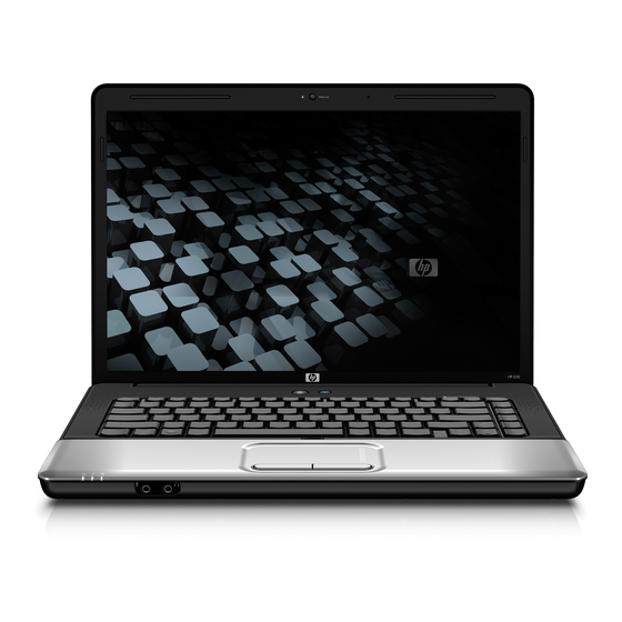
- Page 1 HP G50 Notebook PC and Compaq Presario CQ50 Notebook PC Maintenance and Service Guide...
- Page 2 Corporation. SD Logo is a trademark of its proprietor. The information contained herein is subject to change without notice. The only warranties for HP products and services are set forth in the express warranty statements accompanying such products and services. Nothing herein should be construed as constituting an additional warranty.
- Page 3 Safety warning notice WARNING! To reduce the possibility of heat-related injuries or of overheating the computer, do not place the computer directly on your lap or obstruct the computer air vents. Use the computer only on a hard, flat surface. Do not allow another hard surface, such as an adjoining optional printer, or a soft surface, such as pillows or rugs or clothing, to block airflow.
- Page 4 Safety warning notice...
-
Page 5: Table Of Contents
Table of contents 1 Product description 2 External component identification Top components ... 6 Display components ... 6 Buttons and speakers ... 7 Keys ... 8 TouchPad ... 9 Front components ... 10 Right-side components ... 11 Rear component ... 11 Left-side components ... - Page 6 Unknown user password ... 37 Component replacement procedures ... 38 Serial number ... 38 Computer feet ... 39 Battery ... 40 Optical drive ... 41 Hard drive ... 43 RTC battery ... 46 Memory module ... 47 WLAN module ... 49 Keyboard ...
- Page 7 Computer specifications ... 93 15.4-inch, WXGA display specifications ... 94 Hard drive specifications ... 95 DVD±RW and CD-RW SuperMulti Double-Layer Combo Drive specifications ... 96 Blu-ray BD-ROM with SuperMulti DVD±RW and CD-RW Double-Layer Combo Drive specifications ... 97 System DMA specifications ... 98 System interrupt specifications ...
- Page 8 Universal Serial Bus ... 128 10 Power cord set requirements Requirements for all countries and regions ... 129 Requirements for specific countries and regions ... 130 11 Recycling Battery ... 131 Display ... 131 Index ... 137 viii...
-
Page 9: Product Description
Product description Category Product Name Processors Description HP G50 Notebook PC Compaq Presario CQ50 Notebook PC AMD processors: Turion™ Ultra Dual-Core ZM-82 2.20-GHz processor (35W, 2-MB L2 cache) Turion Ultra Dual-Core ZM-80 2.10-GHz processor (35W, 2-MB L2 cache) Turion Dual-Core RM-70 2.00-GHz processor (35W, 1-MB L2 cache) Athlon™... - Page 10 1024-MB total system memory (1024 × 1, 512 × 2, dual-channel) 512-MB total system memory (512 × 1, only on computer models equipped with FreeDOS and Windows Vista® Basic) HP G50 Notebook PC Compaq Presario CQ50 Notebook PC √ √...
- Page 11 Ethernet Integrated 10/100 network interface card (NIC) Wireless Integrated WLAN options by way of wireless module: 2 wireless antennae built into display assembly Support for no-WLAN option HP G50 Notebook PC Compaq Presario CQ50 Notebook PC √ √ √ √...
- Page 12 Windows Vista Starter Edition 32 Chapter 1 Product description Atheros AR9280 802.11a/b/g/n Atheros AR2425 802.11b/g Broadcom BCM4312 802.11b/g 12-cell, 2.20-Ah, 95-Wh 6-cell, 2.55-Ah, 55-Wh 6-cell, 2.20-Ah, 47-Wh HP G50 Notebook PC Compaq Presario CQ50 Notebook PC √ √ √ √ √...
- Page 13 Category Description FreeDOS Serviceability End-user replaceable parts: AC adapter Battery (system) Hard drive Memory module Optical drive WLAN module HP G50 Notebook PC Compaq Presario CQ50 Notebook PC √ √ √ √ √ √ √ √ √ √ √ √...
-
Page 14: External Component Identification
External component identification Top components Display components Item Component Wireless antennae (2, select models only) Integrated webcam light (select models only) Chapter 2 External component identification Description Send and receive signals from one or more wireless devices. NOTE: The antennae are not visible from the outside of the computer. -
Page 15: Buttons And Speakers
Item Component Integrated webcam (select models only) Internal microphone Buttons and speakers Item Component Speakers (2) Power button Wireless button Description Records audio and video and captures still photographs. Records sound. Description Produce sound. ● When the computer is off, press the button to turn on the computer. -
Page 16: Keys
Keys Item Component Windows logo key Embedded numeric keypad keys Windows applications key Volume keys Function keys Chapter 2 External component identification Function Displays system information when pressed in combination with the key. Executes frequently used system functions when pressed in combination with a function key or the Displays the Windows Start menu. -
Page 17: Touchpad
TouchPad Item Component TouchPad light TouchPad* Left TouchPad button* Right TouchPad button TouchPad vertical scroll zone* TouchPad on/off button *This table describes factory settings. To view and change TouchPad preferences, select Start > Control Panel > Hardware and Sound > Mouse. Function ●... -
Page 18: Front Components
Front components Item Component Power light Battery light Drive light Audio-in (microphone) jack Audio-out (headphone) jack NOTE: This table describes factory settings. For information about changing factory settings, refer to the user guides located in Help and Support. Chapter 2 External component identification Function ●... -
Page 19: Right-Side Components
Right-side components Item Component Optical drive Optical drive light USB ports (2) RJ-11 (modem) jack Security cable slot Rear component Component Vent Function Reads optical discs and, on select models, also writes to optical discs. Blinking: The optical drive is being accessed. Connect an optional USB devices. -
Page 20: Left-Side Components
Left-side components Item Component Power connector AC adapter light External monitor port RJ-45 (network) jack HDMI port USB port Digital Media Slot Digital Media Slot light Chapter 2 External component identification Function Connects an AC adapter. ● On: The computer is connected to external power. ●... -
Page 21: Bottom Components
Bottom components Item Component Battery bay Battery release latch WLAN module compartment Vents (4) Memory module compartment Hard drive bay Function Holds the battery. Releases the battery from the battery bay. Holds the WLAN module. CAUTION: To prevent an unresponsive system, replace the wireless module only with a wireless module authorized for use in the computer by the governmental agency that regulates wireless devices in your country or region. -
Page 22: Illustrated Parts Catalog
Illustrated parts catalog Serial number location When ordering parts or requesting information, provide the computer serial number and model number located on the bottom of the computer. Chapter 3 Illustrated parts catalog... -
Page 23: Computer Major Components
Computer major components Computer major components... - Page 24 Description 15.4-inch, WXGA+BrightView display assemblies (include 2 WLAN antenna transceivers and cables, microphones and cables, and logo) For use only with HP G50 computer models Includes webcam module and cable Does not include webcam module and cable For use only with Compaq CQ50 computer models...
- Page 25 For use only with HP G50 and Compaq CQ50 computer models equipped with a Digital Media Slot and an HDMI port For use only with HP G50 and Compaq CQ50 computer models equipped only with a Digital Media Slot For use only with Compaq CQ50 computer models equipped with an HDMI port...
- Page 26 Item Description ● Intel Core2 Duo P7350 2.00-GHz processor (3-MB L2 cache) ● Intel Core2 Duo T5900 2.20-GHz processor (2-MB L2 cache) ● Intel Core2 Duo T5800 2.00-GHz processor (2-MB L2 cache) ● Intel Pentium Dual-Core T3400 2.16-GHz processor (1-MB L2 cache) ●...
- Page 27 Item Description 160-GB, 5400-rpm 120-GB, 5400-rpm Hard Drive Hardware Kit (includes hard drive bracket, connector, and screws) (21) RTC battery (22) Memory modules For models equipped with AMD processors: PC2-6400, 667-MHz, DDR2 2048-MB 1024-MB 512-MB PC2-5300, 667-MHz, DDR2 2048-MB 1024-MB 512-MB For models equipped with Intel processors: PC2-6400, 667-MHz, DDR2...
- Page 28 Item Description Mauritania, Mauritius, Mexico, Micronesia, Monaco, Mongolia, Montenegro, Morocco, Mozambique, Namibia, Nauru, Nepal, the Nether Antilles, the Netherlands, New Zealand, Nicaragua, Niger, Nigeria, Norway, Oman, Pakistan, Palau, Panama, Papua New Guinea, Paraguay, the People's Republic of China, Peru, the Philippines, Poland, Portugal, the Republic of Moldova, Romania, Russia, Rwanda, Samoa, San Marino, Sao Tome and Principe, Saudi Arabia, Senegal, Serbia and Montenegro, the Seychelles, Sierra Leone, Singapore, Slovakia, Slovenia, the Solomon Islands,...
- Page 29 Item Description Burkina Faso, Burundi, Cameroon, Cape Verde, the Central African Republic, Chad, Chile, Colombia, Comoros, the Congo, Costa Rica, Croatia, Cyprus, the Czech Republic, Denmark, Djibouti, Dominica, the Dominican Republic, East Timor, Ecuador, Egypt, El Salvador, Equitorial Guinea, Eritrea, Estonia, Ethiopia, Fiji, Finland, France, French Guiana, Gabon, Gambia, Georgia, Germany, Ghana, Gibraltar, Greece, Grenada, Guadeloupe, Guatemala, Guinea, Guinea-Bissau, Guyana, Haiti, Honduras, Hong Kong, Hungary, Iceland, India, Ireland, Israel, Italy, the Ivory Coast,...
-
Page 30: Display Assembly Components
Item Description Display bezels: For use only with HP G50 computer models equipped with a webcam module and a microphone For use only with HP G50 computer models equipped only with a microphone For use only with Compaq CQ50 computer models equipped with a webcam module and... -
Page 31: Plastics Kit
Item Description (10) Display enclosures (include logo) For use only with HP G50 computer models For use only with Compaq CQ50 computer models Display Rubber Kit (not illustrated, includes display bezel rubber screw covers) Display Screw Kit (not illustrated) Plastics Kit... -
Page 32: Mass Storage Devices
Mass storage devices Item Description Hard drives (include connector and bracket ) 250-GB, 5400-rpm 200-GB, 5400-rpm 160-GB, 5400-rpm 120-GB, 5400-rpm Hard Drive Hardware Kit (includes connector, bracket, and screws) Optical drives (include bezel and bracket) DVD±RW and CD-RW SuperMulti Double-Layer Combo Drive with LightScribe DVD±RW and CD-RW SuperMulti Double-Layer Combo Drive Blu-ray BD-ROM with SuperMulti DVD±RW and CD-RW Double-Layer Combo Drive Chapter 3 Illustrated parts catalog... -
Page 33: Miscellaneous Parts
Miscellaneous parts Description 65-W PFC AC adapter Power cords: For use in Argentina For use in Australia For use in Denmark For use in Europe For use in India For use in Israel For use in Italy For use in South Africa For use in South Korea For use in Switzerland For use in Taiwan... -
Page 34: Sequential Part Number Listing
Sequential part number listing Spare part Description number 459263-001 Broadcom BCM4312 802.11b/g WLAN module for use in Canada, the Cayman Islands, Guam, Puerto Rico, the U.S. Virgin Islands, and the United States 459263-002 Broadcom BCM4312 802.11b/g WLAN module for use in Afghanistan, Albania, Algeria, Andorra, Angola, Antigua and Barbuda, Argentina, Armenia, Aruba, Australia, Austria, Azerbaijan, the Bahamas, Bahrain, Bangladesh, Barbados, Belarus, Belgium, Belize, Benin, Bermuda, Bhutan, Bolivia, Bosnia and Herzegovina, Botswana, Brazil, the British Virgin Islands, Brunei, Bulgaria, Burkina Faso, Burundi, Cameroon, Cape Verde,... - Page 35 Spare part Description number 480856-005 AMD Athlon X2 Dual-Core QL-60 1.90-GHz processor (35W, 512-KB L2 cache, includes replacement thermal material) 480857-005 AMD Turion Dual-Core RM-70 2.00-GHz processor (35W, 1-MB L2 cache, includes replacement thermal material) 480985-001 Atheros AR9280 802.11a/b/g/n WLAN module for use in Antigua & Barbuda, Argentina, Aruba, the Bahamas, Barbados, Bermuda, Brunei, Canada, the Cayman Islands, Chile, Colombia, Costa Rica, the Dominican Republic, Ecuador, El Salvador, Guam, Guatemala, Haiti, Honduras, Hong Kong, India, Indonesia, Malaysia, Mexico, Panama, Paraguay, Peru, Saudi Arabia, Taiwan, Uruguay, the United States, Venezuela, and Vietnam...
- Page 36 CQ50 computer models (includes 2 WLAN antenna transceivers and cables, microphones and cables, and logo) 485218-001 For use only with HP G50 and Compaq CQ50 computer models equipped with a GM45 chipset, Digital Media Slot, and HDMI port 485219-001 For use only with HP G50 and Compaq CQ50 computer models equipped with a GL40 chipset, Digital Media...
- Page 37 Spare part Description number 486560-001 Microphone (includes receiver and cable) 486561-001 Display panel cable 486562-001 Wireless Antenna Kit (includes left and light wireless antenna transceivers and cables) 486581-001 Webcam module (does not include webcam module cable) 486582-001 Display bezel for use only with Compaq CQ50 computer models equipped with a webcam module and a microphone 486583-001 Webcam module cable...
- Page 38 Display bezel for use only with HP G50 computer models equipped only with a microphone 487607-001 Display bezel for use only with HP G50 computer models equipped with a webcam module and a microphone 488338-001 For use only with HP G50 and Compaq CQ50 computer models equipped with NVIDIA GeForce 9200M graphics, a Digital Media Slot, and an HDMI port 488341–001...
- Page 39 Base enclosure for use only with computer models not equipped with a Digital Media Slot or an HDMI port (includes rubber feet) 494281-001 For use only with HP G50 and Compaq CQ50 computer models equipped with a GM45 chipset and Digital Media Slot 494282-001...
-
Page 40: Removal And Replacement Procedures
Removal and replacement procedures Preliminary replacement requirements Tools required You will need the following tools to complete the removal and replacement procedures: ● Flat-bladed screwdriver ● Magnetic screwdriver ● Phillips P0 and P1 screwdrivers Service considerations The following sections include some of the considerations that you must keep in mind during disassembly and assembly procedures. -
Page 41: Cables And Connectors
Cables and connectors CAUTION: When servicing the computer, be sure that cables are placed in their proper locations during the reassembly process. Improper cable placement can damage the computer. Cables must be handled with extreme care to avoid damage. Apply only the tension required to unseat or seat the cables during removal and insertion. -
Page 42: Grounding Guidelines
Grounding guidelines Electrostatic discharge damage Electronic components are sensitive to electrostatic discharge (ESD). Circuitry design and structure determine the degree of sensitivity. Networks built into many integrated circuits provide some protection, but in many cases, ESD contains enough power to alter device parameters or melt silicon junctions. A discharge of static electricity from a finger or other conductor can destroy static-sensitive devices or microcircuitry. -
Page 43: Packaging And Transporting Guidelines
Packaging and transporting guidelines Follow these grounding guidelines when packaging and transporting equipment: ● To avoid hand contact, transport products in static-safe tubes, bags, or boxes. ● Protect ESD-sensitive parts and assemblies with conductive or approved containers or packaging. ● Keep ESD-sensitive parts in their containers until the parts arrive at static-free workstations. -
Page 44: Equipment Guidelines
Equipment guidelines Grounding equipment must include either a wrist strap or a foot strap at a grounded workstation. ● When seated, wear a wrist strap connected to a grounded system. Wrist straps are flexible straps with a minimum of one megohm ±10% resistance in the ground cords. To provide proper ground, wear a strap snugly against the skin at all times. -
Page 45: Unknown User Password
Unknown user password If the computer you are servicing has an unknown user password, follow these steps to clear the password: NOTE: These steps also clear CMOS. Shut down the computer. If you are unsure whether the computer is off or in Hibernation, turn the computer on, and then shut it down through the operating system. -
Page 46: Component Replacement Procedures
Make special note of each screw and standoff size and location during removal and replacement. Serial number Report the computer serial number to HP when requesting information or ordering spare parts. The serial number is located on the bottom of the computer. Chapter 4 Removal and replacement procedures... -
Page 47: Computer Feet
Computer feet The computer feet are adhesive-backed rubber pads. The feet are included in the Rubber Kit, spare part number 486623-001. There are 6 rubber feet that attach to the base enclosure in the locations illustrated below. Component replacement procedures... -
Page 48: Battery
Battery Description 12-cell, 2.20-Ah, 95-Wh Li-ion battery 6-cell, 2.55-Ah, 55-Wh Li-ion battery 6-cell, 2.20-Ah, 47-Wh Li-ion battery Before disassembling the computer, follow these steps: Shut down the computer. If you are unsure whether the computer is off or in Hibernation, turn the computer on, and then shut it down through the operating system. -
Page 49: Optical Drive
Optical drive NOTE: All optical drive spare part kits include an optical drive bezel and optical drive bracket. Description For models equipped with AMD processors: DVD±RW and CD-RW SuperMulti Double-Layer Combo Drive with LightScribe DVD±RW and CD-RW SuperMulti Double-Layer Combo Drive For models equipped with Intel processors: DVD±RW and CD-RW SuperMulti Double-Layer Combo Drive with LightScribe DVD±RW and CD-RW SuperMulti Double-Layer Combo Drive... - Page 50 If it is necessary to replace the optical drive bracket, position the optical drive with the rear toward you. Remove the two Phillips PM2.0×3.0 screws (1) that secure the optical drive bracket to the optical drive. Remove the optical drive bracket (2). Reverse this procedure to reassemble and install an optical drive.
-
Page 51: Hard Drive
Hard drive NOTE: All hard drive spare part kits include a hard drive bracket and hard drive connector. The hard drive bracket and hard drive connector, as well as the hard drive bracket screws, are also available in the Hard Drive Hardware Kit, spare part number 485037-001. Description For models equipped with AMD processors: 250-GB, 5400-rpm hard drive... - Page 52 Lift the right side of the hard drive cover (2), swing it up and to the left, and remove the cover. The hard drive cover is included in the Plastics Kit, spare part number 486621-001. Remove the three Phillips PM2.5×5.0 screws (1) that secure the hard drive to the computer. Grasp the Mylar tab (2) on the hard drive, and then slide the hard drive (3) to the right to disconnect it from the system board.
- Page 53 Lift the bracket (2) straight up to remove it from the hard drive. Reverse this procedure to reassemble and install the hard drive. Component replacement procedures...
-
Page 54: Rtc Battery
RTC battery NOTE: Removing the RTC battery and leaving it uninstalled for 5 or more minutes causes all passwords and CMOS settings to be cleared. Description RTC battery Before removing the RTC battery, follow these steps: Shut down the computer. If you are unsure whether the computer is off or in Hibernation, turn the computer on, and then shut it down through the operating system. -
Page 55: Memory Module
Memory module Description For models equipped with AMD processors: PC2-6400, 667-MHz, DDR2 2048-MB 1024-MB 512-MB PC2-5300, 667-MHz, DDR2 2048-MB 1024-MB 512-MB For models equipped with Intel processors: PC2-6400, 667-MHz, DDR2 2048-MB 1024-MB 512-MB PC2-5300, 667-MHz, DDR2 2048-MB 1024-MB 512-MB Before removing the memory module, follow these steps: Shut down the computer. - Page 56 Lift the right side of the cover (2), swing it up and to the left, and remove the cover (3). The memory module compartment cover is included in the base enclosure. Spread the retaining tabs (1) on each side of the memory module slot to release the memory module.
-
Page 57: Wlan Module
WLAN module Description Atheros AR9280 802.11a/b/g/n WLAN modules: For use in Canada, the Cayman Islands, Guam, Puerto Rico, the U.S. Virgin Islands, and the United States For use in Afghanistan, Albania, Algeria, Andorra, Angola, Antigua and Barbuda, Argentina, Armenia, Aruba, Australia, Austria, Azerbaijan, the Bahamas, Bahrain, Bangladesh, Barbados, Belarus, Belgium, Belize, Benin, Bermuda, Bhutan, Bolivia, Bosnia and Herzegovina, Botswana, Brazil, the British Virgin Islands, Brunei, Bulgaria, Burkina Faso, Burundi, Cameroon, Cape Verde, the Central African Republic, Chad, Chile, Colombia, Comoros, the Congo, Costa Rica, Croatia,... - Page 58 Description Suriname, Swaziland, Sweden, Switzerland, Taiwan, Tajikistan, Tanzania, Togo, Tonga, Trinidad and Tobago, Tunisia, Turkey, Turkmenistan, Tuvalu, Uganda, Ukraine, the United Arab Emirates, the United Kingdom, Uruguay, Uzbekistan, Vanuatu, Venezuela, Vietnam, Yemen, Zaire, Zambia, and Zimbabwe 802.11a/b/g WLAN module for use in the United States and Canada Atheros AR2425 802.11b/g WLAN modules: For use in Canada, the Cayman Islands, Guam, Puerto Rico, the U.S.
- Page 59 Lift the right side of the cover (2), swing it up and to the left, and then remove the cover (3). The WLAN module compartment cover is included in the Plastics Kit, spare part number 486621-001. Disconnect the WLAN antenna cables (1) from the terminals on the WLAN module. NOTE: The black WLAN antenna cable is connected to the WLAN module “Main”...
-
Page 60: Keyboard
Keyboard For use in: Belgium Canada The Czech Republic Denmark, Finland, and Norway France Germany Greece Israel Italy Latin America The Netherlands Before removing the keyboard, follow these steps: Shut down the computer. If you are unsure whether the computer is off or in Hibernation, turn the computer on, and then shut it down through the operating system. - Page 61 Turn the computer display-side up, with the front toward you. Open the computer as far as possible. Disengage the tabs (1) on the outside edges of the keyboard from the keyboard cover. Lift the rear edge of the keyboard (2), and then slide it back until it rests on the display. Release the zero insertion force (ZIF) connector (1) to which the keyboard cable is attached, and then disconnect the keyboard cable (2) from the system board.
-
Page 62: Keyboard Cover
Keyboard cover Description Keyboard cover (includes an LED board and LED board cable) Before removing the keyboard cover, follow these steps: Shut down the computer. If you are unsure whether the computer is off or in Hibernation, turn the computer on, and then shut it down through the operating system. Disconnect all external devices connected to the computer. - Page 63 Release the ZIF connector (1) to which the power button board cable is attached, and disconnect the power button board cable (2) from the system board. Slide the keyboard cover (1) toward the display assembly until it disengages from the top cover. Remove the keyboard cover (2).
-
Page 64: Power Button Board
Power button board Description Power button board (includes cable) Before removing the power button board, perform these steps: Shut down the computer. If you are unsure whether the computer is off or in Hibernation, turn the computer on, and then shut it down through the operating system. Disconnect all external devices connected to the computer. -
Page 65: Display Assembly
Display assembly Description 15.4-inch, WXGA+BrightView display assembly for use only with HP G50 computer models (includes 2 WLAN antenna transceivers and cables, microphones and cables, and logo) Includes webcam module and cable Does not include webcam module and cable 15.4-inch, WXGA+BrightView display assembly for use only with Compaq CQ50 computer models (includes 2 WLAN antenna... - Page 66 Disconnect the webcam module cable (4) from the system board. CAUTION: The display assembly will be unsupported when the following screws are removed. To prevent damage to the display assembly, support it before removing the screws. Remove the four Phillips PM2.5×10.0 screws (1) that secure the display assembly to the computer. Lift the display assembly (2) straight up and remove it.
- Page 67 For use only with HP G50 computer models equipped with webcam module, spare part number 487607-001 ● For use only with HP G50 computer models not equipped with webcam module, spare part number 487606-001 ● For use only with Compaq CQ50 computer models equipped with webcam module, spare part number 486582-001 ●...
- Page 68 If it is necessary to replace the webcam module, release the webcam module (1) as far from the display enclosure as the webcam module cable allows. Disconnect the webcam module cable (2) from the webcam module. Remove the webcam module. The webcam module is available using spare part number 486581-001.
- Page 69 Disconnect the display panel cable (2) and the backlight cable (3) from the display inverter. Remove the display inverter from the display enclosure. The display inverter is available using spare part number 486556-001. If it is necessary to replace the hinges, remove the two Phillips PM2.5×7.0 screws (1) that secure each hinge to the display enclosure.
- Page 70 Remove the display panel (2) from the display enclosure. The display panel is available using spare part number 485027-001. If it is necessary to replace the display panel brackets, remove the three Phillips PM2.0×3.0 screws (1) that secure the brackets to the display panel. Remove the display panel brackets (2) from the display panel.
- Page 71 Remove the wireless antenna transceivers and cables (4) from the display enclosure. The wireless antenna transceivers and cables are available using spare part number 486562-001. If it is necessary to replace the microphone and cable, release the tab built into the display enclosure shielding (1) that secures the microphone cable.
-
Page 72: Top Cover
Top cover Description Top cover (includes TouchPad and TouchPad cable) Before removing the top cover, follow these steps: Shut down the computer. If you are unsure whether the computer is off or in Hibernation, turn the computer on, and then shut it down through the operating system. Disconnect all external devices connected to the computer. - Page 73 Release the ZIF connector to which the TouchPad cable is attached, and disconnect the TouchPad cable (1) from the system board. Remove the four Phillips PM2.0×6.0 screws (2) that secure the top cover to the base enclosure. Lift the rear edge of the top cover (1) until the top cover disengages from the base enclosure. Remove the top cover (2).
-
Page 74: Touchpad On/Off Button Board
TouchPad on/off button board Description TouchPad on/off button board (includes cables) Before removing the TouchPad on/off button board, follow these steps: Shut down the computer. If you are unsure whether the computer is off or in Hibernation, turn the computer on, and then shut it down through the operating system. Disconnect all external devices connected to the computer. - Page 75 Release the ZIF connector on the TouchPad board to which the TouchPad on/off board cable is attached, and disconnect the TouchPad on/off board cable (2) from the TouchPad board. Remove the two Phillips PM2.0×3.0 screws (1) that secure the TouchPad on/off button board to the top cover.
-
Page 76: Touchpad Button Board
TouchPad button board Description TouchPad button board Before removing the TouchPad button board, follow these steps: Shut down the computer. If you are unsure whether the computer is off or in Hibernation, turn the computer on, and then shut it down through the operating system. Disconnect all external devices connected to the computer. - Page 77 Turn the TouchPad button board bracket upside down with the front toward you. Remove the two Phillips PM2.0×3.0 screws (1) that secure the TouchPad button board to the TouchPad button board bracket. Remove the TouchPad button board (2) from the TouchPad button board bracket. Reverse this procedure to install the TouchPad button board.
-
Page 78: Audio Board
Audio board Description Audio board (includes cable) Before removing the audio board, follow these steps: Shut down the computer. If you are unsure whether the computer is off or in Hibernation, turn the computer on, and then shut it down through the operating system. Disconnect all external devices connected to the computer. -
Page 79: Bluetooth Module
Reverse this procedure to install the audio board. Bluetooth module Description Bluetooth module (does not include Bluetooth module cable) Bluetooth module cable Before removing the Bluetooth module, follow these steps: Shut down the computer. If you are unsure whether the computer is off or in Hibernation, turn the computer on, and then shut it down through the operating system. -
Page 80: Speakers
Remove the Bluetooth module (3). Reverse this procedure to install the Bluetooth module. Speakers Description Speakers Before removing the speakers, follow these steps: Shut down the computer. If you are unsure whether the computer is off or in Hibernation, turn the computer on, and then shut it down through the operating system. -
Page 81: Usb Board
Disconnect the speaker cable (2) from the system board. Remove the Phillips PM2.0×3.0 screw (1) that secures the left speaker to the base enclosure. Remove the Phillips PM2.0×6.0 screw (2) that secures the right speaker to the base enclosure. Remove the left and right speakers and the speaker cables (3) from the base enclosure. Reverse this procedure to install the speakers. -
Page 82: System Board
Before removing the USB board, follow these steps: Shut down the computer. If you are unsure whether the computer is off or in Hibernation, turn the computer on, and then shut it down through the operating system. Disconnect all external devices connected to the computer. Disconnect the power from the computer by first unplugging the power cord from the AC outlet and then unplugging the AC adapter from the computer. - Page 83 For use only with HP G50 and Compaq CQ50 computer models equipped with a Digital Media Slot and an HDMI port For use only with HP G50 and Compaq CQ50 computer models equipped only with a Digital Media Slot For use only with Compaq CQ50 computer models equipped with an HDMI port...
- Page 84 When replacing the system board, be sure that the following components are removed from the defective system board and installed on the replacement system board: ● Memory modules (see ● RTC battery (see ● WLAN module (see ● Fan/heat sink assembly (see ●...
-
Page 85: Rj-11 Connector Cable
Remove the two Phillips PM2.5×10.0 screws that secure the system board to the base enclosure. Use the optical drive connector (1) to lift the right side of the system board (2) until it rests at an angle. Remove the system board (3) by pulling it away from the base enclosure at an angle. Reverse this procedure to install the system board. - Page 86 Remove the battery (see Remove the following components: Hard drive (see Optical drive (see Keyboard (see Keyboard cover (see Display assembly (see Top cover (see Speakers (see System board (see Remove the RJ-11 connector cable: Remove the RJ-11 connector from the clip (1) built into the base enclosure. Remove the RJ-11 connector cable (2) from the clips and routing channels built into the base enclosure.
-
Page 87: Fan/Heat Sink Assembly
Fan/heat sink assembly Description Fan/heat sink assembly (includes replacement thermal material) Before removing the fan/heat sink assembly, follow these steps: Shut down the computer. If you are unsure whether the computer is off or in Hibernation, turn the computer on, and then shut it down through the operating system. Disconnect all external devices connected to the computer. - Page 88 Remove the fan/heat sink assembly: Disconnect the fan cable from the system board. Turn the system board upside down, with the RJ-11 and RJ-45 jacks toward you. Loosen the four Phillips PM2.0×10.0 captive screws (1) that secure the fan/heat sink assembly to the system board.
- Page 89 Reverse this procedure to install the fan/heat sink assembly. Component replacement procedures...
-
Page 90: Processor
Processor NOTE: All processor spare part kits include replacement thermal material. Description AMD Turion Ultra Dual-Core ZM-82 2.20-GHz processor (35W, 2-MB L2 cache) AMD Turion Ultra Dual-Core ZM-80 2.10-GHz processor (35W, 2-MB L2 cache) AMD Turion Dual-Core RM-70 2.00-GHz processor (35W, 1-MB L2 cache) AMD Athlon Dual-Core QL-60 1.90-GHz processor (35W, 1-MB L2 cache) AMD Sempron Single-Core SI-40 2.00-GHz processor (25W, 512-KB L2 cache) Processor bracket (AMD) -
Page 91: Power Connector Cable
Display assembly (see Top cover (see Speakers (see System board (see Fan/heat sink assembly (see Remove the processor: Use a flat-bladed screwdriver to turn the processor locking screw (1) one-half turn counterclockwise until you hear a click. Lift the processor (2) straight up and remove it. NOTE: When you install the processor, the gold triangle (3) on the processor must be aligned with the triangle (4) embossed on the processor socket. - Page 92 Remove the battery (see Remove the following components: Optical drive (see Hard drive (see Keyboard (see Keyboard cover (see Display assembly (see Top cover (see System board (see Remove the power connector cable: Position the system board with the front toward you. Disconnect the power connector cable from the system board.
-
Page 93: Setup Utility
Setup Utility WARNING! Only authorized technicians trained by HP must repair this equipment. All troubleshooting and repair procedures are detailed to allow repair at only the subassembly or module level. Because of the complexity of the individual boards and subassemblies, do not attempt to make repairs at the component level or modify any printed wiring board. -
Page 94: Navigating And Selecting In The Setup Utility
Use the arrow keys to select a language, and then press enter. When a confirmation prompt with your language selected is displayed, press enter. To save your change and exit the Setup Utility, use the arrow keys to select Exit > Exit Saving Changes, and then press enter. -
Page 95: Restoring Default Settings In The Setup Utility
Restoring default settings in the Setup Utility The following procedure explains how to restore the Setup Utility default settings. If the Setup Utility is not already running, begin at step 1. If the Setup Utility is already running, begin at step 2. Open the Setup Utility by turning on or restarting the computer. -
Page 96: Exiting The Setup Utility
Exiting the Setup Utility You can exit the Setup Utility with or without saving changes. ● To exit the Setup Utility and save your changes from the current session: If the Setup Utility menus are not visible, press arrow keys to select Exit > Exit Saving Changes, and then press enter. ●... -
Page 97: Main Menu
Main menu Select System information To do this ● View and change the system time and date. ● View identification information about the computer. ● View specification information about the processor, memory size, system BIOS, and keyboard controller version (select models only). Main menu... -
Page 98: Security Menu
Security menu Select Administrator password Power-On Password Chapter 5 Setup Utility To do this Enter, change, or delete an administrator password. Enter, change, or delete a power-on password. -
Page 99: System Configuration Menu
System Configuration menu Select Language Support Button Sound (select models only) Virtualization Technology Processor C4 State (select models only) LAN Power Saving (select models only) Card Reader/1394 Power Saving (select models only) Fan Always On Boot Options To do this Change the Setup Utility language. -
Page 100: Diagnostics Menu
Diagnostics menu Select Hard Disk Self Test Secondary Hard Disk Self Test (select models only) Memory Test Chapter 5 Setup Utility To do this Run a comprehensive self-test on the hard drive. NOTE: On models with two hard drives, this menu option is called the Primary Hard Disk Self Test. -
Page 101: Specifications
Specifications Computer specifications Dimensions Length Width Height (front to rear) Weight Equipped with 6-cell battery and optical drive Input power Operating voltage Operating current Temperature Operating (not writing to optical disc) Operating (writing to optical disc) Nonoperating Relative humidity Operating Nonoperating Maximum altitude (unpressurized) Operating... -
Page 102: 15.4-Inch, Wxga Display Specifications
Nonoperating NOTE: Applicable product safety standards specify thermal limits for plastic surfaces. The computer operates well within this range of temperatures. 15.4-inch, WXGA display specifications Dimensions Height Width Diagonal Number of colors Contrast ratio Brightness Pixel resolution Pitch Format Configuration Backlight Character display Total power consumption... -
Page 103: Hard Drive Specifications
Hard drive specifications Dimensions Height Width Weight Interface type Transfer rate Security Seek times (typical read, including setting) Single track Average Maximum Logical blocks Disc rotational speed Operating temperature *1 GB = 1 billion bytes when referring to hard drive storage capacity. Actual accessible capacity is less. Actual drive specifications may differ slightly. -
Page 104: Dvd±Rw And Cd-Rw Supermulti Double-Layer Combo Drive Specifications
DVD±RW and CD-RW SuperMulti Double-Layer Combo Drive specifications Applicable disc Access time Random Cache buffer Data transfer rate 24X CD-ROM 8X DVD 24X CD-R 16X CD-RW 8X DVD+R 4X DVD+RW 8X DVD-R 4X DVD-RW 2.4X DVD+R(9) 5X DVD-RAM Transfer mode Chapter 6 Specifications Read: CD-DA, CD+(E)G, CD-MIDI, CD-TEXT,... -
Page 105: Blu-Ray Bd-Rom With Supermulti Dvd±Rw And Cd-Rw Double-Layer Combo Drive Specifications
Blu-ray BD-ROM with SuperMulti DVD±RW and CD-RW Double-Layer Combo Drive specifications Applicable disc Access time Random Cache buffer Data transfer rate 24X CD-ROM 8X DVD 24X CD-R 16X CD-RW 8X DVD+R 4X DVD+RW 8X DVD-R 4X DVD-RW 2.4X DVD+R(9) 5X DVD-RAM 1X BD-ROM 1X BD-R read 1X BD-RE read... -
Page 106: System Dma Specifications
System DMA specifications Hardware DMA DMA0 DMA1* DMA2* DMA3 DMA4 DMA5* DMA6 DMA7 *PC Card controller can use DMA 1, 2, or 5. Chapter 6 Specifications System function Not applicable Not applicable Not applicable Not applicable Direct memory access controller Available for PC Card Not assigned Not assigned... -
Page 107: System Interrupt Specifications
System interrupt specifications Hardware IRQ IRQ0 IRQ1 IRQ2 IRQ4 IRQ6 IRQ7* IRQ8 IRQ9* IRQ12 IRQ13 IRQ14 IRQ15 *Default configuration; audio possible configurations are IRQ5, IRQ7, IRQ9, IRQ10, or none. NOTE: PC Cards may assert IRQ3, IRQ4, IRQ5, IRQ7, IRQ9, IRQ10, IRQ11, or IRQ15. Either the infrared or the serial port may assert IRQ3 or IRQ4. -
Page 108: System I/O Address Specifications
System I/O address specifications I/O address (hex) 000 - 00F 010 - 01F 020 - 021 022 - 024 025 - 03F 02E - 02F 040 - 05F 044 - 05F 062 - 063 065 - 06F 070 - 071 072 - 07F 080 - 08F 090 - 091... - Page 109 I/O address (hex) 220 - 22F 230 - 26D 26E - 26 278 - 27F 280 - 2AB 2A0 - 2A7 2A8 - 2E7 2E8 - 2EF 2F0 - 2F7 2F8 - 2FF 300 - 31F 320 - 36F 370 - 377 378 - 37F 380 - 387 388 - 38B...
-
Page 110: System Memory Map Specifications
System memory map specifications Size 640 KB 128 KB 48 KB 160 KB 64 KB 15 MB 58 MB 58 MB 2 MB 4 GB 64 KB 102 Chapter 6 Specifications Memory address 00000000-0009FFFF 000A0000-000BFFFF 000C0000-000CBFFF 000C8000-000E7FFF 000E8000-000FFFFF 00100000-00FFFFFF 04800000-07FFFFFF 04800000-07FFFFFF 08000000-080FFFFF 08200000-FFFEFFFF... -
Page 111: Screw Listing
Screw listing This section provides specification and reference information for the screws used in the computer. The screws listed in this section are available in the Screw Kit, spare part number 486622-001, or the Display Screw Kit, spare part number 486557-001. -
Page 112: Phillips Pm2.5×10.0 Screw
Phillips PM2.5×10.0 screw Color Black Where used: (1) One screw that secures the optical drive to the computer (2) Two screws that secure the keyboard cover to the computer 104 Chapter 7 Screw listing Quantity Length 10.0 mm Thread Head diameter 2.5 mm 5.0 mm... - Page 113 Where used: 4 screws that secure the display assembly to the computer Where used: 2 screws that secure the system board to the base enclosure Phillips PM2.5×10.0 screw 105...
-
Page 114: Phillips Pm2.5×10.0 Captive Screw
Phillips PM2.5×10.0 captive screw Color Black Where used: 4 captive screws that secure the top cover to the computer (screws are secured by C- clips) 106 Chapter 7 Screw listing Quantity Length 10.0 mm Thread Head diameter 2.5 mm 5.0 mm... -
Page 115: Phillips Pm2.0×3.0 Screw
Phillips PM2.0×3.0 screw Color Black Where used: 2 screws that secure the optical drive bracket to the optical drive Where used: 2 screws that secure the keyboard cover to the computer Quantity Length 3.0 mm Thread Head diameter 2.0 mm 4.5 mm Phillips PM2.0×3.0 screw 107... - Page 116 Where used: 2 screws that secure the power button board to the keyboard cover Where used: 6 screws that secure the display panel brackets to the display panel Where used: 2 screws that secure the top cover to the base enclosure 108 Chapter 7 Screw listing...
- Page 117 Where used: (1) Two screws that secure the TouchPad on/off button board to the top cover (2) Four screws that secure the TouchPad button board bracket to the top cover Where used: 2 screws that secure the TouchPad button board to the TouchPad button board bracket Where used: One screw that secures the left speaker to the base enclosure Phillips PM2.0×3.0 screw 109...
-
Page 118: Phillips Pm2.5×6.0 Captive Screw
Phillips PM2.5×6.0 captive screw Color Black Where used: (1) Two captive screws that secure the hard drive cover to the computer (screws are secured by C-clips) (2) Two captive screws that secure the memory module compartment cover to the computer (screws are secured by C-clips) (3) One captive screw that secures the WLAN module compartment cover to the computer (screw is secured by a C-clip) -
Page 119: Phillips Pm2.5×5.0 Screw
Phillips PM2.5×5.0 screw Color Black Where used: (1) Three screws that secure the hard drive to the computer (2) Two screws that secure the WLAN module to the computer (3) Three screws that secure the keyboard to the computer Quantity Length 5.0 mm Thread... - Page 120 Where used: 2 screws that secure the display panel to the display enclosure 112 Chapter 7 Screw listing...
-
Page 121: Phillips Pm3.0×3.0 Screw
Phillips PM3.0×3.0 screw Color Silver Where used: 4 screws that secure the hard drive bracket to the hard drive Quantity Length 3.0 mm Thread Head diameter 3.0 mm 5.0 mm Phillips PM3.0×3.0 screw 113... -
Page 122: Phillips Pm2.5×8.0 Screw
Phillips PM2.5×8.0 screw Color Black Where used: 2 screws that secure the display bezel to the display assembly 114 Chapter 7 Screw listing Quantity Length 8.0 mm Thread Head diameter 2.5 mm 5.0 mm... -
Page 123: Phillips Pm2.5×7.0 Screw
Phillips PM2.5×7.0 screw Color Black Where used: 4 screws that secure the display hinges to the display enclosure Quantity Length 7.0 mm Thread Head diameter 2.5 mm 5.0 mm Phillips PM2.5×7.0 screw 115... -
Page 124: Phillips Pm2.0×6.0 Screw
Phillips PM2.0×6.0 screw Color Black Where used: 2 screws that secure the top cover to the base enclosure Where used: 4 screws that secure the top cover to the base enclosure 116 Chapter 7 Screw listing Quantity Length 6.0 mm Thread Head diameter 2.0 mm... - Page 125 Where used: (1) Two screws that secure the audio board to the base enclosure (2) Two screws that secure the Bluetooth module to the base enclosure Where used: One screw that secures the right speaker to the base enclosure Phillips PM2.0×6.0 screw 117...
-
Page 126: Phillips Pm2.0×11.0 Captive Screw
Phillips PM2.0×11.0 captive screw Color Silver Where used: 4 captives screws that secure the fan/heat sink to the system board (screws are secured by C-clips) 118 Chapter 7 Screw listing Quantity Length 11.0 mm Thread Head diameter 2.0 mm 5.0 mm... -
Page 127: Backup And Recovery
Recovery discs have been included for computers that do not have a partition. Use these discs to recover your operating system and software. To check for the presence of a recovery partition, select Start > Computer. If the partition is present, an HP Recovery drive is listed in the Hard Disk Drives section of the window. -
Page 128: Backing Up Your Information
Note the following guidelines before creating recovery discs: ● You will need high quality CD-R, DVD-R, double-layer DVD-R, DVD+R, double-layer DVD+R, or BD-R (writable Blu-ray) discs. All these discs are purchased separately. NOTE: Read-write discs, such as CD-RW, DVD±RW, double-layer DVD±RW, and BD-RE (rewritable Blu-ray) discs, are not compatible with the Recovery Manager software. -
Page 129: Using System Restore Points
To copy the screen and paste it into a word-processing document, follow these steps: Display the screen. Copy the screen: To copy only the active window, press To copy the entire screen, press Open a word-processing document, and then select Edit > Paste. Using system restore points When you back up your system, you are creating a system restore point. - Page 130 Click the System Restore button, and then click Next. The System Restore window opens. Follow the on-screen instructions. 122 Chapter 8 Backup and recovery...
-
Page 131: Performing A Recovery
Performing a recovery NOTE: You can recover only files that you have previously backed up. HP recommends that you use Recovery Manager to create an entire drive backup as soon as you set up your computer. Recovery Manager software allows you to repair or restore the system if you experience system failure or instability. -
Page 132: Connector Pin Assignments
Connector pin assignments Audio-out (headphone) Audio-in (microphone) 124 Chapter 9 Connector pin assignments Signal Audio out, left channel Audio out, right channel Ground Signal Audio signal in Audio signal in Ground... -
Page 133: External Monitor
External monitor Signal Red analog Green analog Blue analog Not connected Ground Ground analog Ground analog Ground analog +5 VDC Ground Monitor detect DDC 2B data Horizontal sync Vertical sync DDC 2B clock External monitor 125... -
Page 134: Modem)
RJ-11 (modem) 126 Chapter 9 Connector pin assignments Signal Unused Ring Unused Unused Unused... -
Page 135: Network)
RJ-45 (network) Signal Transmit + Transmit - Receive + Unused Unused Receive - Unused Unused RJ-45 (network) 127... -
Page 136: Universal Serial Bus
Universal Serial Bus 128 Chapter 9 Connector pin assignments Signal +5 VDC Data - Data + Ground... -
Page 137: 10 Power Cord Set Requirements
10 Power cord set requirements The wide range input feature of the computer permits it to operate from any line voltage from 100 to 120 volts AC or from 220 to 240 volts AC. The 3-conductor power cord set included with the computer meets the requirements for use in the country or region where the equipment is purchased. -
Page 138: Requirements For Specific Countries And Regions
Requirements for specific countries and regions Country/region Australia Austria Belgium Canada Denmark Finland France Germany Italy Japan The Netherlands Norway The People's Republic of China South Korea Sweden Switzerland Taiwan The United Kingdom The United States The flexible cord must be Type HO5VV-F, 3-conductor, 1.0-mm² conductor size. Power cord set fittings (appliance coupler and wall plug) must bear the certification mark of the agency responsible for evaluation in the country or region where it will be used. -
Page 139: 11 Recycling
Careful handling must be exercised when removing these components. NOTE: Materials Disposal. This HP product contains mercury in the backlight in the display assembly that might require special handling at end-of-life. Disposal of mercury may be regulated because of environmental considerations. For disposal or recycling information, contact your local authorities, or see the Electronic Industries Alliance (EIA) Web site at http://www.eiae.org. - Page 140 Perform the following steps to disassemble the display assembly: Remove all screw covers (1) and screws (2) that secure the display bezel to the display assembly. Lift up and out on the left and right inside edges (1) and the top and bottom inside edges (2) of the display bezel until the bezel disengages from the display assembly.
- Page 141 Disconnect all display panel cables (1) from the display inverter and remove the inverter (2). Remove all screws (1) that secure the display panel assembly to the display enclosure. Remove the display panel assembly (2) from the display enclosure. Turn the display panel assembly upside down. Remove all screws that secure the display panel frame to the display panel.
- Page 142 Remove the display panel frame (2) from the display panel. Remove the screws (1) that secure the backlight cover to the display panel. Lift the top edge of the backlight cover (2) and swing it outward. Remove the backlight cover. Turn the display panel right-side up.
- Page 143 Remove the backlight cables (1) from the clip (2) in the display panel. Turn the display panel upside down. Remove the backlight frame from the display panel. WARNING! The backlight contains mercury. Exercise caution when removing and handling the backlight to avoid damaging this component and causing exposure to the mercury. Remove the backlight from the backlight frame.
- Page 144 Disconnect the display cable (1) from the LCD panel. Remove the screws (2) that secure the LCD panel to the display rear panel. Release the LCD panel (3) from the display rear panel. Release the tape (4) that secures the LCD panel to the display rear panel. Remove the LCD panel.
-
Page 145: Index
Index Symbols/Numerics 1394 Power Saving 91 AC adapter light 12 AC adapter, spare part number 25, 26 administrator password 90 antenna disconnecting 51 locations 6 removal 62 spare part number 22, 29, audio board removal 70 spare part number 18, 29, audio, product description 3 audio-in jack location 10... - Page 146 removal 60 spare part number 22, 28, display panel illustrated 22 product description 2 removal 61 spare part number 22, 27, display panel brackets illustrated 22 removal 62 spare part number 22, 28, display panel cable, spare part number 22, 29 Display Rubber Kit, spare part number 23, 29, 59 Display Screw Kit, spare part...
- Page 147 microphone illustrated 22 locations 7 product description 3 removal 63 spare part number 22, 29, microphone jack location 10 pin assignments 124 model name 1 modem jack location 11 pin assignments 126 modem module, product description 3 monitor port location 12 pin assignments 125 navigating in the Setup Utility 86 network jack...
- Page 148 RJ-11 jack location 11 pin assignments 126 RJ-45 jack location 12 pin assignments 127 RTC battery removal 46 spare part number 19, 29, Rubber Kit, spare part number 18, 29 Screw Kit contents 103 spare part number 25, 29 screw listing 103 secondary hard drive self test 92 security cable slot 11 Security menu 90...