HP COMPAQ NC2400 Maintenance And Service Manual
Notebook pc
Hide thumbs
Also See for COMPAQ NC2400:
- Maintenance and service manual (230 pages) ,
- Getting started (68 pages) ,
- Quickspecs (33 pages)
Table of Contents
Advertisement
Maintenance and Service
Guide
HP Compaq nc2400 Notebook PC
Document Part Number: 407949-001
May 2006
This guide is a troubleshooting reference used for maintaining
and servicing the computer. It provides comprehensive
information on identifying computer features, components, and
spare parts; troubleshooting computer problems; and performing
computer disassembly procedures.
Advertisement
Table of Contents
Troubleshooting

Related Manuals for HP COMPAQ NC2400


Summary of Contents for HP COMPAQ NC2400
- Page 1 Maintenance and Service Guide HP Compaq nc2400 Notebook PC Document Part Number: 407949-001 May 2006 This guide is a troubleshooting reference used for maintaining and servicing the computer. It provides comprehensive information on identifying computer features, components, and spare parts; troubleshooting computer problems; and performing...
- Page 2 Hewlett-Packard Company under license. The information contained herein is subject to change without notice. The only warranties for HP products and services are set forth in the express warranty statements accompanying such products and services. Nothing herein should be construed as constituting an additional warranty. HP shall not be liable for technical or editorial errors or omissions contained herein.
-
Page 3: Table Of Contents
1 Product Description 1.1 Features ........1–2 1.2 Resetting the Computer. - Page 4 Contents 3 Illustrated Parts Catalog 3.1 Serial Number Location ..... . 3–1 3.2 Computer Major Components....3–2 3.3 Display Assembly Components .
- Page 5 Contents 5 Removal and Replacement Procedures 5.1 Serial Number ......5–2 5.2 Disassembly Sequence Chart .
-
Page 6: Specifications
Contents 6 Specifications Screw Listing B Backup and Recovery C Display Component Recycling D Connector Pin Assignments E Power Cord Set Requirements Index Maintenance and Service Guide... -
Page 7: Product Description
Product Description The HP Compaq nc2400 Notebook PC offers advanced modularity, Intel® Pentium® M and Celeron® M processors, and extensive multimedia support. HP Compaq nc2400 Notebook PC Maintenance and Service Guide 1–1... -
Page 8: Features
Product Description 1.1 Features ■ The following processors, varying by computer model: ❏ Intel Pentium M 1200 (1.20-GHz) ❏ Intel Pentium M 1100 (1.06-GHz) ❏ Intel Celeron M 423 (1.06-GHz) ■ 12.1-inch, WXGA+WVA, TFT (1280 × 800) with over 16.8 million colors ■... - Page 9 ■ Integrated wireless support for Mini Card IEEE 802.11a/b/g or 802.11b/g Wireless LAN (WLAN) device ■ Support for one Type I or Type II PC Card slot, with support for both 32-bit (CardBus) and 16-bit PC Cards, varying by computer model ■...
-
Page 10: Resetting The Computer
Product Description 1.2 Resetting the Computer If the computer you are servicing has an unknown password, follow the steps below to reset the password. These steps also clear CMOS. ✎ The following steps will not clear an unknown password if the stringent security option has been enabled in the BIOS. -
Page 11: Power Management
1.3 Power Management The computer comes with power management features that extend battery operating time and conserve power. The computer supports the following power management features: ■ Standby ■ Hibernation ■ Setting customization by the user ■ Hotkeys for setting the level of performance ■... -
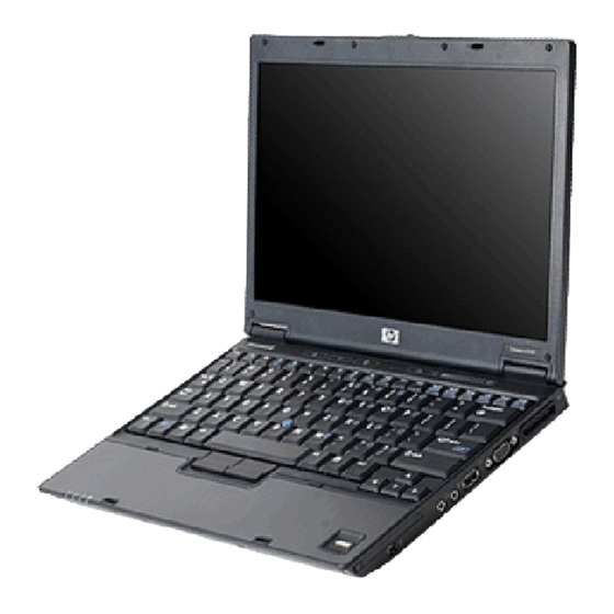
Page 12: External Components
Product Description 1.4 External Components The external components on the front of the computer are shown below and described in Table 1-1. Front Components Item Component Wireless light Power light 1–6 Table 1-1 Front Components Function On: An integrated wireless device, such as a wireless local area network (LAN) device and/or a Bluetooth®... - Page 13 ■ Blinking: The hard drive or optical drive is being accessed. ■ Amber: HP Mobile Data Protection with accelerometer software has temporarily parked the internal hard drive. Opens the computer.
-
Page 14: Right-Side Components
Product Description The external components on the right side of the computer are shown below and described in Table 1-2. Right-Side Components Item Component PC Card slot 1394 port Audio-out (headphone) jack Audio-in (microphone) jack USB port External monitor port Docking connector 1–8 Table 1-2... -
Page 15: Left-Side Components
The external components on the left side of the computer are shown below and described in Table 1-3. Left-Side Components Item Component Smart Adapter power connector RJ-11 (modem) jack USB port Optical drive Maintenance and Service Guide Table 1-3 Left-Side Components Function Connects an AC adapter or an optional power adapter. - Page 16 Product Description The external components on the rear panel of the computer are shown below and described in Table 1-4. Rear Panel Components 1–10 Maintenance and Service Guide...
-
Page 17: Rear Panel Components
Item Component RJ-45 (network) jack Battery bay Security cable slot Maintenance and Service Guide Table 1-4 Rear Panel Components Function Connects an optional network cable. Holds a battery. Attaches an optional security cable to the computer. Ä Security solutions are designed to act as deterrents. - Page 18 Product Description The standard keyboard components of the computer are shown below and described in Table 1-5. Standard Keyboard Components 1–12 Maintenance and Service Guide...
- Page 19 Item Component f1 to f12 keys (12) caps lock key fn key Windows logo key Windows applications Arrow keys Keypad keys (15) num lock key Maintenance and Service Guide Table 1-5 Rear Panel Components Function Perform system and application tasks. When combined with the fn key, several keys and buttons perform additional tasks as hotkeys.
-
Page 20: Top Components
Product Description The computer top components are shown below and described in Table 1-6. Top Components Item Component Power light 1–14 Table 1-6 Top Components Function ■ On: The computer is on. ■ Blinking: The computer is in standby. ■ Blinking rapidly: An AC adapter with a higher power rating should be connected. - Page 21 Top Components (Continued) Item Component Power button Info Center button Wireless button Presentation button Caps lock light Num lock light Volume mute button Volume down button Volume up button Maintenance and Service Guide Table 1-6 Function When the computer is ■...
- Page 22 Product Description The computer top components are shown below and described in Table 1-7. Top Components 1–16 Maintenance and Service Guide...
- Page 23 Item Component Pointing stick buttons Fingerprint reader Pointing stick Maintenance and Service Guide Table 1-7 Top Components Function Function like the left, middle, and right buttons on an external mouse. Allows a fingerprint logon to Windows instead of using a password. Moves the pointer and selects or activates items on the screen.
-
Page 24: Bottom Components
Product Description The external components on the bottom of the computer are shown below and described in Table 1-8. Bottom Components Item Component Battery bay Battery release latches (2) Exhaust vents 1–18 Table 1-8 Bottom Components Function Holds the battery. Release the battery from the battery bay. - Page 25 Bottom Components (Continued) Item Component Hard drive bay Memory module compartment Speaker Bluetooth module compartment Mini Card compartment Maintenance and Service Guide Table 1-8 Function Holds the primary hard drive. Contains one memory slot that supports replaceable memory modules. Produces sound. Holds an optional Bluetooth device.
-
Page 26: Design Overview
Product Description 1.5 Design Overview This section presents a design overview of key parts and features of the computer. Refer to to identify replacement parts, and Replacement Procedures,” The system board provides the following device connections: ■ Audio ■ Display ■... -
Page 27: Troubleshooting
Å WARNING: Only authorized technicians trained by HP should repair this equipment. All troubleshooting and repair procedures are detailed to allow only subassembly-/module-level repair. Because of the complexity of the individual boards and subassemblies, do not attempt to make repairs at the component level or modifications to any printed wiring board. -
Page 28: Selecting From The File Menu
Troubleshooting 2. Select the File, Security, Diagnostics, or System Configuration menu. 3. To close Computer Setup and restart the computer: ❏ Select File > Save changes and exit, and then press – or – ❏ Select File > Ignore changes and exit, and then press –... -
Page 29: Selecting From The Security Menu
Selecting from the Security Menu Select Setup Password Power-On Password Password Options (Password options can be selected only when a power-on password has been set.) DriveLock Passwords Smart Card Security TPM Embedded Security System IDs Disk Sanitizer *Not applicable to SuperDisk LS-120 drives. Maintenance and Service Guide Table 2-2 Security Menu... -
Page 30: Selecting From The Diagnostics Menu
Troubleshooting Selecting from the Diagnostics Menu Select HDD Self-Test Options Memory Check 2–4 Table 2-3 Diagnostics Menu To Do This Run a quick comprehensive self test on hard drives in the system that support the test features. Run a quick comprehensive test on system memory on the following categories: ■... -
Page 31: Selecting From The System Configuration Menu
Selecting from the System Configuration Menu Select Language Boot Options Device Configurations Built-In Device Options Port Options Maintenance and Service Guide Table 2-4 System Configuration Menu To Do This Change the Computer Setup language. Enable/disable MultiBoot, which sets a startup sequence that can include most bootable devices and media in the system. -
Page 32: Troubleshooting Flowcharts
Troubleshooting 2.2 Troubleshooting Flowcharts Troubleshooting Flowcharts Overview Flowchart Description “Flowchart 2.1—Initial Troubleshooting” “Flowchart 2.2—No Power, Part 1” “Flowchart 2.3—No Power, Part 2” “Flowchart 2.4—No Power, Part 3” “Flowchart 2.5—No Power, Part 4” “Flowchart 2.6—No Video, Part 1” “Flowchart 2.7—No Video, Part 2” “Flowchart 2.8—Nonfunctioning Docking Device (if applicable)”... -
Page 33: Flowchart 2.1—Initial Troubleshooting
Flowchart 2.1—Initial Troubleshooting Begin troubleshooting. Is there power? Beeps, LEDs, or error messages? Is there video? (no boot) Is the OS loading? Is there sound? Maintenance and Service Guide Go to “Flowchart 2.2—No Power, Part 1.” Check LED board, speaker connections. -
Page 34: Flowchart 2.2—No Power, Part
Troubleshooting Flowchart 2.2—No Power, Part 1 No power (power LED is off). Remove from docking device (if applicable). Power up on battery power? Power up on AC power? Power up in docking device? 1. Reset the power cables in the docking device and at the AC outlet. -
Page 35: Flowchart 2.3—No Power, Part
Flowchart 2.3—No Power, Part 2 Continued from “Flowchart 2.2—No Power, Part 1.” Visually check for debris in battery socket and clean if necessary. Power on? Check battery by recharging it, moving it to another computer, or replacing it. Power on? Done Maintenance and Service Guide Done... -
Page 36: Flowchart 2.4—No Power, Part
Troubleshooting Flowchart 2.4—No Power, Part 3 Continued from “Flowchart 2.3—No Power, Part 2.” Plug directly into AC outlet. Power LED Reseat AC adapter in computer and at power source. Power on? Power outlet active? Replace power cord. Power on? 2–10 Done Done Internal or... -
Page 37: Flowchart 2.5—No Power, Part
Flowchart 2.5—No Power, Part 4 Continued from “Flowchart 2.4—No Power, Part 3.” Open computer. Loose or damaged parts? Close computer and retest. Power on? Done Maintenance and Service Guide Reseat loose components and boards and replace damaged items. Replace the following items (if applicable). Check computer operation after each replacement: 1. -
Page 38: Flowchart 2.6—No Video, Part
Troubleshooting Flowchart 2.6—No Video, Part 1 No video. Docking Device Stand-alone or docking device? Stand-alone Internal or external display*? Internal External Adjust brightness. Video OK? Replace the following one at a time. Test after each replacement. Check for bent pins on cable. Video OK? Done 2–12... -
Page 39: Flowchart 2.7—No Video, Part
Flowchart 2.7—No Video, Part 2 Continued from “Flowchart 2.6—No Video, Part 1.” Remove computer from docking device, if connected. Adjust display brightness. Video OK? Check that computer is properly seated in docking device, for bent pins on cable, and for monitor connection. - Page 40 Troubleshooting Flowchart 2.8—Nonfunctioning Docking Device (if applicable) Nonfunctioning docking device. Reset power cord in docking device and power outlet. Check voltage setting on docking device. Reset monitor cable connector at docking device. Docking device operating? Replace docking device. 2–14 Reinstall computer into docking device.
-
Page 41: Flowchart 2.9—No Operating System (Os) Loading
Flowchart 2.9—No Operating System (OS) Loading No OS loading.* Reset power cord in docking device and power outlet. *NOTE: Before beginning troubleshooting, always check cable connections, cable ends, and drives for bent or damaged pins. Maintenance and Service Guide No OS loading from hard drive, go to “Flowchart 2.10—No OS Loading, Hard Drive, Part 1.”... - Page 42 Troubleshooting Flowchart 2.10—No OS Loading, Hard Drive, Part 1 OS not loading from hard drive. Nonsystem disk message? Reseat external hard drive. OS loading? Boot from Check the Setup utility for correct booting order. Boot from hard drive? Done 2–16 Go to “Flowchart 2.11—No OS...
- Page 43 Flowchart 2.11—No OS Loading, Hard Drive, Part 2 Continued from “Flowchart 2.10—No OS Loading, Hard Drive, Part 1.” 1. Replace CD or diskette in 2. Replace system drive? Remove diskette and reboot. Boot from hard drive? Boot 2.13—No OS from diskette drive? Diskette Drive.”...
- Page 44 Troubleshooting Flowchart 2.12—No OS Loading, Hard Drive, Part 3 Continued from “Flowchart 2.11—No OS Loading, Hard Drive, Part 2.” System files on hard drive? Virus hard drive? Run SCANDISK and check for bad sectors. Can bad sectors be fixed? Fix bad sectors.
-
Page 45: Flowchart 2.13—No Os Loading, Diskette Drive
Flowchart 2.13—No OS Loading, Diskette Drive OS not loading from diskette drive. Nonsystem disk message? Boot from another device? Diskette drive enabled in the Setup Utility? Is diskette drive boot order correct? Change boot priority using 2.17—Nonfunctioning the Setup Utility. Maintenance and Service Guide Reseat diskette drive. -
Page 46: Flowchart 2.14—No Os Loading, Optical Drive
Troubleshooting Flowchart 2.14—No OS Loading, Optical Drive No OS loading from CD-ROM or DVD-ROM drive. Boots from CD or DVD? Reseat drive. 2–20 Disc in drive? Install bootable disc. bootable disc. Done Boots from CD or DVD? Booting from another 2.17—Nonfunctioning device? Reset the computer. -
Page 47: Flowchart 2.15—No Audio, Part
Flowchart 2.15—No Audio, Part 1 No audio. Computer in docking device (if applicable)? Go to “Flowchart 2.16—No Audio, Part 2.” 2.17—Nonfunctioning Maintenance and Service Guide Turn up audio internally or externally. Undock docking device. Go to “Flowchart Device.” Troubleshooting Audio? Done Go to Internal... -
Page 48: Flowchart 2.16—No Audio, Part
Troubleshooting Flowchart 2.16—No Audio, Part 2 Continued from “Flowchart 2.15—No Audio, Part 1.” Audio driver in OS configured? Correct drivers for application? Connect to external speaker. Audio? 2–22 Reload audio drivers. Load drivers and set configuration in OS. Replace audio board and speaker connections... -
Page 49: Flowchart 2.17—Nonfunctioning Device
Flowchart 2.17—Nonfunctioning Device Unplug the nonfunctioning device from the computer and inspect cables and plugs for bent or broken pins or Clear CMOS. Reattach device. Close computer, plug in power, and reboot. Device boots properly? Done Maintenance and Service Guide Nonfunctioning device. -
Page 50: Flowchart 2.18—Nonfunctioning Keyboard
Troubleshooting Flowchart 2.18—Nonfunctioning Keyboard Keyboard not operating properly. Connect computer to good external keyboard. External device works? Reseat internal keyboard connector (if applicable). Done 2–24 Replace system board. Replace internal keyboard or cable. Replace system board. Done Maintenance and Service Guide... - Page 51 Flowchart 2.19—Nonfunctioning Pointing Device Pointing device not operating properly. Connect computer to good external pointing device. External device works? Reseat internal pointing device connector (if applicable). Done Maintenance and Service Guide Replace system board. Replace internal pointing device or cable. Replace system board.
- Page 52 Troubleshooting Flowchart 2.20—No Network/Modem Connection No network or modem connection. Network or modem jack active? Digital line? NIC/modem configured in OS? Disconnect all power from the computer and open. Reseat NIC/modem (if applicable). 2–26 Replace jack or have jack activated. Connect to nondigital line.
-
Page 53: Illustrated Parts Catalog
Illustrated Parts Catalog This chapter provides an illustrated parts breakdown and a reference for spare part numbers. 3.1 Serial Number Location When ordering parts or requesting information, provide the computer serial number and model number located on the bottom of the computer. Serial Number Location Maintenance and Service Guide 3–1... -
Page 54: Computer Major Components
Illustrated Parts Catalog 3.2 Computer Major Components Computer Major Components 3–2 Maintenance and Service Guide... - Page 55 Spare Parts: Computer Major Components Item Description 12.1-inch, WXGA, TFT display assembly (includes wireless antenna transceivers and cables) Refer to Section 3.3, “Display Assembly Components,” for display assembly internal component spare part number information. Display switch module (not illustrated) Switch cover (includes LED board and LED board cable) Cable Kit Includes:...
- Page 56 Illustrated Parts Catalog Computer Major Components 3–4 Maintenance and Service Guide...
- Page 57 Spare Parts: Computer Major Components (Continued) Item Description Keyboards with pointing stick (includes pointing stick cable) For use in: Brazil The Czech Republic Denmark France French Canada Germany Greece Hungary Iceland Internationally Israel Italy Japan Korea Latin America Top cover (includes TouchPad) Fingerprint reader board PC Card assembly Maintenance and Service Guide...
- Page 58 Illustrated Parts Catalog Computer Major Components 3–6 Maintenance and Service Guide...
- Page 59 Spare Parts: Computer Major Components (Continued) Item Description Plastics Kit Includes: PC Card slot bezel Bluetooth module cover Hard drive cover Mini Card module cover Memory module cover Not illustrated: Rubber screw caps Computer feet System boards (include thermal grease, alcohol pad, and thermal pad) Equipped with an Intel Pentium M 1200 (1.20-GHz) processor...
- Page 60 Illustrated Parts Catalog Computer Major Components 3–8 Maintenance and Service Guide...
- Page 61 Spare Parts: Computer Major Components (Continued) Item Description Bluetooth® module (includes Bluetooth module cable) RTC battery Optical drives (include bezel) DVD±RW and CD-RW Double-Layer Combo Drive DVD±RW and CD-RW Combo Drive DVD-ROM drive Hard drives (all 4200 rpm; include hard drive bracket and rubber hard drive spacer) 60 GB 40 GB...
- Page 62 Illustrated Parts Catalog Computer Major Components 3–10 Maintenance and Service Guide...
- Page 63 Spare Parts: Computer Major Components (Continued) Item Description Mini Card WLAN modules (Continued) 802.11b/g HS WLAN module for use in the countries listed below. These countries are categorized as the rest of the world (ROW). China Ecuador Haiti 802.11b/g HS WLAN module for use in Japan 802.11b/g LJ WLAN module for use in the MOW1 countries listed below: Antigua &...
- Page 64 Illustrated Parts Catalog Computer Major Components 3–12 Maintenance and Service Guide...
- Page 65 Spare Parts: Computer Major Components (Continued) Item Description Mini Card WLAN modules (Continued) 802.11a/b/g GL WLAN module for use in the countries listed below. These countries are categorized as most of the world (MOW 2). Aruba Austria Azerbaijan Bahrain Belgium Bermuda Bulgaria Cayman Islands...
- Page 66 Illustrated Parts Catalog Computer Major Components 3–14 Maintenance and Service Guide...
- Page 67 Spare Parts: Computer Major Components (Continued) Item Description Mini Card WLAN modules (Continued) 802.11a/b/g GL WLAN module for use in the MOW1 countries listed below: Antigua & Barbuda Argentina Australia Bahamas Barbados Brunei 802.11a/b/g GL WLAN module for use in Japan 802.11b/g GL WLAN module for use in Korea DDR2, PC2-5300 memory modules 2048 MB...
-
Page 68: Display Assembly Components
Illustrated Parts Catalog 3.3 Display Assembly Components 3–16 Maintenance and Service Guide... - Page 69 Display Assembly Components Spare Part Number Information Item Description Display bezel Display Inverter Display Hinge Kit 12.1-inch WXGA, TFT display panel Display enclosure (includes wireless antenna transceivers and cables) Not illustrated: Display Cable Kit Display Screw Kit Display Rubber Kit (includes all display bezel rubber and mylar screw covers) Maintenance and Service Guide Table 3-2...
-
Page 70: Plastics Kit
Illustrated Parts Catalog 3.4 Plastics Kit 3–18 Maintenance and Service Guide... - Page 71 Spare Part Number Information Item Description Plastics Kit Includes: PC Card slot bezel Hard drive spacer Hard drive cover (includes 2 captive screws, captured by C-clips) Bluetooth module cover (includes 1 captive screw, captured by a C clip) Mini Card module compartment cover (includes 1 captive screw, captured by a C-clip) Memory module compartment cover (includes 1 captive screw, captured by a C-clip)
-
Page 72: Cable Kit
Illustrated Parts Catalog 3.5 Cable Kit Spare Part Number Information Item Description Cable Kit Includes: Pointing stick cable LED board cable Fingerprint reader board cable Modem cable Bluetooth module cable 3–20 Table 3-4 Cable Kit Maintenance and Service Guide Spare Part Number 412753-001... -
Page 73: Mass Storage Devices
3.6 Mass Storage Devices Spare Part Number Information Item Description Hard drives (all 4200 rpm; include hard drive bracket and rubber hard drive spacer) 60 GB 40 GB 30 GB Optical drives (include bezel) DVD±RW and CD-RW Double-Layer Combo Drive DVD±RW and CD-RW Combo Drive DVD-ROM drive Maintenance and Service Guide... -
Page 74: Miscellaneous (Not Illustrated)
65-watt AC adapter External MultiBay II External MultiBay II power cable and stand HP Extended Life Battery Docking Station HP Docking Station Miscellaneous Plastics Kit Label Kit MultiBay 8X DVD-ROM Drive MultiBay 24X DVD/CD-RW Combo Drive Nylon carrying case USB 1.1 diskette drive Screw Kit (includes the following screws;... - Page 75 Miscellaneous (Not Illustrated) Spare Part Information (Continued) Description Power cords: For use in the United States For use in Australia For use in Europe For use in the United Kingdom For use in Italy For use in Denmark For use in Brazil For use in Japan For use in the People’s Republic of China For use in Korea...
-
Page 76: Sequential Part Number Listing
366143-001 External MultiBay II 366144-001 External MultiBay II power cable and stand 367456-001 HP Extended Life Battery 373314-001 8X DVD-ROM drive for use in the External MultiBay II 373315-001 24X DVD/CD-RW Combo Drive for use in the External MultiBay II 3–24... - Page 77 Sequential Part Number Listing (Continued) Spare Part Number Description 380089-001 HP Docking Station Miscellaneous Plastics Kit 398979-001 Modem module 407159-001 802.11b/g HS WLAN module for use in the MOW1 countries listed below: Antigua & Barbuda Argentina Australia Bahamas Barbados Brunei 407159-002 802.11b/g HS WLAN module for use in the ROW countries...
- Page 78 Illustrated Parts Catalog Sequential Part Number Listing (Continued) Spare Part Number Description 407160-002 802.11b/g LJ WLAN module for use in the ROW countries listed below: China Ecuador Haiti 407160-291 802.11b/g LJ WLAN module for use in Japan 407674-002 802.11a/b/g GL WLAN module for use in the MOW2 countries listed below: Aruba Austria...
- Page 79 Sequential Part Number Listing (Continued) Spare Part Number Description 407674-001 802.11a/b/g GL WLAN module for use in the MOW1 countries listed below: Antigua & Barbuda Argentina Australia Bahamas Barbados Brunei 407674-291 802.11a/b/g GL WLAN module for use in Japan 407674-AD1 802.11b/g GL WLAN module for use in Korea 412676-001 12.1-inch, WXGA, TFT display assembly (includes wireless...
- Page 80 Illustrated Parts Catalog Sequential Part Number Listing (Continued) Spare Part Number Description 412760-001 12.1-inch WXGA, TFT display panel 412761-001 Display Screw Kit 412762-001 Display Hinge Kit 412763-001 Display enclosure 412764-001 Plastics Kit 412765-001 Display Cable Kit 412766-001 Bluetooth module (includes Bluetooth module cable) 412768-001 DDR2, PC2-5300 256-MB memory module 412769-001...
- Page 81 Sequential Part Number Listing (Continued) Spare Part Number Description 412779-001 3-cell, 28.8-WHr battery 412780-001 6-cell, 57.7-WHr battery 412782-001 Keyboard with pointing stick for use in the United States (includes pointing stick cable) 412782-021 Keyboard with pointing stick for use internationally (includes pointing stick cable) 412782-031 Keyboard with pointing stick for use in the United Kingdom...
- Page 82 Illustrated Parts Catalog Sequential Part Number Listing (Continued) Spare Part Number Description 412782-111 Keyboard with pointing stick for use in Switzerland (includes pointing stick cable) 412782-121 Keyboard with pointing stick for use in French Canada (includes pointing stick cable) 412782-131 Keyboard with pointing stick for use in Portugal (includes pointing stick cable) 412782-141...
- Page 83 Sequential Part Number Listing (Continued) Spare Part Number Description 412782-291 Keyboard with pointing stick for use in Japan (includes pointing stick cable) 412782-AB1 Keyboard with pointing stick for use in Taiwan (includes pointing stick cable) 412782-AD1 Keyboard with pointing stick for use in Korea (includes pointing stick cable) 412782-BA1 Keyboard with pointing stick for use in Slovenia (includes...
- Page 84 Illustrated Parts Catalog Sequential Part Number Listing (Continued) Spare Part Number Description 412791-001 System board equipped with an Intel Pentium M 1100 (1.06-GHz) processor (includes thermal grease, alcohol pad, and thermal pad) 412792-001 System board equipped with an Intel Pentium M 1200 (1.20-GHz) processor (includes thermal grease, alcohol pad, and thermal pad) 412793-001...
-
Page 85: Removal And Replacement Preliminaries
Removal and Replacement This chapter provides essential information for proper and safe removal and replacement service. 4.1 Tools Required You will need the following tools to complete the removal and replacement procedures: ■ Magnetic screwdriver ■ Phillips P0 and P1 screwdrivers ■... -
Page 86: Service Considerations
Removal and Replacement Preliminaries 4.2 Service Considerations The following sections include some of the considerations that you should keep in mind during disassembly and assembly procedures. ✎ As you remove each subassembly from the computer, place the subassembly (and all accompanying screws) away from the work area to prevent damage. -
Page 87: Preventing Damage To Removable Drives
4.3 Preventing Damage to Removable Drives Removable drives are fragile components that must be handled with care. To prevent damage to the computer, damage to a removable drive, or loss of information, observe the following precautions: ■ Before removing or inserting a hard drive, shut down the computer. -
Page 88: Preventing Electrostatic Damage
Removal and Replacement Preliminaries 4.4 Preventing Electrostatic Damage Many electronic components are sensitive to electrostatic discharge (ESD). Circuitry design and structure determine the degree of sensitivity. Networks built into many integrated circuits provide some protection, but in many cases, the discharge contains enough power to alter device parameters or melt silicon junctions. -
Page 89: Packaging And Transporting Precautions
4.5 Packaging and Transporting Precautions Use the following grounding precautions when packaging and transporting equipment: ■ To avoid hand contact, transport products in static-safe containers, such as tubes, bags, or boxes. ■ Protect all electrostatic-sensitive parts and assemblies with conductive or approved containers or packaging. ■... -
Page 90: Workstation Precautions
Removal and Replacement Preliminaries 4.6 Workstation Precautions Use the following grounding precautions at workstations: ■ Cover the workstation with approved static-shielding material (refer to ■ Use a wrist strap connected to a properly grounded work surface and use properly grounded tools and equipment. ■... -
Page 91: Grounding Equipment And Methods
4.7 Grounding Equipment and Methods Grounding equipment must include either a wrist strap or a foot strap at a grounded workstation. ■ When seated, wear a wrist strap connected to a grounded system. Wrist straps are flexible straps with a minimum of one megohm ±10% resistance in the ground cords. -
Page 92: Typical Electrostatic Voltage Levels
Removal and Replacement Preliminaries Table 4-1 shows how humidity affects the electrostatic voltage levels generated by different activities. Typical Electrostatic Voltage Levels Event Walking across carpet Walking across vinyl floor Motions of bench worker Removing DIPS from plastic tube Removing DIPS from vinyl tray Removing DIPS from Styrofoam Removing bubble pack from PCB Packing PCBs in foam-lined box... -
Page 93: Removal And Replacement Procedures
Removal and Replacement Procedures This chapter provides removal and replacement procedures. There are as many as 61 screws, in 8 different sizes, that must be removed, replaced, or loosened when servicing the computer. Make special note of each screw size and location during removal and replacement. -
Page 94: Serial Number
Removal and Replacement Procedures 5.1 Serial Number Report the computer serial number to HP when requesting information or ordering spare parts. The serial number is located on the bottom of the computer. Serial Number Location 5–2 Maintenance and Service Guide... -
Page 95: Disassembly Sequence Chart
5.2 Disassembly Sequence Chart Use the chart below to determine the section number to be referenced when removing computer components. Disassembly Sequence Chart Section Description Preparing the Computer for Disassembly Battery Hard Drive Computer Feet External Memory Module Mini Card WLAN Module Å... - Page 96 Removal and Replacement Procedures Disassembly Sequence Chart (Continued) Section Description Bluetooth Module 5.10 Optical Drive 5.11 Switch Cover 5.12 Keyboard 5.13 Display Assembly Display bezel Display inverter Display panel Display hinges 5.14 Top Cover 5.15 Fingerprint Reader Board 5.16 System Board 5.17 PC Card Assembly 5.18...
-
Page 97: Preparing The Computer For Disassembly
5.3 Preparing the Computer for Disassembly Before you begin any removal or installation procedures: 1. Shut down the computer. If you are unsure whether the computer is off or in hibernation, turn the computer on, and then shut it down through the operating system. 2. - Page 98 Removal and Replacement Procedures 4. Remove the battery by following these steps: a. Turn the computer upside down with the rear panel toward you. b. Slide and hold the battery release latches 1 toward the outside edges of the computer. c.
-
Page 99: Hard Drive
5.4 Hard Drive Hard Drive Spare Part Number Information Hard drives (all 4200 rpm) 60 GB 40 GB 30 GB 1. Prepare the computer for disassembly (refer to 2. Loosen the two Phillips PM2.0×5.0 screws 1 that secure the hard drive cover to the computer. 3. - Page 100 Removal and Replacement Procedures 5. Loosen the Phillips PM2.0×5.0 hard drive retention screw 1. 6. Disconnect the hard drive connector 2 from the system board. Removing the Hard Drive 5–8 Maintenance and Service Guide...
- Page 101 Removal and Replacement Procedures 7. Remove the two Phillips PM2.0×5.0 hard drive bracket screws 1 that secure the hard drive bracket to the computer. 8. Lift the bracket 2 straight up and remove it. Removing the Hard Drive Bracket Maintenance and Service Guide 5–9...
- Page 102 Removal and Replacement Procedures 9. Remove the hard drive from the hard drive bay. Removing the Hard Drive 5–10 Maintenance and Service Guide...
- Page 103 Removal and Replacement Procedures 10. If it is necessary to replace the hard drive spacer, remove the spacer from the hard drive. Removing the Hard Drive Spacer Reverse the above procedure to reassemble and install the hard drive. Maintenance and Service Guide 5–11...
-
Page 104: Computer Feet
Removal and Replacement Procedures 5.5 Computer Feet The computer feet are adhesive-backed rubber pads. The feet are included in the Plastics Kit, spare part number 412764-001. Replacing the Computer Feet 5.6 External Memory Module Memory Module Spare Part Number Information DDR2, PC2-5300 memory modules 2048 MB 1024 MB... - Page 105 1. Prepare the computer for disassembly (refer to 2. Loosen the Phillips PM2.0×5.0 screw 1 that secures the memory module compartment cover to the computer. 3. Lift the front edge of the cover 2 and swing it up and toward the back of the computer.
- Page 106 Removal and Replacement Procedures 5. Spread the retaining tabs 1 on each side of the memory module socket to release the memory module. (The edge of the module opposite the socket rises away from the computer.) 6. Slide the module 2 away from the socket at an angle. 7.
-
Page 107: Mini Card Wlan Module
5.7 Mini Card WLAN Module Spare Part Number Information 802.11b/g HS WLAN module for use in the most of the world 1 (MOW1) countries listed below: Antigua & Barbuda Argentina Australia Bahamas Barbados Brunei Canada 802.11b/g HS WLAN module for use in the rest of the world (ROW) countries listed below: China Ecuador... - Page 108 Removal and Replacement Procedures Spare Part Number Information (Continued) 802.11b/g LJ WLAN module for use in the ROW countries listed below: China Ecuador Haiti 802.11b/g LJ WLAN module for use in Japan 802.11a/b/g GL WLAN module for use in the MOW1 countries listed below: Antigua &...
- Page 109 Spare Part Number Information (Continued) 802.11a/b/g GL WLAN module for use in the MOW2 countries listed below: Aruba Austria Azerbaijan Bahrain Belgium Bermuda Bulgaria Cayman Islands Columbia Croatia Cyprus Czech Republic Denmark Egypt El Salvador 802.11a/b/g GL WLAN module for use in the ROW countries listed below: China Ecuador...
- Page 110 Removal and Replacement Procedures 1. Prepare the computer for disassembly 2. Loosen the Phillips PM2.0×5.0 screw 1 that secures the Mini Card module compartment cover to the computer. 3. Lift the front edge of the cover 2 and swing it up and toward the back of the computer.
- Page 111 5. Make note of which wireless antenna cable is attached to which antenna clip on the Mini Card WLAN module before disconnecting the cables, then disconnect the auxiliary and main wireless antenna cables 1 from the Mini Card WLAN module. 6.
- Page 112 Removal and Replacement Procedures 7. Remove the Mini Card WLAN module by lifting the left edge of the module 1 until it rests at an angle, and then pulling the module 2 away from the socket at an angle. ✎ Mini Card modules are designed with a notch 3 to prevent incorrect installation into the Mini Card socket.
-
Page 113: Rtc Battery
5.8 RTC Battery RTC Battery Module Spare Part Number Information RTC battery 1. Prepare the computer for disassembly 2. Remove the Mini Card WLAN module 3. Disconnect the RTC battery cable 1 from the system board. 4. Slide the RTC battery 2 out of the clip in the base enclosure. 5. -
Page 114: Bluetooth Module
Removal and Replacement Procedures 5.9 Bluetooth Module Bluetooth Module Spare Part Number Information Bluetooth module (includes Bluetooth module cable) 1. Prepare the computer for disassembly (refer to 2. Loosen the Phillips PM2.0×5.0 screw 1 that secures the Bluetooth module cover to the computer. 3. - Page 115 Removal and Replacement Procedures 5. Disconnect the Bluetooth module cable from the Bluetooth module 1 and the system board 2. ✎ The Bluetooth module cable is included with the Bluetooth module spare part kit and is also available in the Cable Kit, spare part number 412753-001.
- Page 116 Removal and Replacement Procedures 6. Remove the Phillips PM2.0×3.0 screw 1 that secures the Bluetooth module to the Bluetooth module cover. 7. Remove the Bluetooth module 2 from the Bluetooth module cover. ✎ The Bluetooth module cover is available in the Plastics Kit, spare part number 412753-001.
-
Page 117: Optical Drive
5.10 Optical Drive Optical Drive Spare Part Number Information DVD±RW and CD-RW Double-Layer Combo Drive DVD±RW and CD-RW Combo Drive DVD-ROM drive 1. Prepare the computer for disassembly 2. Position the computer with left side toward you. Maintenance and Service Guide Removal and Replacement Procedures (Section 5.3). - Page 118 Removal and Replacement Procedures 3. Remove the Torx8 T8M2.5×7.0 screw 1 and the Torx8 T8M2.5×4.0 screw 2 that secure the optical drive to the computer. 4. Insert a thin tool, such as a paper clip 3, into the media tray release hole.
- Page 119 6. If it is necessary to replace the optical drive bracket, remove the two Phillips PM2.0×3.0 screws 1 that secure the bracket to the optical drive. 7. Remove the optical drive bracket 2. Removing the Optical Drive Bracket Reverse the above procedure to reassemble and install an optical drive.
-
Page 120: Switch Cover
Removal and Replacement Procedures 5.11 Switch Cover Switch Cover Spare Part Number Information Switch cover (includes LED board and LED board cable) 1. Prepare the computer for disassembly 2. Use a thin flat-bladed tool to release the four tabs on the switch cover from the base enclosure. - Page 121 Removal and Replacement Procedures 3. Turn the computer display-side up with the front toward you. 4. Open the computer as far as it will open. 5. Lift the left and right hinge cover sections of the switch cover to disengage the switch cover from the computer. Releasing the Switch Cover, Part 2 Maintenance and Service Guide 5–29...
- Page 122 Removal and Replacement Procedures 6. Release the zero insertion force (ZIF) connector 1 to which the LED board cable is connected and disconnect the LED board cable 2 from the LED board. Removing the Switch Cover 7. Remove the switch cover. Reverse the above procedure to install the switch cover.
-
Page 123: Keyboard
5.12 Keyboard Keyboard Spare Part Number Information Keyboards with pointing stick (includes pointing stick cable) For use in: Brazil The Czech Republic Denmark France French Canada Germany Greece Hungary Iceland Internationally Israel Italy Japan Korea 1. Prepare the computer for disassembly 2. - Page 124 Removal and Replacement Procedures 3. Remove the five Torx8 T8M2.5×7.0 screws that secure the keyboard to the computer. Removing the Keyboard Screws 5–32 Maintenance and Service Guide...
- Page 125 Removal and Replacement Procedures 4. Turn the computer display-side up with the front toward you. 5. Open the computer as far as possible. 6. Lift the rear edge of the keyboard 1 and slide it back until the keyboard cable 2 and pointing stick cable 3 are accessible. Releasing the Keyboard Maintenance and Service Guide 5–33...
- Page 126 Removal and Replacement Procedures 7. Release the ZIF connector 1 to which the keyboard cable is attached and disconnect the keyboard cable 2. 8. Release the ZIF connector 3 to which the pointing stick cable is attached and disconnect the pointing stick cable 4. 9.
- Page 127 11. If it is necessary to replace the LED board cable, release the ZIF connector 1 to which the LED board cable is attached and disconnect the LED board cable 2 from the system board. 12. Remove the LED board cable 3. ✎...
-
Page 128: Display Assembly
Removal and Replacement Procedures 5.13 Display Assembly Display Assembly Spare Part Number Information 12.1-inch, WXGA, TFT display assembly (includes wireless antenna transceivers and cables) 1. Prepare the computer for disassembly 2. Disconnect the wireless antenna cables from the Mini Card WLAN module 3. - Page 129 7. Turn the computer display-side up with the front toward you. 8. Open the computer as far as it will open. 9. Remove the Torx8 T8M2.5×7.0 screw 1 that secures the display ground cable to the computer. 10. Disconnect the display cable 2 from the system board. 11.
- Page 130 Removal and Replacement Procedures Ä CAUTION: Support the display assembly when removing the following screws. Failure to support the display assembly can result in damage to the display assembly and other computer components. 12. Disconnect the display lid switch module cable 1 from the system board.
- Page 131 Display Assembly Components Spare Part Number Information Description Display bezel Display Inverter Display Hinge Kit 12.1-inch WXGA, TFT display panel Display enclosure Display Cable Kit Display Screw Kit Display Rubber Kit (includes all display bezel rubber screw covers) Maintenance and Service Guide Removal and Replacement Procedures Spare Part Number...
- Page 132 Removal and Replacement Procedures 15. Remove the six rubber screw covers 1 and the six Torx5 T5M2.0×5.0 screws 2 that secure the display bezel to the display assembly. ✎ The display bezel rubber screw covers are available in the Display Rubber Kit, spare part number 417396-001.
-
Page 133: Display Assembly Subcomponents
Display Assembly Subcomponents Spare Part Number Information Display bezel 16. Flex the insides edges of the left and right sides 1 and the top and bottom sides 2 of the display bezel until the bezel disengages from the display enclosure. 17. - Page 134 Removal and Replacement Procedures Display Assembly Subcomponents Spare Part Number Information Display Inverter 18. Disconnect the backlight 1 and display cables 2 from the inverter. 19. Remove the display inverter 3. Removing the Display Inverter 5–42 412758-001 Maintenance and Service Guide...
- Page 135 Removal and Replacement Procedures Display Assembly Subcomponents Spare Part Number Information 12.1-inch WXGA, TFT display panel 412760-001 20. Remove the four Torx5 T5M2.0×5.0 screws 1 that secure the display panel to the display enclosure. 21. Remove the display panel 2 from the display enclosure. Removing the Display Panel Maintenance and Service Guide 5–43...
- Page 136 Removal and Replacement Procedures Display Assembly Subcomponents Spare Part Number Information Display Hinge Kit 22. If it is necessary to replace the display hinges, remove the Phillips PM2.0×3.0 screws 1 that secure each hinge to the display panel. 23. Remove the display hinges 2. Removing the Display Hinges Reverse the above procedure to reassemble and install the display assembly...
-
Page 137: Top Cover
5.14 Top Cover Top Cover Spare Part Number Information Top cover (includes TouchPad) 1. Prepare the computer for disassembly and then remove the following components: a. Hard drive b. Optical drive c. Switch cover d. Keyboard e. Display assembly 2. Turn the computer upside down with the front toward you. Maintenance and Service Guide Removal and Replacement Procedures (Section... - Page 138 Removal and Replacement Procedures 3. Remove the following: 1 Four rubber screw covers 2 Five Torx8 T8M2.5×4.0 screws that secure the top cover to the base enclosure 3 Three Torx8 T8M2.5×7.0 screw that secures the top cover to the base enclosure ✎...
- Page 139 4. Turn the computer right-side up with the front toward you. 5. Remove the Phillips PM2.0×4.0 screw 1 and the two Torx8 T8M2.5×7.0 screws 2 that secure the top cover to the computer. Removing the Top Cover Screws, Part 2 Maintenance and Service Guide Removal and Replacement Procedures 5–47...
- Page 140 Removal and Replacement Procedures 6. Lift the back edge of the top cover and swing it up and forward until it rests in front of the computer. Releasing the Top Cover 5–48 Maintenance and Service Guide...
- Page 141 7. Release the ZIF connector 1 to which the fingerprint reader board cable is attached and disconnect the fingerprint reader board cable 2 from the system board. Disconnecting the Fingerprint Reader Board Cable 8. Remove the top cover. Reverse the above procedure to install the top cover. Maintenance and Service Guide Removal and Replacement Procedures 5–49...
-
Page 142: Fingerprint Reader Board
Removal and Replacement Procedures 5.15 Fingerprint Reader Board Fingerprint Reader Board Spare Part Number Information Fingerprint reader board 1. Prepare the computer for disassembly and then remove the following components: a. Hard drive b. Optical drive c. Switch cover d. Keyboard e. - Page 143 3. Release the ZIF connector 1 to which the fingerprint reader board cable is connected and disconnect the fingerprint reader board cable 2. 4. Remove the two Phillips PM2.0×2.0 screws 3 that secure the fingerprint reader board cable to the top cover. 5.
-
Page 144: System Board
Removal and Replacement Procedures 5.16 System Board System Board Spare Part Number Information Equipped with an Intel Pentium M 1200 (1.20-GHz) processor Equipped with an Intel Pentium M 1100 (1.06-GHz) processor Equipped with an Intel Celeron M 423 (1.06-GHz) processor ✎... - Page 145 Removal and Replacement Procedures 2. Turn the computer upside down with the rear panel toward you. 3. Disconnect the fan cable from the system board. Disconnecting the Fan Cable Maintenance and Service Guide 5–53...
- Page 146 Removal and Replacement Procedures 4. Turn the computer right-side up with the front toward you. 5. Press the PC Card eject button 1 once to release the button, then press the button again to eject the PC Card slot bezel 2 from the PC Card slot.
- Page 147 Removal and Replacement Procedures 6. Disconnect the LED board cable 1 and the speaker cable 2 from the system board. Disconnecting the LED Board Cable and the Speaker Cable Maintenance and Service Guide 5–55...
- Page 148 Removal and Replacement Procedures 7. Remove the three Torx8 T8M2.5×7.0 screws 1 and the two Torx8 T8M2.0×10.0 screws 2 that secure the system board to the base enclosure. Removing the System Board Screws 5–56 Maintenance and Service Guide...
- Page 149 8. Use the optical drive connector 1 to lift the left side of the system board 2 until it rests at an angle. 9. Slide the system board 3 to the left at an angle and remove it from the base enclosure. Removing the System Board Reverse the above procedures to install the system board.
-
Page 150: Pc Card Assembly
Removal and Replacement Procedures 5.17 PC Card Assembly PC Card Assembly Spare Part Number Information PC Card assembly 1. Prepare the computer for disassembly and then remove the following components: a. Hard drive b. Bluetooth board c. Optical drive d. Switch cover e. - Page 151 2. Disengage the hooks 1 on the PC Card assembly from the slots on the PC Card connector 2 and remove the PC Card assembly 3 from the system board. Removing the PC Card Assembly Reverse the above procedure to install the PC Card assembly. Maintenance and Service Guide Removal and Replacement Procedures 5–59...
-
Page 152: Modem Module
Removal and Replacement Procedures 5.18 Modem Module Modem Module Spare Part Number Information Modem module 1. Prepare the computer for disassembly and then remove the following components: a. Hard drive b. Bluetooth board c. Optical drive d. Switch cover e. Keyboard f. - Page 153 3. Remove the two Phillips PM2.0×3.0 screws 1 that secure the modem module to the system board. 4. Lift the rear edge of the modem module 2 to disconnect it from the system board. 5. Disconnect the modem module cable 3 from the modem module.
-
Page 154: Speaker
Removal and Replacement Procedures 5.19 Speaker Speaker Spare Part Number Information Speaker 1. Prepare the computer for disassembly and then remove the following components: a. Hard drive b. Bluetooth board c. Optical drive d. Switch cover e. Keyboard f. Display assembly g. - Page 155 2. Remove the Torx8 T8M2.5×4.0 screw 1 that secures the speaker to the base enclosure. 3. Remove the speaker 2 from the base enclosure. Removing the Speaker Reverse the above procedure to install the speaker. Maintenance and Service Guide Removal and Replacement Procedures 5–63...
-
Page 156: Fan/Heat Sink Assembly
Removal and Replacement Procedures 5.20 Fan/Heat Sink Assembly Fan/Heat Sink Assembly Assembly Spare Part Number Information Fan/heat sink assembly 1. Prepare the computer for disassembly and then remove the following components: a. Hard drive b. Bluetooth board c. Optical drive d. - Page 157 2. Remove the Torx8 T8M2.5×7.0 screw 1 that secures the fan/heat sink assembly to the base enclosure. 3. Remove the fan/heat sink assembly 2 from the base enclosure. Removing the Fan/Heat Sink Assembly Reverse the above procedure to install the fan/heat sink assembly. Maintenance and Service Guide Removal and Replacement Procedures 5–65...
- Page 158 Removal and Replacement Procedures ✎ The thermal paste should be thoroughly cleaned from the surfaces of the fan/heat sink assembly 1 and processor 2 each time the fan/heat sink assembly is removed. The thermal pads should be thoroughly cleaned from the surfaces of the fan/heat sink assembly 3 and video chip 4 each time the fan/heat sink assembly is removed.
- Page 159 This chapter provides physical and performance specifications. Dimensions Height (front to back) Width Depth Weight With optical drive, WLAN, and 9-cell battery With optical drive, WLAN, and 6-cell battery With optical drive, WLAN, and 3-cell battery No optical drive, WLAN, and 9-cell battery No optical drive, WLAN, and 6-cell battery...
- Page 160 Specifications Temperature Operating (not writing to optical disc) Operating (writing to optical disc) Nonoperating Relative humidity (noncondensing) Operating Nonoperating Maximum altitude (unpressurized) Operating (14.7 to 10.1 psia) Nonoperating (14.7 to 4.4 psia) Shock Operating Nonoperating Random Vibration Operating Nonoperating ✎ Applicable product safety standards specify thermal limits for plastic surfaces.
- Page 161 Dimensions Height Width Diagonal Number of colors Contrast ratio Brightness Pixel resolution Pitch Format Configuration Backlight Character display Total power consumption Viewing angle Maintenance and Service Guide Table 6-2 12.1-inch, WXGA 16.9 cm 26.2 cm 30.8 cm Up to 16.8 million 250:1 180 nits typical 0.279 ×...
-
Page 162: Hard Drives
Specifications Dimensions Height Width Weight Interface type Transfer rate Synchronous (maximum) Security Seek times (typical read, including setting) Single track Average Maximum † Logical blocks Disc rotational speed Operating temperature ✎ Certain restrictions and exclusions apply. Consult Customer Care for details. *1 GB = 1 billion bytes when referring to hard drive storage capacity. - Page 163 DVD±RW and CD-RW Combo Drive Applicable disc Center hole diameter Disc diameter Standard disc Mini disc Maintenance and Service Guide Table 6-4 Read: DVD-R, DVD-RW, DVD-ROM (DVD-5, DVD-9, DVD-10, DVD-18), CD-ROM (Mode 1 and 2) CD Digital Audio CD-XA ready (Mode 2, Form 1 and 2) CD-I ready (Mode 2, Form 1 and 2)
- Page 164 Specifications DVD±RW and CD-RW Combo Drive (Continued) Disc thickness Track pitch Access time Random Full stroke Audio output level Cache buffer Data transfer rate CD-R (16X) CD-RW (8X) CD-ROM (24X) DVD (8X) DVD-R (4X) DVD-RW (2X) Multiword DMA mode 2 Startup time Stop time 6–6...
- Page 165 Applicable disc Center hole diameter Disc diameter Standard disc Mini disc Disc thickness Track pitch Access time Random Full stroke Audio output level Cache buffer Data transfer rate CD-R (24X) CD-RW (10X) CD-ROM (24X) DVD (8X) Multiword DMA mode 2 Startup time Stop time Maintenance and Service Guide...
-
Page 166: System Dma
Specifications Hardware DMA DMA0 DMA1* DMA2* DMA3 DMA4 DMA5* DMA6 DMA7 *PC Card controller can use DMA 1, 2, or 5. 6–8 Table 6-6 System DMA System Function Not applicable Not applicable Not applicable Not applicable Direct memory access controller Available for PC Card Not assigned Not assigned... -
Page 167: System Interrupts
Hardware IRQ IRQ0 IRQ1 IRQ2 IRQ3 IRQ4 IRQ5* IRQ6 IRQ7* IRQ8 IRQ9* IRQ10* Maintenance and Service Guide Table 6-7 System Interrupts System Function System timer Standard 101-/102-Key or Microsoft Natural Keyboard Cascaded Intel 82801DB/DBM USB2 Enhanced Host Controller—24CD COM1 Conexant AC—Link Audio Intel 82801DB/DBM SMBus Controller—24C3 Data Fax Modem with SmartCP Diskette drive... - Page 168 Specifications System Interrupts (Continued) IRQ11 IRQ12 IRQ13 IRQ14 IRQ15 *Default configuration; audio possible configurations are IRQ5, IRQ7, IRQ9, IRQ10, or none. ✎ PC Cards may assert IRQ3, IRQ4, IRQ5, IRQ7, IRQ9, IRQ10, IRQ11, or IRQ15. Either the infrared or the serial port may assert IRQ3 or IRQ4. 6–10 Table 6-7 Intel USB EHCI controller—24CD...
- Page 169 I/O Address (hex) 000 - 00F 010 - 01F 020 - 021 022 - 024 025 - 03F 02E - 02F 040 - 05F 044 - 05F 062 - 063 065 - 06F 070 - 071 072 - 07F 080 - 08F 090 - 091 093 - 09F 0A0 - 0A1...
- Page 170 Specifications System I/O Addresses (Continued) I/O Address (hex) 0A2 - 0BF 0C0 - 0DF 0E0 - 0EF 0F0 - 0F1 0F2 - 0FF 100 - 16F 170 - 177 178 - 1EF 1F0 - 1F7 1F8 - 200 202 - 21F 220 - 22F 230 - 26D 26E - 26...
- Page 171 System I/O Addresses (Continued) I/O Address (hex) 2F0 - 2F7 2F8 - 2FF 300 - 31F 320 - 36F 370 - 377 378 - 37F 380 - 387 388 - 38B 38C - 3AF 3B0 - 3BB 3BC - 3BF 3C0 - 3DF 3E0 - 3E1 3E2 - 3E3...
-
Page 172: System Memory Map
Specifications Size Memory Address 640 KB 00000000-0009FFFF 128 KB 000A0000-000BFFFF 48 KB 000C0000-000CBFFF 160 KB 000C8000-000E7FFF 64 KB 000E8000-000FFFFF 15 MB 00100000-00FFFFFF 58 MB 01000000-047FFFFF 58 MB 04800000-07FFFFFF 2 MB 08000000-080FFFFF 4 GB 08200000-FFFEFFFF 64 KB FFFF0000-FFFFFFFF 6–14 Table 6-9 System Memory Map System Function Base memory... -
Page 173: Screw Listing
Screw Listing This appendix provides specification and reference information for the screws used in the computer. All screws listed in this appendix are available in the Screw Kit, spare part number 417395-001, and the Display Screw Kit, spare part number 412761-001. - Page 174 Screw Listing Where used: Two screws that secure the hard drive cover to the computer (screws are captured on the cover by C-clips; documented in One screw that secures the memory module compartment cover to the computer (screw is captured on the cover by a C-clip; documented in Section 5.6) One screw that secures the Mini Card module compartment cover to the...
- Page 175 Phillips PM2.0×5.0 Screw (Continued) Where used: One screw that secures the hard drive connector to the system board (screw is captured on the connector by a C-clip; documented in Two screws that secure the hard drive bracket to the computer (screws are captured on the bracket by C-clips;...
- Page 176 Screw Listing Where used: 2 screws that secure the Mini Card WLAN module to the computer (documented Section 5.7) Phillips PM2.0×3.0 Screw Locations A–4 Table A-2 Phillips PM2.0×3.0 Screw Color Qty. Silver Length Thread 3.0 mm 2.0 mm Maintenance and Service Guide Head Width 4.0 mm...
- Page 177 Phillips PM2.0×3.0 Screw (Continued) Where used: One screw that secures the Bluetooth module to the computer (documented in Section 5.9) Phillips PM2.0×3.0 Screw Location Maintenance and Service Guide Table A-2 Color Qty. Length Silver 3.0 mm Screw Listing Head Thread Width 2.0 mm 4.0 mm...
- Page 178 Screw Listing Phillips PM2.0×3.0 Screw (Continued) Where used: 2 screws that secure the optical drive bracket to the optical drive (documented in Section 5.10) Phillips PM2.0×3.0 Screw Locations A–6 Table A-2 Color Qty. Length Silver 3.0 mm Maintenance and Service Guide Head Thread Width...
- Page 179 Phillips PM2.0×3.0 Screw (Continued) Where used: 4 screws that secure the display hinges to the display panel (documented in Section 5.13) Phillips PM2.0×3.0 Screw Locations Maintenance and Service Guide Table A-2 Color Qty. Length Silver 3.0 mm Screw Listing Head Thread Width 2.0 mm...
- Page 180 Screw Listing Phillips PM2.0×3.0 Screw (Continued) Where used: 2 screws that secure the modem module bracket to the system board (documented in Section Phillips PM2.0×3.0 Screw Locations A–8 Table A-2 Color Qty. Silver 5.18) Length Thread 3.0 mm 2.0 mm Maintenance and Service Guide Head Width...
- Page 181 Where used: One screw that secures the optical drive to the computer (documented in Section 5.10) Five screws that secure the keyboard to the system board (documented in Section 5.12) Two screws that secure the display assembly to the computer (documented Section 5.13) Torx8 T8M2.5×7.0 Screw Locations...
- Page 182 Screw Listing Torx8 T8M2.5×7.0 Screw (Continued) Where used: One screw that secures the display ground cable screw to the computer (documented in Section Two screws that secure the display assembly to the computer (documented Section 5.13) Torx8 T8M2.5×7.0 Screw Locations A–10 Table A-3 Color...
- Page 183 Torx8 T8M2.5×7.0 Screw (Continued) Where used: 3 screws that secure the top cover to the computer (documented in Section 5.14) Torx8 T8M2.5×7.0 Screw Locations Maintenance and Service Guide Table A-3 Color Qty. Length Black 7.0 mm Screw Listing Head Thread Width 2.5 mm 5.0 mm...
- Page 184 Screw Listing Torx8 T8M2.5×7.0 Screw (Continued) Where used: 2 screws that secure the top cover to the computer (documented in Section 5.14) Torx8 T8M2.5×7.0 Screw Locations A–12 Table A-3 Color Qty. Length Black 7.0 mm Maintenance and Service Guide Head Thread Width 2.5 mm...
- Page 185 Torx8 T8M2.5×7.0 Screw (Continued) Where used: 3 screws that secure the system board to the computer (documented in Section 5.16) Torx8 T8M2.5×7.0 Screw Locations Maintenance and Service Guide Table A-3 Color Qty. Length Black 7.0 mm Screw Listing Head Thread Width 2.5 mm 5.0 mm...
- Page 186 Screw Listing Where used: 6 screws that secure the display bezel to the display assembly (documented in Section 5.13) Torx5 T5M2.0×5.0 Screw Locations A–14 Table A-4 Torx5 T5M2.0×5.0 Screw Color Qty. Black Length Thread 5.0 mm 2.0 mm Maintenance and Service Guide Head Width...
- Page 187 Torx5 T5M2.0×5.0 Screw (Continued) Where used: 4 screws that secure the display panel to the display enclosure (documented in Section 5.13) Torx5 T5M2.0×5.0 Screw Locations Maintenance and Service Guide Table A-4 Color Qty. Length Black 5.0 mm Screw Listing Head Thread Width 2.0 mm...
- Page 188 Screw Listing Where used: Five screws that secure the top cover to the computer (documented in Section 5.14) One screw that secures the optical drive to the computer (documented in Section 5.10) Torx8 T8M2.5×4.0 Screw Locations A–16 Table A-5 Torx8 T8M2.5×4.0 Screw Color Qty.
- Page 189 Where used: One screw that secures the top cover to the computer (documented in Section 5.14) Phillips PM2.0×4.0 Screw Location Maintenance and Service Guide Table A-6 Phillips PM2.0×4.0 Screw Color Qty. Silver Screw Listing Length Thread 4.0 mm 2.0 mm Head Width 4.0 mm...
- Page 190 Screw Listing Where used: 2 screws that secure the fingerprint reader board to the top cover (documented Section 5.15) Phillips PM2.0×2.0 Screw Locations A–18 Table A-7 Phillips PM2.0×2.0 Screw Color Qty. Silver Length Thread 2.0 mm 2.0 mm Maintenance and Service Guide Head Width 6.0 mm...
- Page 191 Where used: 2 screws that secure the system board to the computer (documented in Section 5.16) Torx8 T8M2.0×10.0 Screw Locations Maintenance and Service Guide Table A-8 Torx8 T8M2.0×10.0 Screw Color Qty. Black Screw Listing Length Thread 10.0 mm 2.0 mm Head Width 5.0 mm...
-
Page 192: Backup And Recovery
✎ HP installed drivers, utilities, and applications can be copied to a CD or to a DVD using HP Backup and Recovery Manager. ✎ Formatted DVD±RW discs and DVD±RW double-layer discs are not compatible with HP Backup and Recovery Manager. -
Page 193: Backing Up Specific Files Or Folders
This process will take several minutes, depending on the file size and the speed of the computer. To back up specific files or folders: 1. Select Start > All Programs > HP Backup & Recovery > HP Backup and Recovery Manager. 2. Click Next. -
Page 194: Backing Up The Entire Hard Drive
This process may take over an hour, depending on your computer speed and the amount of data being stored. To back up your entire hard drive: 1. Select Start > All Programs > HP Backup & Recovery > HP Backup and Recovery Manager. 2. Click Next. - Page 195 You can schedule recovery points for a specific time or event in your system. To create and schedule a system recovery point: 1. Select Start > All Programs > HP Backup & Recovery > HP Backup and Recovery Manager. 2. Click Next.
-
Page 196: Scheduling Backups
Scheduling Backups To schedule backups: 1. Select Start > All Programs > HP Backup & Recovery > HP Backup Scheduler. The “Backup Scheduler” page opens. 2. Click Next. 3. Schedule system recovery points at specific intervals (now, daily, weekly, or monthly) or at specific events, such as at system start or when you dock to an optional docking station (select models only), by clicking one of the available options. -
Page 197: Creating Recovery Discs
After setting up the computer for the first time, you can create a set of recovery discs of the full factory image, using Recovery Media Creator in the HP Backup and Recovery Manager. The recovery discs are used to start up (boot) the computer and recover the operating system and software to factory settings in case of system failure or instability. -
Page 198: Performing A Recovery
Recovery Media Creator, you will be prompted to continue the disc creation process where you left off. To create a set of recovery discs: 1. Select Start > All Programs > HP Backup & Recovery > HP Backup and Recovery Manager. 2. Click Next. -
Page 199: Performing A Recovery From The Hard Drive
Initiating a Recovery in Windows To initiate a recovery in Windows: 1. Back up all personal files. 2. Select Start > All Programs > HP Backup & Recovery > HP Backup and Recovery Manager. 3. Click Next. 4. Click Recover important files or the entire system, and then click Next. - Page 200 Careful handling should be exercised when removing these components. ✎ Materials Disposal This HP product contains mercury in the backlight in the display assembly that might require special handling at end-of-life. Disposal of mercury may be regulated because of environmental considerations. For disposal or recycling information, contact your local authorities or the Electronic Industries Alliance (EIA) http://www.eiae.org...
- Page 201 Display Component Recycling This appendix provides disassembly instructions for the display assembly. The display assembly must be disassembled to gain access to the backlight 1 and the liquid crystal display (LCD) panel 2. ✎ Disassembly procedures differ from one display assembly to another.
- Page 202 Display Component Recycling Perform the following steps to disassemble the display assembly: 1. Remove all screw covers 1 and screws 2 that secure the display bezel to the display assembly. Removing the Display Bezel Screw Covers and Screws Maintenance and Service Guide C–3...
- Page 203 Display Component Recycling 2. Lift up and out on the left and right inside edges 1 and the top and bottom inside edges 2 of the display bezel until the bezel disengages from the display assembly. 3. Remove the display bezel 3. Removing the Display Bezel C–4 Maintenance and Service Guide...
- Page 204 Display Component Recycling 4. Disconnect all display panel cables 1 from the display inverter and remove the inverter 2. Removing the Display Inverter Maintenance and Service Guide C–5...
- Page 205 Display Component Recycling 5. Remove all screws 1 that secure the display panel assembly to the display enclosure. 6. Remove the display panel assembly 2 from the display enclosure. Removing the Display Panel Assembly C–6 Maintenance and Service Guide...
- Page 206 Display Component Recycling 7. Turn the display panel assembly upside down. 8. Remove all screws that secure the display panel frame to the display panel. Removing the Display Panel Frame Screws Maintenance and Service Guide C–7...
- Page 207 Display Component Recycling 9. Use a sharp-edged tool to cut the tape 1 that secures the sides of the display panel to the display panel frame. 10. Remove the display panel frame 2 from the display panel. Removing the Display Frame C–8 Maintenance and Service Guide...
- Page 208 11. Remove the screws 1 that secure the backlight cover to the display panel. 12. Lift the top edge of the backlight cover 2 and swing it forward. 13. Remove the backlight cover. Removing the Backlight Cover Maintenance and Service Guide Display Component Recycling C–9...
- Page 209 Display Component Recycling 14. Turn the display panel right-side up. 15. Remove the backlight cables 1 from the clip 2 in the display panel. Releasing the Backlight Cables C–10 Maintenance and Service Guide...
- Page 210 Display Component Recycling 16. Turn the display panel upside down. 17. Remove the backlight frame from the display panel. Removing the Backlight Frame Maintenance and Service Guide C–11...
- Page 211 Display Component Recycling Å WARNING: The backlight contains mercury. Caution should be exercised when removing and handling the backlight to avoid damaging this component and causing exposure to the mercury. 18. Slide the backlight out of the backlight frame. Removing the Backlight C–12 Maintenance and Service Guide...
- Page 212 19. Disconnect the display cable 1 from the LCD panel. 20. Remove the screws 2 that secure the LCD panel to the display rear panel. 21. Release the LCD panel 3 from the display rear panel. 22. Release the tape 4 that secures the LCD panel to the display rear panel.
- Page 213 Display Component Recycling 23. Remove the LCD panel. Removing the LCD Panel 24. Recycle the LCD panel and backlight. C–14 Maintenance and Service Guide...
-
Page 214: Connector Pin Assignments
Connector Pin Assignments Signal Audio out, left channel Audio out, right channel Maintenance and Service Guide Table D-1 Audio-Out (Headphone) Signal Ground D–1... - Page 215 Connector Pin Assignments Signal Audio signal in Audio signal in D–2 Table D-2 Audio-In (Microphone) Signal Ground Maintenance and Service Guide...
-
Page 216: Universal Serial Bus
Signal +5 VDC Data – Maintenance and Service Guide Table D-3 Universal Serial Bus Connector Pin Assignments Signal Data + Ground D–3... -
Page 217: External Monitor
Connector Pin Assignments Signal Red analog Green analog Blue analog Not connected Ground Ground analog Ground analog Ground analog D–4 Table D-4 External Monitor Signal +5 VDC Ground Monitor detect DDC 2B data Horizontal sync Vertical sync DDC 2B clock Maintenance and Service Guide... - Page 218 Signal Unused Ring Maintenance and Service Guide Table D-5 RJ-11 (Modem) Signal Unused Unused Unused Connector Pin Assignments D–5...
- Page 219 Connector Pin Assignments Signal Transmit + Transmit – Receive + Unused D–6 Table D-6 RJ-45 (Network) Signal Unused Receive – Unused Unused Maintenance and Service Guide...
-
Page 220: Power Cord Set Requirements
Power Cord Set Requirements 3-Conductor Power Cord Set The wide range input feature of the computer permits it to operate from any line voltage from 100 to 120 or 220 to 240 volts AC. The power cord set included with the computer meets the requirements for use in the country where the equipment is purchased. -
Page 221: General Requirements
Power Cord Set Requirements General Requirements The requirements listed below are applicable to all countries. ■ The length of the power cord set must be at least 1.5 m (5.0 ft) and a maximum of 2.0 m (6.5 ft). ■ All power cord sets must be approved by an acceptable accredited agency responsible for evaluation in the country where the power cord set will be used. - Page 222 Country-Specific Requirements 3-Conductor Power Cord Set Requirements Country/Region Australia Austria Belgium Canada Denmark Finland France Germany Italy Japan ✎ NOTES: 1. The flexible cord must be <HAR> Type HO5VV-F, 3-conductor, 1.0 mm² conductor size. Power cord set fittings (appliance coupler and wall plug) must bear the certification mark of the agency responsible for evaluation in the country where it will be used.
- Page 223 Power Cord Set Requirements 3-Conductor Power Cord Set Requirements (Continued) Country/Region Korea The Netherlands Norway People’s Republic of China Sweden Switzerland Taiwan United Kingdom United States ✎ NOTES: 1. The flexible cord must be <HAR> Type HO5VV-F, 3-conductor, 1.0 mm² conductor size.
- Page 224 1394 port 1–8 AC adapter, spare part numbers 3–22 arrow keys 1–13 audio troubleshooting 2–21 audio-in jack location 1–8 pin assignments D–2 audio-out jack location 1–8 pin assignments D–1 base enclosure, spare part number 3–7 battery removal 5–6 spare part numbers 3–7 3–29 3–31 battery bay 1–11...
- Page 225 Index right-side 1–8 top 1–14 computer feet illustrated 3–19 locations 5–12 Computer Setup Advanced Menu 2–5 Diagnostics Menu 2–4 File Menu 2–2 overview 2–1 Security Menu 2–3 computer specifications 6–1 connector pin assignments audio-in D–2 audio-out D–1 external monitor D–4 headphone D–1 microphone D–2 modem D–5...
- Page 226 Display Screw Kit, spare part number 3–17 5–39 display switch module, spare part number 3–3 docking connector 1–8 Docking Station, spare part number 3–31 drive light 1–7 drives, preventing damage 4–3 DVD/CD-RW Combo Drive, spare part number 3–24 DVD±RW and CD-RW Combo Drive precautions 4–3 removal 5–25...
- Page 227 3–19 removal 5–11 headphone jack location 1–8 pin assignments D–1 Index–4 2–10 2–11 HP Extended Life Battery, 2–13 I/O address specifications Info Center button 1–15 interrupt specifications 6–9 keyboard keyboard components 1–10 keypad keys 1–13 Label Kit, spare part number LED board cable 5–7...
- Page 228 memory module compartment 1–19 memory module compartment cover 5–13 illustrated 3–19 removal 5–13 microphone jack location 1–8 pin assignments D–2 Mini Card compartment 1–19 Mini Card module removal 5–15 spare part numbers 3–9 3–11 3–13 3–26 3–27 Mini Card module compartment cover illustrated 3–19 removal 5–18...
- Page 229 Index PC Card slot bezel illustrated 3–19 removal 5–54 plastic parts 4–2 Plastics Kit contents 3–19 spare part number 3–7 3–19 3–28 pointing device, troubleshooting 2–25 pointing stick 1–17 pointing stick buttons 1–17 pointing stick cable, illustrated 3–20 power button 1–15 power connector 1–9 power cord set requirements E–2...
- Page 230 switch cover removal 5–28 spare part number 3–3 3–27 spare part numbers 5–28 system board removal 5–52 spare part numbers 3–7 3–31 3–32 system DMA 6–8 system memory map 6–14 thermal pad 5–66 thermal paste 5–66 tools required 4–1 top components 1–14 top cover removal 5–45 spare part number 3–5...