TP-Link TL-SC3171 User Manual
Day/night surveillance camera
Hide thumbs
Also See for TL-SC3171:
- User manual (64 pages) ,
- Software manual (27 pages) ,
- Specifications (2 pages)
Table of Contents
Advertisement
Advertisement
Table of Contents

Related Manuals for TP-Link TL-SC3171


Summary of Contents for TP-Link TL-SC3171
- Page 1 TL-SC3171 Day/Night Surveillance Camera Rev: 1.0.0 1910010291...
- Page 2 Specifications are subject to change without notice. is a registered trademark of TP-LINK TECHNOLOGIES CO., LTD. Other brands and product names are trademarks or registered trademarks of their respective holders. No part of the specifications may be reproduced in any form or by any means or used to make any derivative such as translation, transformation, or adaptation without permission from TP-LINK TECHNOLOGIES CO., LTD.
-
Page 3: Ce Mark Warning
FCC STATEMENT This equipment has been tested and found to comply with the limits for a Class B digital device, pursuant to part 15 of the FCC Rules. These limits are designed to pro-vide reasonable protection against harmful interference in a residential installation. This equipment generates, uses and can radiate radio frequency energy and, if not in-stalled and used in accordance with the instructions, may cause harmful interference to radio communications. -
Page 4: Table Of Contents
CONTENTS Package Contents.........................1 Chapter 1 Minimum System Requirements ................2 Chapter 2 Physical Overview....................3 Front View ........................3 Bottom view.........................3 Chapter 3 Using IP Camera via Web Browser .................5 Obain the IP Address ....................5 Windows Web Browser ....................7 Mac Web Browser .......................9 Chapter 4 Using IP Camera via Mobile Phone ..............12 3G Streaming Mobile View Mode ................12... - Page 5 Network ........................33 6.3.1 Information ......................34 6.3.2 PPPoE (Point-to-Point Protocol over Ethernet) ............36 6.3.3 DDNS (Dynamic DNS) ..................37 6.3.4 UPnP (Universal Plug and Play) ................41 6.3.5 Bonjour.........................42 6.3.6 IP Notification .......................43 6.3.7 Messenger ......................44 Security ........................49 6.4.1 Account ........................50 6.4.2 HTTPS .........................51 Chapter 7 Setting-Advance.....................53 FTP client ........................53...
-
Page 6: Package Contents
Package Contents The follow items should be found in your package: TL-SC3171 Day/Night Surveillance Camera Power Adapter Mounting Bracket with three screws, a Lock Ring, a Brace and a Base Plate RJ45 Cable Quick Installation Guide Resource CD, including: This User Guide... -
Page 7: Chapter 1 Minimum System Requirements
Chapter 1 Minimum System Requirements We strongly recommend your computers follow our minimum requirements in order to use this IP-Camera normally. If your computer doesn’t meet these requirements below, it might cause some problems. Item Requirements Pentium 4 1600MHz (or equivalent AMD) Graphic 64 MB RAM graphic cards(or equivalent on-board graphic cards) Card... -
Page 8: Chapter 2 Physical Overview
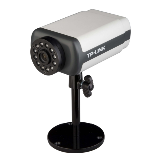
Chapter 2 Physical Overview 2.1 Front View Focus Adjustment Ring Built-in Microphone Figure 2-1 Focus Adjustment Ring: Adjust the focus to get a clear image. Built-in Microphone: Built-in microphone for two-way audio. 2.2 Bottom view Audio In Audio Out Power Connector Network Connector Reset I/O Terminal Connector... - Page 9 then press and hold the Reset Button for at least 10 seconds. The CPU of the camera starts to work completely 1 minute after you release the Reset button. I/O Terminal Connector: Input/Output to support External Alarm and Sensor used for motion detection, event triggering and alarm notification, etc.
-
Page 10: Chapter 3 Using Ip Camera Via Web Browser
Chapter 3 Using IP Camera via Web Browser 3.1 Obain the IP Address Insert the provided CD into your CD-ROM driver. The Setup Wizard will automatically pop up on your computer’s screen as shown in the figure below. Figure 3-1 Choose the Intelligent IP Installer, and then the next screen appears. - Page 11 Figure 3-2 After the installation is finished, click Start > Program Files > TP-LINK >Intelligent IP Installer to start using the program. Figure 3-3 The following screen will then display. Click the Search button to search Network Cameras in the network; it displays Network Cameras information including IP Address.
-
Page 12: Windows Web Browser
Figure 3-4 3.2 Windows Web Browser Click Link to IE button in Figure 3-4 or launch your web browser, and enter the IP address (obtain from Figure 3-4) of the IP camera in the Location / Address field of your browser. Note: For the first time login with IE, you will need to enable “Download signed ActiveX controls”. - Page 13 Figure 3-5 Note: The default User name “admin” and Password “admin” are set at the factory for the administrator. You can change them in the Account Menu. (Please check “SETTING → BASIC → Security → Account”) The web-based management page will display on your screen. On the leftmost column of the web-based management page are Setting, Client Setting, and Image Setup.
-
Page 14: Mac Web Browser
3.3 Mac Web Browser Click the Safari icon on the screen as the figure below shown, and enter the IP address of the IP camera (which can be obtained from Figure 3-4) in the Location / Address field of your browser. - Page 15 Enter the default User name “admin” and password “admin” in the dialog box as shown below. Figure 3-8 Note: The default Name “admin” and Password “admin” are set at the factory for the administrator. You can change them in the Account Menu (Please check “SETTING → BASIC → Security → Account”).
- Page 16 The web-based management page will be display on your screen. In the leftmost column of the web-based management page are Setting, Client Setting, and Image Setup. For more details, you can refer to Section 5.2、Section 5.3 and Section 5.4. Figure 3-9...
-
Page 17: Chapter 4 Using Ip Camera Via Mobile Phone
Using IP Camera via Mobile Phone You can use TP-LINK Web User Interface via mobile phones. To use IP cameras via mobile phones, please make sure your RTSP is set to “On” (Default is “On”). To change the settings of IP cameras, Please check “Settings →... - Page 18 Below is an example of viewing the camera in 3G streaming mode on NOKIA N76: 1. Click Function and select Gallery. 2. Click the Streaming links. 3. Click Option and add a New link 4. Type the New link Name and Web address. (The address is Public IP or domain name), Ex: rtsp://tl-sc3171.dyndns.org/video.3gp...
-
Page 19: Web Brower Mobile View Mode
5. Open with Real-Player and click Yes to connect. 4.2 3G Web Brower Mobile View Mode For 3G Web Browser Mobile View Mode, please type “http://<IP>” into your 3G Mobile’s Web Browser. <IP> is the Public IP address of your IP camera (the default value is 192.168.1.100); For Example: rtsp://192.168.1.100:554/video.3gp Below is an example of viewing the camera in 3G Web Browser Mobile View Mode on iPhone 3G: Select Safari function... - Page 20 Enter name and password. Default The TP-LINK User Interface and live values are both admin. Then click Log image will show up in the middle of the screen. Note: It will show continuous snapshots not a real time video streaming. Therefore, the recording...
-
Page 21: G Wap Browser Snapshot Mode
To use IP Camera via HP PDA, please take the following steps: 1. For HP iPDA HSTNH-L05C-WL, you need to install the free software Platform4 Player first. Click the program Platform4 Player. 2. Click the setting and type rtsp link in Open Url field. Ex: rtsp://tl-sc3171.dyndns.org/video.3gp... - Page 22 3. Click Setting I and select protocol with TCP. 4. Click Setting II and select System Settings. 5. Click OK and connect to IP Camera.
- Page 23 To use IP Camera via Opera Mobile with Windows Mobile Smart Phone, please take the following steps: 1. Download the ”Opera Mobile 9.5.cab“ and copy to Windows Mobile 6 Smart Phone. 2. Click the “Windows Explorer” to find the download cab file. 3.
- Page 24 5. Type IP or http url link. 6. Type the username and password or setup authentication off in Setting > Basic > Security > Account.
-
Page 25: Chapter 5 Configuration Of Main Menu
Chapter 5 Configuration of Main Menu You would find that the illustrative web pages in this Manual are all orange. Please note that they're from our latest firmware, which can be downloaded from our website. Web pages in our previous firmware are blue. -
Page 26: Zoom In / Out The Image Via The Monitor Window
5.1.2 Zoom in / out the image via the monitor window Click to display the digital zoom in window. Pull the to adjust the digital zoom range, and it will be showed on the above window. You can use the left click of your mouse to move the to any where on the window to view the desired detail more clearly. -
Page 27: Setting
Microphone turned off Volume control bar 5.2 Setting This function is only for the Administrator. Click this button to get into the Basic and Advance settings menus. There are four sub-menus under the BASIC menu, which includes System, Camera, Network, and Security. -
Page 28: Mode
Click this button to configure the settings of IP Camera, which includes Mode, View Size, Protocol, and Video Buffer. 5.3.1 Mode Click the drop-down list to choose MPEG4, MJPEG and JPEG video compression mode. Note: MJPEG streaming is unavailable if RTSP mode is On (Please check SETTING → BASIC → Camera →... -
Page 29: Video Buffer
General). 5.3.4 Video Buffer Turn the Video Buffer function ON / OFF. The Video Buffer function makes the streaming more smoothly in unsteady network environment, but might cause a little delay in live viewing. 5.4 Image Setup You can use the tool bar to optimize video Brightness, Contrast, Saturation and Hue. 5.4.1 Brightness The higher value the brightness is, the brighter the image is. -
Page 30: Chapter 6 Setting-Basic
Chapter 6 Setting-BASIC Click BASIC to display the submenus including System, Camera, Network, and Security. 6.1 System Click System to display the submenus including Information, Date/Time, and Initialize. 6.1.1 Information The Information page provides the basic information of the product which includes Product Name, Firmware Version and Web Version. -
Page 31: Date/Time
6.1.2 Date/Time The Date/Time page displays all options of time setting. Current date/time: Displays the current date and time of this IP Camera. PC clock: Displays the date and time of the monitoring PC clock. Date/time format: You can click the drop-down list to select different time display formats. Adjust: You can select one of those four adjusting modes for your IP Camera. -
Page 32: Initialize
Note: The NTP server (Network Time Protocol) is the time server which is an Internet standard protocol built on the top of TCP / IP. This assures accurate synchronization to the millisecond of computer clock time in a network of computers. Time zone: You can select the format from Greenwich Mean Time. -
Page 33: Camera
applied immediately. The default language is “English”. 6.2 Camera Click Camera to display the submenus including General, MPEG4 and MJPEG. 6.2.1 General RTSP: Switch is On or Off RTSP Port: Specify the transmission port number of RTSP streaming. The default value is 554. Port Range: Specify the transmission port range of RTP streaming video. -
Page 34: Mpeg4
randomly from this range. Note: RTSP (Real Time Streaming Protocol) is a protocol used in streaming media system which allows clients to remotely control a streaming video server. RTSP is supports by most of the media clients such as Real Player, QuickTime and VLC...etc. Image rotated: You can mirror or flip the display screen. - Page 35 Viewer Authentication: If the viewer authentication is On, the users will be requested to type in username and password when viewing through RTSP. Multicast Streaming (If it is ON) Multicast address: Specify the multicast server address. Video/Audio port: Specify the transmission port number of the video data, which is an even number from 1024 to 65534.
- Page 36 B. Mobile View If RTSP is On (see Setting →Basic → Camera → General), the screen will display as shown below. Viewer Authentication: If the viewer authentication is On, the users will be requested to type in username and password when viewing through RTSP. Multicast Streaming (If it is On) Multicast Address: Specify the multicast server address.
-
Page 37: Mjpeg
through. Image Size: The image size of Mobile View is fixed at 160 x 120. Frame Rate: Set the frame rate of the MPEG4 image. You can choose values from 5, 10fps. The unit “fps” stands for “frames sent per second”. Quality: Auto: The quality and bitrate will be adjusted automatically according to the frame rate. -
Page 38: Network
If RTSP is Off (see Setting →Basic → Camera → General), the screen will display as shown below. Image Size: Specify the image size when the network camera transmits. You can choose among 640 x 480, 320 x 240, and 160 x 120. Frame Rate: Set the frame rate of the MJPEG image. -
Page 39: Information
6.3.1 Information The page of Information displays the MAC address of the device. Obtain an IP address automatically (DHCP): (If a DHCP server is installed on the network) Select this, the IP will be assigned by the DHCP serve. Obtain DNS server address automatically: Select this to obtain the address of DNS server automatically. - Page 40 Use the following IP address: Select this when the fixed IP address is set. IP address: Enter the IP address of the device. Subnet mask: Enter the subnet mask. Default gateway: Enter the default gateway. Use the following DNS server address: Select this when you set the fixed IP address as the IP address of DNS server.
-
Page 41: Pppoe (Point-To-Point Protocol Over Ethernet)
6.3.2 PPPoE (Point-to-Point Protocol over Ethernet) If your ISP provides Dynamic IP with authentication by username and password, enter all PPPoE information in this part. When you use the PPPoE function, you need to turn on the DDNS or IP Notification function at the same time. -
Page 42: Ddns (Dynamic Dns)
Use the following DNS server address: Select this when you set the fixed IP address as the IP address of DNS server. Primary DNS server: Enter the IP address of the primary DNS server. Secondary DNS server: Enter the IP address of the secondary DNS server. Note: PPPoE (Point-to-Point Protocol over Ethernet): PPPoE is a network protocol for encapsulating Point-to-Point Protocol frames insider Ethernet frames. - Page 43 The IP Camera offers the DDNS (Dynamic Domain Name System) feature, which allows the hosting of a website, FTP server, or e-mail server with a fixed domain name (named by yourself) and a dynamic IP address, and then your friends can connect to your server by entering your domain name no matter what your IP address is.
- Page 44 Input all information and follow step by step with DynDNS. Log in with new account and click Account → My Hosts → Add Host Services.
- Page 45 Type domain in the Hostname field and select sub-domain. After typing in information, check your DDNS service.
-
Page 46: Upnp (Universal Plug And Play)
Type your DDNS User ID, Password and Host name in Setting → Basic → Network → DDNS. After completing setting, reboot IP Camera. 6.3.4 UPnP (Universal Plug and Play) Choose menu “Network→UPnP”, you can view the information about UPnP (Universal Plug and Play) in the screen as shown in the following figure. -
Page 47: Bonjour
HTTP port: Enter the HTTP port number and the default HTTP port is 80. SSL port: Enter the SSL port number and the default SSL port is 443. MPEG4 RTSP port: Enter the MPEG4 RTSP port, default value is 5544. Note: UPnP (Universal Plug and Play): UPnP is a set of computer network protocol. -
Page 48: Ip Notification
Device Name: Enter Device Name to your needs. Note: How to use Bonjour in your Windows Browser UI? Please check the link below: http://www.apple.com/support/downloads/bonjourforwindows.html 6.3.6 IP Notification When network notify type is set to “ON”, you can send an e-mail notification of the completion of the network setting. -
Page 49: Messenger
e-mail is sent. If this option is selected, the IP Notification page will be different as following figure shown. POP server name: It is necessary when the POP before SMTP is selected in Authentication. Type the POP (receiving mail) server name up to 64 characters, or type the IP address of the POP server. - Page 50 Messenger: Check the radio button before On, so you can use your IP Camera via this function. Protocol: Displays the protocol used. Login Account: Enter the MSN account registered for you IP Camera. Password: Enter the password of the MSN account. Re-type password: Type the password again.
- Page 51 Configuring your IP camera Note: If you use a Modem Router to access the Internet, you should set your IP Camera as the virtual server with port range 20000-21000 on the Modem Router’s web-based management page. Click “BASIC->Network->Messenger” to enter the “Messenger” page. Enable Messenger and then set the Login Account, Password, Alias, Port range, IP Notification, Privacy and Allow list parameters as the above figure shows.
- Page 52 Make sure the MSN view plugin is installed. This plugin is embedded in IntelligentIPInstallerSetup(TPLink)-1.1.16.09.exe and will be installed automatically when you install IntelligentIPInstallerSetup(TPLink)-1.1.16.09.exe. ▲ You can download the IntelligentIPInstallerSetup(TPLink)-1.1.16.09.exe here: http://www.tp-link.com/download/ipcamera/Intelligent_IP_Installer.rar Log into your MSN account. Add the camera’s MSN account as a contact.
- Page 53 Check its status. Normally it should be online. Click the camera icon and select View a contact’s webcam to view the video.
-
Page 54: Security
Wait for a moment, and you will see the video captured by your IP Camera. 6.4 Security Click Security to display the submenus including Account and HTTPS. -
Page 55: Account
6.4.1 Account The device default account and password setting is “admin / admin”. That means everyone who knows IP address can access the device including all configuration. Therefore, it is necessary to assign a password if the device is intended to be accessed by others. User name: Set a user name between 4-16 characters. -
Page 56: Https
The Viewer mode only can view the Live View. Viewer Authentication: Allows all viewers directly access to Live View. 6.4.2 HTTPS HTTPS is a URL scheme used to indicate a secure HTTP connection. It is syntactically identical to the http:// scheme normally used for accessing resources using HTTP. Using https: //URL/ with a different default TCP port (443) and an additional encryption / authentication layer between the HTTP and TCP, you can use the IP camera through HTTPS easily by using “https://”... - Page 57 Note: When enable HTTPS with RTSP on mode, the IP Camera only protect the setting such as username and password and do not protect video and audio. When enable HTTPS with RTSP off mode, the IP Camera will protect all setting including video and audio.
-
Page 58: Chapter 7 Setting-Advance
Chapter 7 Setting-Advance Click Advance to display the submenus including FTP client, SMTP, HTTP event, Alarm output, Schedule, Alarm input, Alarm buffer, Motion detection and System Log. 7.1 FTP client Use this menu to set up for capturing and sending images to an FTP server. By using FTP client function, you can send the image and video file which has been shot and recorded linked with the built-in motion detection function to FTP server. -
Page 59: General
7.1.1 General Select On when you use FTP function. The FTP client setting page will appear. Select Off when you do not wish to use the FTP client function. Note: The frame rate and operability on the main viewer may decrease while a file is being transmitted by the FTP client function. - Page 60 Remote path: Type the path to the destination in FTP server up to 64 characters. Image file name: Type the file name you want to assign to the images when sending to the FTP server. You can use up to 10 alphanumeric characters, - (hyphen) and _ (underscore) for naming. Suffix: Select a suffix to add to the file name Date Time: The date time suffix is added to the Image file name.
- Page 61 Note: You can set motion detection on motion detection page (Please go to “Setting → Advance →Motion detection → Setting”). For more details, you can check Section 7.7. Motion Detection works only when the MPEG4 function is On and the Cropping is set to Off. Use Alarm Buffer: Select Use alarm buffer when you forward the image and video of before and after the alarm detection (pre-alarm, post-alarm).
- Page 62 Note: You can set the alarm buffer function at Alarm Buffer page (Please go “Setting→ Advance → Alarm Buffer → Setting”). For more details, you can check Section 7.7. Alarm Input: Select the connected alarm. Sensor input1: The external sensor which is connected to sensor input1 of the alarm input.
-
Page 63: Periodical Sending
Note: You can set schedule function on Schedule page. (Please go to “Setting → Advance → Schedule → Setting”) For more details, you can check Section 7.5. 7.1.3 Periodical sending You can set to send an image file to FTP server periodically by selecting On to send the image file to FTP server linked with setting period. -
Page 64: Smtp
to the file name. Sequence number: A consecutive number is added to the Image file name. Sequence number clear: Click Clear and the suffix of the sequence number returns to 1. Interval: Set the periodical sending is effective interval. Min value is 1 min and Max value is 24 hour. Effective period: Set the period when the periodical sending is effective. -
Page 65: General
7.2.1 General Select On when you use the SMTP function. The common setting options are displayed below. Select Off if you do not wish to use the e-Mail (SMTP) function. Note: The Setting of General will be the same as the setting of IP Notification (Please check “SETTING → BASIC →... - Page 66 SMTP server name: Type the SMTP server name up to 64 characters, or the IP address of the SMTP server. SMTP Server Port: You can set port number from 1~65535 according to your mail server. The default value is 25. Security setting: Check SSL box if the mail server you use has security restriction.
- Page 67 SMTP: Select it if SMTP authentication is necessary when an e-mail is sent. POP before SMTP: Select if POP before SMTP authentication is necessary when an e-mail is sent. Note: When you set to On, be sure to select either or both SMTP or / and POP before SMTP. POP server name: When the POP before SMTP is selected in Authentication, type the POP (receiving mail) server name up to 64 characters, or type the IP address of the POP server.
-
Page 68: Alarm Sending
characters.) 7.2.2 Alarm sending Set to send the mail with connection to the alarm detection by the external sensor input or by the built-in motion detection function. Select On to send the image and file to SMTP server linked with the alarm detection. - Page 69 Alarm Motion Detection: Click it for using Motion Detection function as a sensor. You can set motion detection function on the motion detection page.
- Page 70 Note: You can set motion detection on motion detection page (Please go to “Setting → Advance →Motion detection → Setting”). For more details, you can check Section 7.8. Motion Detection works only when the MPEG4 function is On and the Cropping is set to Off. Use Alarm Buffer: Select Use alarm buffer when you forward the image and video of before and after the alarm detection (pre-alarm, post-alarm).
- Page 71 Note: You can set the alarm buffer function at Alarm Buffer page (Please go “Setting→ Advance → Alarm Buffer → Setting”). For more details, you can check Section 7.7. Alarm input: Select the connected alarm. Sensor input1: The external sensor which is connected to sensor input1 of the alarm input.
-
Page 72: Periodical Sending
Note: You can set schedule function on Schedule page. (Please go to “Setting → Advance → Schedule → Setting”) For more details, you can check Section 7.5. 7.2.3 Periodical sending You can set to send an image file by SMTP server periodically by selecting On to send the image file by SMTP server linked with setting period. -
Page 73: Http Event
is added to the file name. Sequence number: A consecutive number is added to the Image file name. Sequence number clear: Click Clear and the suffix of the sequence number returns to 1. Interval: Set the periodical sending is effective interval. Minimum value is 30 min and Maximal value is 24 hour. -
Page 74: General
7.3.1 General HTTP event: Set up the HTTP server URL, port, User ID, Password, and Proxy Server settings. -
Page 75: Alarm Sending
For example: URL: 192.168.1.7/cgi-bin/operator/ptzset Note: The setting of URL should be the same as CGI. 7.3.2 Alarm sending Set to send the mail with connection to the alarm detection by the built-in motion detection function. Select On to send the image and audio file to HTTP server linked with the alarm detection. Alarm sending: Select On to set to send command with connection to the alarm detection. - Page 76 Parameter: the parameter of CGI (defined in Setting → Advance → HTTP event → General → URL) is from your target device. For example, move=down. Message: message will show up in the form of Message = PTZ down. If your target device didn’t support the parameter of message, you can’t see the message.
-
Page 77: Alarm Output
Note: You can set the alarm input function at alarm input page (Please go “Setting → Advance → Alarm input → Setting”). For more details, you can check Section 8.6. Effective period: Set the period when the periodical sending is effective. Always: The periodical sending is always effective. -
Page 78: Setting
7.4.1 Setting Alarm output: To activate the Alarm output function, select On. When you do not use the Alarm output function, select Off. Digital output: Select High signal output and Low signal output as your alarm. Trigger condition: Select the mode of the Alarm output function. You can choose “Alarm” or “Timer”. - Page 79 Note: You can set motion detection on motion detection page (Please go to “Setting → Advance →Motion detection → Setting”). For more details, you can check Section 7.7. Motion Detection works only when the MPEG4 function is On and the Cropping is set to Off. Use Alarm Buffer: Select Use alarm buffer when you forward the image and video of before and after the alarm detection (pre-alarm, post-alarm).
- Page 80 Note: You can set the alarm buffer function at Alarm Buffer page (Please go “Setting→ Advance → Alarm Buffer → Setting”). For more details, you can check Section 7.7. Alarm Input: Select the connected alarm. Sensor input1: The external sensor which is connected to sensor input1 of the alarm input.
-
Page 81: Schedule
Schedule: You can specify the period when the periodical sending is effective in the Schedule setting in the other section. Note: You can set schedule function at schedule page. (Please go “Setting → Advance → Schedule → Setting”) For more details, you can check Section 7.5. -
Page 82: Setting
7.5.1 Setting 102) Schedule Selection: Select the list box to specify the schedule you want to set. FTP -Alarm FTP - Periodical e-Mail (SMTP) -Alarm e-Mail (SMTP) -Periodical HTTP event -Alarm 103) Mon (Monday) to Sun (Sunday): The time period on the right of the checked day is the effective period of the schedule. -
Page 83: Setting
7.6.1 Setting 106) Sensor input 1: Click it on for using external sensor which is connected to sensor input1 of the camera I / O port. Trigger condition: Select High signal output and Low signal output as your alarm. Camera move: Pull down the window to select the camera preset position. 7.7 Alarm buffer You can set the Pre-alarm image and audio (the image and audio before the alarm detection) and the Post - alarm image and audio. -
Page 84: Setting
7.7.1 Setting Alarm buffer: The basic setting options are displayed below. 107) Recording capacity Pre-alarm period: Display the maximum recording capacity of image/audio before the alarm detection. Post-alarm period: Display the maximum recording capacity of image/audio after the alarm detection. 108) Recording time: Set the recording time for the Pre-alarm image/audio and Post alarm image/audio. - Page 85 There are three Motion Detection functions as sensors to set for different detecting zones. Each one has Threshold and Sensitivity inputs which you can adjust to specific zone sequentially. Motion Detection function can support FTP, SMTP and HTTP event for capturing and sending images.
-
Page 86: Setting
7.8.1 Setting 109) Threshold: It means the extent which the alarm will be triggered. 110) Sensitivity: It means that how often the sensor will scan the image. The higher sensitivity it is and the more frequently it scans. Motion Detection 1: Click it for using Motion Detection 1 function as a sensor. You can adjust and move the detecting zone by using mouse. -
Page 87: Setting
“*** ffmpeg”, “*** mjpeg”, “*** gsm” or “*** boa” will be shown in system log. In this case, please send the file “backup” to TP-LINK ( you can save it from Setting > Basic > System > Initialize > Backup setting data), and also provide the router spec you’re using, we will analyze and solve the problem as... -
Page 88: Appendix
Appendix APPENDIX a – FRAME RATE & BIT RATE TABLE This chapter provides tables that help you to optimize your IP camera with your network environment. Base on your network upload environment to choose the best Image-Quality setting. For example, if the network environment is ADSL 256Kb(upload) / 2Mb(download), the most fluent Image-Quality needs to set up under 256 Kb situation. - Page 89 320*240 320*240 160*120 1024 160*120 1024 160*120 160*120 160*120 160*120 A.3 MJPEG @ 15fps / kbps Quality 640*480 320*240 160*120 Excellent 4000 1500 Detailed 2400 Good 1600 Standard 1300 Medium A.4 MJPEG / kbps, fps Frame-Rate Current Image-Size Quality Setting Current Bitrate Setting Frame-Rate...
- Page 90 320*240 Good 320*240 Medium 160*120 Medium 160*120 Excellent 160*120 Excellent 160*120 Good 160*120 Good 160*120 Medium 160*120 Medium APPENDIX b – STORAGE REQUIREMENT TABLE This chapter provides tables that help you set your recording storage system. Please refer to the following table to find out the capability for recording into your hard disk. B.1 MPEG4 Storage Requirement GB / channel / day @ 30fps Quality 640*480...
- Page 91 B.3 MPEG4 Storage Requirement GB / channel / day Image-Size Bitrate Setting Frame-Rate Setting Current Bitrate 640*480 2048 23.0 640*480 2048 22.2 640*480 1536 18.5 640*480 1536 17.9 640*480 1024 10.5 640*480 1024 10.5 640*480 640*480 320*240 1536 15.8 320*240 1536 16.9 320*240...
-
Page 92: Faq
Q1. What can I do if I forgot the login name and password? Press and hold the Reset button on the bottom panel with a pin or paperclip. Please continue holding down the Reset button for approximately 15 seconds. And then IP Camera will reboot. It will require 45 seconds.