Table of Contents
Advertisement
Quick Links
Download this manual
See also:
User Manual
Advertisement
Table of Contents

Related Manuals for Vaisala WXT510


Summary of Contents for Vaisala WXT510
- Page 1 Weather Transmitter WXT510 UIDE M210470EN-B October 2004...
- Page 2 The contents are subject to change without prior notice. Please observe that this manual does not create any legally binding obligations for Vaisala towards the customer or end user. All legally binding commitments and agreements are included exclusively in the applicable supply contract or...
-
Page 3: Table Of Contents
Safety..................7 Trademarks ................9 License Agreement ..............9 Warranty ..................9 CHAPTER 2 PRODUCT OVERVIEW................10 Weather Transmitter WXT510 ..........10 Configuration software ............10 Heating function ..............10 WXT510 Transmitter components ........11 CHAPTER 3 FUNCTIONAL DESCRIPTION..............12 Wind measurement principle .......... - Page 4 User's Guide _______________________________________________________________________ Wiring by using the 8-pin M12 connector (optional)...24 CHAPTER 6 COMMUNICATION SETTINGS..............26 Communication protocols .............26 PC connection.................27 Screw terminal/M12 connection ..........27 Service port connection ............27 Communication setting commands........28 Checking the current communication settings (aXU) ..28 Setting fields ................29 Changing the communication settings ........30 CHAPTER 7 GETTING THE DATA MESSAGES..............32...
- Page 5 CHAPTER 9 MAINTENANCE ................... 79 Cleaning .................. 79 Replacing the PTU module............ 79 Factory calibration and repair service ......... 80 Vaisala Service Centers............80 CHAPTER 10 TROUBLESHOOTING ................. 81 Self-diagnostics..............83 Error messaging/Text messages ........83 Rain and wind sensor heating control ......... 84 Operating voltage control ............
- Page 6 User's Guide _______________________________________________________________________ Wiring...................91 Communication protocol............91 RS-485 serial interface ............92 Wiring...................92 Communication protocol............92 WXT ASCII, polled...............92 NMEA 0183 v3.0, query ............93 NMEA 0183 v3.0 query with ASCII query commands..95 APPENDIX B SDI-12 PROTOCOL..................97 APPENDIX C CRC-16 COMPUTATION ................100 Encoding the CRC as ASCII Characters......100 NMEA 0183 v3.0 Checksum computation ......101 6 ____________________________________________________________________ M210470EN-B...
-
Page 7: Chapter 1 General Information
CHAPTER 1 GENERAL INFORMATION Feedback Vaisala Customer Documentation Team welcomes your comments and suggestions on the quality and usefulness of this publication. If you find errors or have other suggestions for improvement, please indicate the chapter, section, and page number. You can send comments to us by e-mail: manuals@vaisala.com... -
Page 8: Product Related Safety Precautions
User's Guide _______________________________________________________________________ Product Related Safety Precautions The WXT510 delivered to you has been tested for safety and approved as shipped from the factory. Note the following precautions: WARNING Ground the product, and verify outdoor installation grounding periodically to minimize shock hazard. -
Page 9: Trademarks
Microsoft Corporation in the United States and/or other countries. License Agreement All rights to any software are held by Vaisala or third parties. The customer is allowed to use the software only to the extent that is provided by the applicable supply contract or Software License Agreement. -
Page 10: Chapter 2 Product Overview
WXT510 powers up with 5...30 VDC and outputs serial data with a selectable communication protocol: SDI-12, ASCII automatic & polled and NMEA 0183 with query option. Four alternative serial interfaces are selectable: RS-232, RS-485, RS-422 and SDI-12. -
Page 11: Wxt510 Transmitter Components
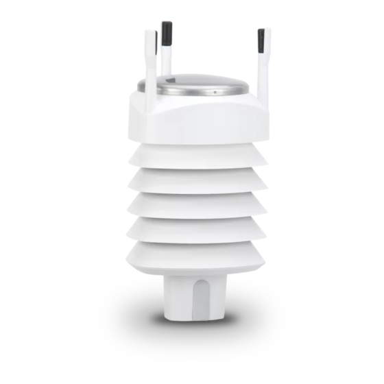
Chapter 2 ___________________________________________________________ Product Overview WXT510 Transmitter components Wind transducers Top of the Precipitation sensor transmitter Pressure sensor Radiation shield module Humidity/temperature sensor Bottom of the Screw cover transmitter Bottom of the transmitter Service port Radiation shield Cable gland (water tight) -
Page 12: Functional Description
CHAPTER 3 FUNCTIONAL DESCRIPTION Wind measurement principle â The WXT510 uses Vaisala WINDCAP sensor technology in wind measurement. The wind sensor has an array of three equally spaced ultrasonic transducers on a horizontal plane. Wind speed and wind directions are determined by measuring the time it takes the ultrasound to travel from each transducer to the other two. -
Page 13: Precipitation Measurement Principle
The wind speed is represented as a scalar speed in selected units (m/s, kt, mph, km/h). The wind direction is expressed in degrees ). The wind direction reported by WXT510 indicates the direction that the wind comes from. North is represented as 0 , east as 90 , south as 180 , and west as 270 . -
Page 14: Ptu Measurement Principle
User's Guide _______________________________________________________________________ - Polled mode: Transmitter sends a precipitation message whenever requested by the user. More information about the precipitation sensor operation modes is found on page 71. PTU measurement principle PTU module contains separate sensors for pressure, temperature, and humidity measurement. - Page 15 Chapter 3 _______________________________________________________ Functional Description High limit (+ 3 C/ 37.4 F) Middle limit (-2 C /28.4 F) Low limit (-4 C/ 24.8 F) VAISALA________________________________________________________________________ 15...
-
Page 16: Chapter 4 Installation
WARNING To protect personnel (and the device), a lightning rod should be installed with the tip at least one meter above the WXT510. The rod must be properly grounded, compliant with all local applicable safety regulations. 16 ___________________________________________________________________ M210470EN-B... -
Page 17: Assembling The Wxt510
Protective cap Fixing screw (3 pcs) Installation Procedure At the measurement site, WXT510 needs to be mounted, aligned, and connected to the data logger and the power source. Mounting Weather Transmitter WXT510 can be mounted either onto a vertical pole mast or onto a horizontal cross arm. When mounting WXT510 onto a pole mast, an optional mounting kit can be used to ease mounting. -
Page 18: Mounting To A Vertical Pole Mast
Weather Transmitter WXT510 must be installed to an upright, vertical position. Mounting to a vertical pole mast 1. Remove the screw cover and insert the WXT510 to the pole mast. 2. Align the transmitter in such a way that the arrow points to north, see page 20. -
Page 19: Mounting To A Horizontal Cross Arm
Chapter 4 ________________________________________________________________ Installation Turn firmly until adapter is locked. Insert the mounting adapter. Mounting kit (optional) Pole mast Fixing screw (provided) Mounting to a horizontal cross arm 1. Remove the screw cover. 2. Align the horizontal cross arm in south-north-direction, see page In case the cross arm cannot be aligned, make the wind direction correction as instructed on page 21. -
Page 20: Aligning The Wxt510
Compass Alignment To align Weather Transmitter WXT510, proceed as follows: 1. If the WXT510 is already mounted, loosen the fixing screw on the bottom of the transmitter so that you can rotate the device. 2. Use a compass to determine that the transducer heads of WXT510 are exactly in line with the compass and that the arrow on the bottom of WXT510 points to the north. -
Page 21: Wind Direction Correction
3. Feed the deviation angle to the device by using the wind message formatting command aWU, D (direction correction), see page 64. 4. From now on, the WXT510 transmits the wind direction data by using the changed zero-alignment. NORTH... -
Page 22: Chapter 5 Wiring
Only one serial interface can be used at a time. Power supplies Operating power Vin for both unheated and heated WXT510: 5...30 VDC (average power consumption 1 mW...400 mW) The power consumption varies with different operating modes and input voltages, see Chapter 11. The consumed current may be as low as 0.07 mA in SDI-12 idle mode @12 V (with heating function... -
Page 23: Wiring By Using The Screw Terminals
Make sure that you connect only de-energized wires. Wiring by using the screw terminals Loosen the three long screws at the bottom of the WXT510. Pull out the bottom part of the transmitter. Insert the power supply wires and signal wires through the cable gland(s) in the bottom of the transmitter. -
Page 24: Wiring By Using The 8-Pin M12 Connector (Optional)
User's Guide _______________________________________________________________________ Table 1. Screw Terminal Pin-outs for WXT510 Serial Interfaces and Power Supplies. Screw RS-232 RS-485 RS-422 SDI-12 Terminal Pin 1 RX- Data- Data in (RX-) 2 RX+ Data+ Data in (RX+) 3 TX- Data out (TxD) Data-... - Page 25 The pin connections for the 8-pin M12 connector and the wire colors of the respective M12 cable (optional, 2/10 m) are listed in the following Table 2. Table 2. Pin-outs for WXT510 Serial Interfaces and Power Supplies. Wire Colors M12 Pin #...
-
Page 26: Communication Settings
User's Guide _______________________________________________________________________ CHAPTER 6 COMMUNICATION SETTINGS Communication protocols As soon as the WXT510 has been properly connected and powered the data transmission can be started. The communication protocols available in each of the serial interfaces are shown in the following table. -
Page 27: Pc Connection
(see picture on page 11) by using a service cable. 2. Power-up the WXT510 by using a 9V alkaline in connection with the service cable or by using the screw terminals/M12 connector. -
Page 28: Communication Setting Commands
Communication setting commands Checking the current communication settings (aXU) With this command you can request the current communication settings of the WXT510. aXU<cr><lf> Command format in and NMEA 0183: ASCII aXXU! -
Page 29: Setting Fields
Defines the delay between the last character of the query and the first character of the response message from the WXT510. During the delay, the line is not reserved. Effective in ASCII, polled and NMEA 0183 query protocols. Effective when RS- 485 is selected (C=3). -
Page 30: Changing The Communication Settings
User's Guide _______________________________________________________________________ Example (ASCII and NMEA 0183, device address 0): 0XU<cr><lf> 0XU,A=0,M=P,T=0,C=2,B=19200,D=8,P=N,S=1,L=25,N=WXT510,V= 1.00<cr><lf> Example (SDI-12, device address 0): 0XXU! 0XXU,A=0,M=S,T=0,C=1,B=1200,D=7,P=E,S=1,L=25,N=WXT5 10,V=1.00<cr><lf> Changing the communication settings Make the desired setting with the following command. Select the correct value/letter for the setting fields, see page 29. See also the examples. - Page 31 Chapter 6 ______________________________________________________ Communication settings NOTE Reset the transmitter to validate the changes of communication parameters by disconnecting the service cable or using the Reset command, page 32. Example (ASCII and NMEA 0183, device address 0): Changing the device address from 0 to 1: 0XU,A=1<cr><lf>...
-
Page 32: Getting The Data Messages
User's Guide _______________________________________________________________________ CHAPTER 7 GETTING THE DATA MESSAGES The general commands and data message commands are presented in this chapter. Each communication protocol has an own section for data message commands. For changing the message parameters, units and other settings, see Chapter 8, Sensor and data message settings. -
Page 33: Precipitation Counter Reset (Axzru)
Chapter 7 ___________________________________________________ Getting the data messages 0XZ! 0 (No response is obtained in SDI-12 protocol. Example (NMEA 0183): <cr><lf> $WITXT,01,01,07,Start-up*29 Precipitation counter reset (aXZRU) This command is used to reset the precipitation sensor counters. aXZRU<cr><lf> Command format in ASCII and NMEA 0183: aXZRU! Command format in SDI-12: where... -
Page 34: Measurement Reset (Axzm)
User's Guide _______________________________________________________________________ Measurement reset (aXZM) This command is used to interrupt all ongoing measurements of the transmitter and start them from the beginning. Command format in ASCII and NMEA 0183: aXZM<cr><lf> aXZM! Command format in SDI-12: where Device address (default= 0) = Measurement break command <cr><lf>... -
Page 35: Ascii Protocol, Polled (Without Crc)
Chapter 7 ___________________________________________________ Getting the data messages ASCII protocol, polled (without CRC) This section presents the data commands and data message formats for the ASCII communication protocols. NOTE Type commands in CAPITAL letters. Abbreviations and units For changing the units, see chapter 8 Sensor and data message settings. -
Page 36: Device Address (?)
User's Guide _______________________________________________________________________ Device address (?) This command is used to query the address of the device on the bus. ?<cr><lf> Command format: where Device address query command <cr><lf> = Command terminator The response: b<cr><lf> where Device address (default=0) <cr><lf> Response terminator. -
Page 37: Wind Data Message (Ar1)
Chapter 7 ___________________________________________________ Getting the data messages Wind data message (aR1) With this command you can request the wind data message. aR1<cr><lf> Command format: where Device address (default = 0) Wind message query command <cr><lf> Command terminator Example of the response (the parameter set is configurable): 0R1,Dn=236D,Dm=283D,Dx=031D,Sn=0.0M,Sm=1.0M,Sx=2.2M<cr><... -
Page 38: Precipitation Data Message (Ar3)
User's Guide _______________________________________________________________________ where Device address (default=0) Pressure, temperature and humidity message query command <cr><lf> Command terminator Example of the response (the parameter set is configurable): 0R2,Ta=23.6C,Ua=14.2P,Pa=1026.6H<cr><lf> where Device address Pressure, temperature and humidity query command Air temperature (C = C) Relative humidity (P = RH%) Air pressure (H = hPa) Response terminator... -
Page 39: Supervisor Data Message (Ar5)
Chapter 7 ___________________________________________________ Getting the data messages where Device address Precipitation message query command Precipitation amount (M = mm) Rain duration (s = s) Rain intensity (M = mm/h) Hail amount (M = hits/cm Hail duration (s = s) Hail intensity (M = hits/cm <cr><lf>... -
Page 40: Combined Data Message (Ar)
User's Guide _______________________________________________________________________ To change the parameters and units in the response message and to make other settings, see Chapter 8, section Supervisor message. Combined data message (aR) With this command you can request all individual messages aR1, aR2, aR3 and aR5 with just one command. aR<cr><lf>... -
Page 41: Ascii Protocol, Polled (With Crc)
Chapter 7 ___________________________________________________ Getting the data messages Example of the response (the parameters included can be chosen from the full parameter set of the commands aR1, aR2, aR3 and aR5): 0R0,Dx=005D,Sx=2.8M,Ta=23.0C,Ua=30.0P,Pa=1028.2H,Hd =0.00M,Rd=10s,Th=23.6C<cr><lf> For selecting the parameter set in the response message, see Chapter 8 Sensor and data message settings. -
Page 42: Ascii Protocol, Automatic
User's Guide _______________________________________________________________________ In every case the response contains a three character CRC before the <cr><lf>. For selecting the parameters to be included in the response messages, changing the units and making other configurations of the measured parameters, see Chapter 8, Sensor and data message settings. NOTE The correct CRC for each command can be asked by typing a command with a random three 3-character CRC. -
Page 43: Sdi-12 Protocol
Chapter 7 ___________________________________________________ Getting the data messages Example: 0R1,Dm=027D,Sm=0.1M <cr><lf> 0R2,Ta=74.6F,Ua=14.7P,Pa=1012.9H <cr><lf> 0R3,Rc=0.10M,Rd=2380s,Ri=0.0M,Hc=0.0M,Hd=0s,Hi=0.0M <cr>< lf> 0R5,Th=76.1F,Vh=11.5N,Vs=11.5V,Vr=3.510V<cr><lf> Example (with CRC): 0r1,Sn=0.1M,Sm=0.1M,Sx=0.1MGOG 0r2,Ta=22.7C,Ua=55.5P,Pa=1004.7H@Fn 0r3,Rc=0.00M,Rd=0s,Ri=0.0MIlm 0r5,Th=25.0C,Vh=10.6#,Vs=10.8V,Vr=3.369VO]T Stop the automatic output by changing the communication protocol to NOTE polled mode (aXU,M=P). SDI-12 protocol For changing the message parameters, units and other settings, see Chapter 8 Sensor and data message settings. -
Page 44: Send Identification Command (Ai)
User's Guide _______________________________________________________________________ Send identification command (aI) This command is used to the query device for the SDI-12 compatibility level, model number, and firmware version and serial number. Command format: where Device address (default = 0) Send identification command Command terminator The response: allccccccccmmmmmmvvvxxx . -
Page 45: Change Address Command (Aab)
Chapter 7 ___________________________________________________ Getting the data messages where Address query command Command terminator The response: a<cr><lf> where Device address (default = 0) <cr><lf> Response terminator Example (device address 0): ?! 0 <cr><lf> Change address command (aAb) This command changes the device address. After the command has been issued and responded to, the sensor is not required to respond to another command for one second time in order to ensure writing the new address to the non-volatile memory. -
Page 46: Start Measurement Command (Am)
User's Guide _______________________________________________________________________ Start measurement command (aM) This command asks the device to make a measurement. The measured data are not sent automatically and should be requested with a separate Send data command aD. The host device is not allowed to send any commands to other devices on the bus until the measurement is completed. -
Page 47: Start Measurement Command With Crc (Amc)
Chapter 8, Sensor and data message settings. NOTE When the measurement takes less than one second, the response part 2 is not sent. In the WXT510 this is the case in the precipitation measurement aM3. NOTE The maximum number of parameters that can be measured with aD command is 9. - Page 48 User's Guide _______________________________________________________________________ where Device address (default = 0) Start concurrent measurement command The desired measurement 1 = Wind 2 = Pressure, humidity and temperature 3 = Precipitation 5 = Supervisor If x is left out, the query refers to composite message in which the user can request data from several sensors with just one command.
-
Page 49: Start Concurrent Measurement With Crc (Acc)
Chapter 7 ___________________________________________________ Getting the data messages Start concurrent measurement with CRC (aCC) aCCx! Command format: The function of this command, the definition of x and the response structure are the same as for the Start concurrent measurement command aCx. In order to request the measured data, Send data command aD should be used, see the following sections. -
Page 50: Examples Of Am, Ac And Ad Commands
User's Guide _______________________________________________________________________ where Device address (default =0) <data fields> = The measured parameters in selected units, separated with '+' marks (or - marks in case of parameter values). <cr><lf> Response terminator NOTE aD0 command can also be used to break the measurement in progress started with commands aM, aMC, aC or aCC. -
Page 51: Continuous Measurement (Arx)
A sensor able to continuously monitor the phenomena to be measured does not require a start measurement command aM. The data can be read instantly with the command aRx. In case of the WXT510 only the precipitation data can be retrieved using continuous measurement. aRx! -
Page 52: Start Verification Command (Av)
0R3! 0+0.15+20+0.0+0.0+0+0.0<cr><lf> Start verification command (aV) This command is used to query self diagnostic data from the device. However, the command is not implemented in the WXT510. The self- diagnostic data can be requested with aM5 command. 52 ___________________________________________________________________ M210470EN-B... -
Page 53: Nmea 0183 V3.0 Protocol
Chapter 7 ___________________________________________________ Getting the data messages NMEA 0183 V3.0 protocol This section presents the data query commands and data message formats for the NMEA 0183 v3.0 Query and automatic protocols. For changing the message parameters, units and other settings, see Chapter 8, Sensor and data message settings. -
Page 54: Mwv Wind Speed And Direction Query
User's Guide _______________________________________________________________________ where <cr><lf> Command terminator The response: <cr><lf> where Device address (default = 0) <cr><lf> Response terminator Example: <cr><lf> 0 <cr><lf> MWV wind speed and direction query Request the wind speed and direction data with a MWV query command. - Page 55 Wind sensor. The checksum to be typed in the query depends on the device identifier characters. The correct checksum can be asked from the WXT510 by typing any three characters after the $--WIQ,MWV command. Example: Typing the command $--WIQ,MWVxxx<crlf> (xxx arbitrary characters) the WXT510 responds $WITXT,01,01,08,Use chksum 2F*72<crlf>...
-
Page 56: Xdr Transducer Measurement Query
Units of the first transducer measurement, see the following transducer table. c--c1 First transducer identification (id). The WXT510's address aXU,A is added as a base number to the transducer id. For changing the address, see Chapter 6, command aXU,A= [0...9/A...Z/a...z] Transducer type for the transducer n, see the following transducer table. - Page 57 Response terminator NMEA-format transmits only numbers as transducer ids. If the WXT510 address is given as a letter, it will be shown as a number (0...9, A=10,B=11, a=36, b=37 etc.). The checksum to be typed in the query depends on the device identifier characters and can be asked from the WXT510, see example below.
- Page 58 User's Guide _______________________________________________________________________ Wind direction max Wind speed min Wind speed average Wind speed min Pressure Temperature Tp temperature Humidity Rain accumulation Rain duration Rain intensity Hail accumulation Hail duration Hail intensity Heating temperature Supply voltage Heating voltage 3.5V reference voltage Example of the XDR Query (all parameters of each sensor enabled and NMEA wind formatter set to T): $--WIQ,XDR*2D<crlf>...
- Page 59 Chapter 7 ___________________________________________________ Getting the data messages The structure of the wind sensor response message: where Start of the message Talker identifier (WI=weather instrument) Transducer measurement response identifier Transducer id 0 type (min wind direction), see the following Transducer table Transducer id 0 data (min wind direction) Transducer id 0 units (degrees, min wind direction) Transducer id for min wind direction...
- Page 60 User's Guide _______________________________________________________________________ where Transducer id for Tp internal temperature Transducer id 0 type (Humidity) 50.1 Transducer id 0 data (Humidity) Transducer id 0 units (%, Humidity) Transducer id for Humidity Transducer id 0 type (Pressure) 1009.1 Transducer id 0 data (Pressure) Transducer id 0 units (hPa, Pressure) Transducer id for Pressure Checksum delimiter...
- Page 61 Chapter 7 ___________________________________________________ Getting the data messages where Start of the message Talker identifier (WI=weather instrument) Transducer measurement response identifier Transducer id 2 type (Heating temperature), see the following Transducer table 25.5 Transducer id 2 data (Heating temperature) Transducer id 2 units (C, Heating temperature) Transducer id for Heating temperature Transducer id 0 type (Heating voltage) 10.6...
-
Page 62: Txt Text Transmission
User's Guide _______________________________________________________________________ TXT text transmission These short text messages and their interpretation are shown in Error messaging /Text messages table, on page 81. The text transmission response format: $WITXT,xx,xx,xx,c--c*hh<cr><lf> where Start of the message Talker identifier (WI=weather instrument) Text transmission identifier. Total number of messages, 01 to 99 Message number. - Page 63 Chapter 7 ___________________________________________________ Getting the data messages You can use ASCII data query commands aR1, aR2, aR3, aR5, aR, aR0 and their CRC-versions ar1, ar2, ar3, ar5, ar and ar0 also in NMEA 0183 protocol. The responses to these commands will be in standard NMEA 0183 format.
-
Page 64: Sensor And Data Message Settings
User's Guide _______________________________________________________________________ CHAPTER 8 SENSOR AND DATA MESSAGE SETTINGS In this chapter the sensor configuration and data message formatting commands are presented for all communication protocols: ASCII, NMEA 0183 and SDI-12. Wind sensor Checking the settings With the following command you can check the current wind sensor settings. -
Page 65: Setting Fields
Chapter 8 _____________________________________________ Sensor and data message settings Example (ASCII and NMEA 0183, device address 0): <cr><lf> <cr><lf> 0WU,R=01001000&00100100,I=60,A=10,U=N,D=-90,N=W Example (SDI-12, device address 0): 0XWU! 0XWU,R=11111100&01001000,I=10,A=3,U=M,D=0,N=W < cr><lf> Setting fields = Parameter selection: This field consists of 16 bits defining the wind parameters included in the data messages. -
Page 66: Changing The Settings
User's Guide _______________________________________________________________________ 0183 (automatic) is sent in XDR or MWV format. <cr><lf> = Response terminator NOTE When using MWV wind messages in NMEA 0183, one of the R field's bits 1-6 must be 1. Changing the settings You can change the following settings: - Parameters included in the wind data message - Update interval - Averaging time... - Page 67 Chapter 8 _____________________________________________ Sensor and data message settings Examples (ASCII and NMEA 0183, device address 0): You need 20 seconds averaging time for average wind speed and average direction data to be available both in wind data message and composite message in every 60 seconds. Wind speed in knots and wind direction correction +10 .
-
Page 68: Pressure, Temperature And Humidity Sensors
User's Guide _______________________________________________________________________ Pressure, temperature and humidity sensors Checking the settings With this command you can check the current p ressure, temperature and sensor settings. humidity aTU<cr><lf> Command format in ASCII and NMEA 0183: aXTU! Command format in SDI-12: where = Device address (default = 0) = Pressure, temperature and humidity sensor settings ASCII and NMEA 0183... -
Page 69: Changing The Settings
Chapter 8 _____________________________________________ Sensor and data message settings The parameter order is shown in the following table: 1st bit (most left) Air pressure The bits 1-8 determine the parameters 2nd bit Air temperature included in the message obtained with the 3rd bit Internal temperature following commands:... - Page 70 User's Guide _______________________________________________________________________ Command format in ASCII and NMEA 0183: aTU,R=x,I=x,P=x,H=x<cr><lf> Command format in SDI-12: aXTU,R=x,I=x,P=x,H=x! where R, I, P, T = The pressure, temperature and humidity sensor setting fields, see page 68. value for the setting <cr><lf> Command terminator in ASCII and NMEA 0183 Command terminator in SDI-12 Examples (ASCII and NMEA 0183, device address 0):...
-
Page 71: Precipitation Sensor
Chapter 8 _____________________________________________ Sensor and data message settings Precipitation sensor Checking the settings With this command you can check the current p recipitation sensor settings. aRU<cr><lf> Command format in ASCII and NMEA 0183: aXRU! Command format in SDI-12: where = Device address (default = 0) = Precipitation sensor settings command in ASCII and NMEA 0183... -
Page 72: Setting Fields
User's Guide _______________________________________________________________________ Setting fields [R] = Parameter selection: This field consists of 16 bits defining the precipitation parameters included in the data messages. The bit value 0 disables and the bit value 1 enables the parameter. The parameter order is shown in the following table: 1st bit (most left) Rc Rain amount The bits 1-8 determine the parameters... -
Page 73: Changing The Settings
Chapter 8 _____________________________________________ Sensor and data message settings precipitation message 10 seconds after the first recognition of precipitation. Rain duration Rd increases in 10 s steps. Precipitation has ended when Ri = 0. This mode is used for indication of the start and the end of the precipitation. - Page 74 User's Guide _______________________________________________________________________ - Autosend mode - Counter reset Make the desired setting with the following command. Select the correct value/letter for the setting fields, see page 72. See the examples ! Command format in ASCII and NMEA 0183: aRU,R=x,I=x, U=x,S=x,M=x,Z=x<cr><lf> Command format in SDI-12: aXRU,R=x,I=x,U=x,S=x,M=x,Z=x! where...
-
Page 75: Supervisor Message
Chapter 8 _____________________________________________ Sensor and data message settings In SDI-12 mode a separate enquiry (0XRU!) must be given to check the data content. Supervisor message Checking the settings With this command you can check the current supervisor settings. aSU<cr><lf> Command format in ASCII and NMEA 0183: aXSU! Command format in SDI-12: where... - Page 76 User's Guide _______________________________________________________________________ 1st bit (most left) Th Heating temperature 2nd bit Vh Heating voltage The bits 1-8 determine the parameters 3rd bit Vs Supply voltage included in the message obtained with the 4th bit Vr 3.5 V reference voltage following commands: 5th bit spare...
-
Page 77: Changing The Settings
Chapter 8 _____________________________________________ Sensor and data message settings Changing the settings You can change the following settings: - Parameters included in the supervisor data message - Update interval - Error messaging on/off - Heating control Make the desired setting with the following command. Select the correct value/letter for the setting fields, see page 75. -
Page 78: Composite Message
User's Guide _______________________________________________________________________ Composite message The parameters to be included in the composite message aR0 can be defined in the parameter selection fields of each parameter (aWU,R, aTU,R, aRU,R and aSU,R). See parameter tables of each sensor in the previous sections. See the following examples. NOTE When changing the bits 9-16 of the parametrer selection of any sensor, the command can be shortened by replacing the bits 1-8 with... -
Page 79: Chapter 9 Maintenance
Cleaning To ensure the accuracy of measurement results, Weather Transmitter WXT510 should be cleaned when it gets contaminated. Leaves and other such particles should be removed from the precipitation sensor and the transmitter should be cleaned carefully with a soft, lint-free cloth moistened with mild detergent. -
Page 80: Factory Calibration And Repair Service
User's Guide _______________________________________________________________________ Factory calibration and repair service Send the device to Vaisala Instruments Service Centre for calibration and adjustment, see contact information below. Vaisala Service Centers NORTH AMERICAN SERVICE CENTER Vaisala Inc., 10-D Gill Street, Woburn, MA 01801-1068, USA. -
Page 81: Chapter 10 Troubleshooting
Chapter 10 ___________________________________________________________ Troubleshooting CHAPTER 10 TROUBLESHOOTING Data validation Problem Interpretation Action Wind measurement failure. Blockage (trash, leaves, Remove the blockage. Both the speed and branches, bird nests) between direction units are replaced the wind transducers. Note! The direction unit is # for by a # sign or the data the wind speeds less than 0.05 values are irrelevant. - Page 82 User's Guide _______________________________________________________________________ parameters match, the device responds with its address. The settings can now be changed using aXU! (SDI-12) or aXU<cr><lf> (ASCII/NMEA) commands. A software/hardware reset is needed to validate the changes. Connection works but data Wrong device address in a SDI- Request the device address with ?! messages not available.
-
Page 83: Self-Diagnostics
Self-diagnostics Error messaging/Text messages WXT510 sends a text message when certain type of errors occur. This function works in all communication modes except in the SDI-12 mode. You may disable error messaging by using the supervisor message aSU, S=N, see page 77. -
Page 84: Rain And Wind Sensor Heating Control
The supervisor message aSU (see page 75) shows you continuously monitored supply voltage level (Vs). In case of deviations between the supplied voltage and monitored voltage, check the wiring and the power supply. Technical Support For technical questions, contact the Vaisala technical support: E-mail helpdesk@vaisala.com Phone (int.) -
Page 85: Technical Specifications
Chapter 11 _____________________________________________________Technical Specifications CHAPTER 11 TECHNICAL SPECIFICATIONS Performance Barometric pressure Range 600...1100 hPa Accuracy ± 0.5 hPa at 0...30°C (+32...+86 °F) ± 1 hPa at -52...+60 °C (-60...+140 °F) Output resolution 0.1 hPa, 10 Pa, 0.001 bar, 0.1 mmHg, 0.01 inHg Units available hPa, Pa, bar, mmHg, inHg Air Temperature... -
Page 86: Relative Humidity
User's Guide _______________________________________________________________________ Relative Humidity Range 0...100 %RH Accuracy ±3 %RH at 0...90 %RH ±5 %RH at 90...100 %RH Output resolution 0.1 % RH PTU Measuring Interval Measuring interval 3…3600 s (=60 min), at one second steps Wind Wind speed Range 0...60 m/s Response time... -
Page 87: Inputs And Outputs
Chapter 11 _____________________________________________________Technical Specifications Rain duration counting each 10-second increment whenever droplet detected Ouput Resolution 10 s Rain intensity running one minute average in 10-second steps Range 0...200 mm/h (broader range with reduced accuracy) Units available mm/h, in/h Hail cumulative amount of hits against collecting surface Output resolution 0.1 hits /cm (1 hits/ in... -
Page 88: Operation Conditions
User's Guide _______________________________________________________________________ Digital outputs SDI-12, RS-232, RS-485, RS-422 Communication protocols SDI-12 v1.3, ASCII automatic& polled, NMEA 0183 v3.0 with query option. Operation conditions Temperature operation -52 …+60 °C (-60...+140 °F) storage -60 …+70 °C (-76...+158 °F) Relative humidity 0...100 %RH Pressure 600...1100 hPa Wind... -
Page 89: Options And Accessories
WXT Configuration Tool and PC connection cable 212792 Mounting kit 215191 8-pin M12 connector with 2 m cable 215193 8-pin M12 connector with 10 m cable 215190 Bushing accessory kit 214692 WXT510 Radiation shield (5 pcs) WXT510BOTTOMSP WXT510 Bottom plate (with M12 connector) VAISALA________________________________________________________________________ 89... -
Page 90: Dimensions In Mm [Inches]
User's Guide _______________________________________________________________________ Dimensions in mm [inches] Mounting adapter (optional) 4.52 1.16 90 ___________________________________________________________________ M210470EN-B... -
Page 91: Appendix Anetworking
ASCII or NMEA 0183 v3.0. SDI-12 serial interface Wiring 1. Make the SDI-12 wiring in the WXT510 as described in Chapter 5, Wiring. Remember to combine the two "Data in/out"wires of each WXT510 either in the internal screw terminal inside or outside the transmitter. -
Page 92: Rs-485 Serial Interface
2XXU,A=2,M=S,C=1,B=1200,D=7,P=E,S=1, L=25 RS-485 serial interface Wiring 1. Make the RS-485 wiring of the WXT510 as described in Chapter 5, Wiring. 2. In the data logger end, combine the "Data+"wires of each WXT510 to the logger "Data +" wire. Connect the "Data-" wires of each WXT510 to the logger "Data -"... -
Page 93: Nmea 0183 V3.0, Query
0XU,A=0,M=Q,C=3,B=4800,D=8,P=N,S=1,L=2000 Now, when the XDR-query command $--WIQ,XDR*2D<crlf> is sent, the WXT510 1 responds after 25 ms, the WXT510 2 after 1000 ms and the WXT510 3 responds after 2000 ms. The sufficient delays depend on the maximum number of characters in the response messages and the baud rate. - Page 94 For the transducer IDs, see Chapter 7, section NMEA 0183 v3.0 protocol. The maximum transducer ID is three when the WXT510 address is 0. Hence, assigning address 4 for the second and address 8 for the third WXT510 on the bus the following responses to the XDR-query $-- WIQ,XDR*2D<crlf>...
-
Page 95: Nmea 0183 V3.0 Query With Ascii Query Commands
Example: A bus with three WXT510s. Data requests with combined data message query command: WXT510 1 communication settings: 0XU,A=0,M=Q,C=3,B=4800,D=8,P=N,S=1,L=25 WXT510 2 communication settings: 0XU,A=1,M=Q,C=3,B=4800,D=8,P=N,S=1,L=25 WXT510 3 communication settings: 0XU,A=2,M=Q,C=3,B=4800,D=8,P=N,S=1,L=25 The query for WXT510 1 and the response: 0R<cr><lf> $WIXDR,A,316,D,0,A,326,D,1,A,330,D,2,S,0.1,M,0,S,0.1,M,1 ,S,0.1,M,2*57<crlf> $WIXDR,C,24.0,C,0,C,25.2,C,1,H,47.4,P,0,P,1010.1,H,0*54< crlf> $WIXDR,V,0.000,I,0,Z,10,s,0,R,0.01,I,0,V,0.0,M,1,Z,0,s,1 ,R,0.0,M,1*51<crlf>... - Page 96 User's Guide _______________________________________________________________________ $WIXDR,A,341,D,2,A,347,D,3,A,357,D,4,S,0.1,M,2,S,0.2,M,3 ,S,0.2,M,4*53<crlf> $WIXDR,C,23.5,C,2,C,24.3,C,3,H,49.3,P,2,P,1010.1,H,2*5F< crlf> $WIXDR,V,0.000,I,2,Z,0,s,2,R,0.00,I,2,V,0.0,M,3,Z,0,s,3, R,0.0,M,3*61<crlf> $WIXDR,C,25.8,C,4,U,10.6,N,2,U,10.9,V,2,U,3.360,V,3*7C<c rlf> If needed, for making the transducers IDs distinguishable, device addresses 0, 4, 8 can be used as described in the previous section. 96 ___________________________________________________________________ M210470EN-B...
-
Page 97: Sdi-12 Protocol
Appendix B ___________________________________________________________ SDI-12 Protocol APPENDIX B SDI-12 PROTOCOL SDI-12 is a standard for interfacing data recorders with microprocessor-based sensors. The name stands for serial/digital interface at 1200 baud. More information of the complete SDI-12 standard text is available from the SDI-12 web-site in the following address: www.sdi-12.org/. - Page 98 User's Guide _______________________________________________________________________ recorder does not communicate with any other sensor until the data collection from the first sensor is complete. A typical recorder/sensor measurement sequence proceeds in the following order: The data recorder wakes all sensors on the SDI-12 bus with a break.
- Page 99 Appendix B ___________________________________________________________ SDI-12 Protocol - After a data recorder transmits the last character of a command, it must relinquish control of the data line within 7.5 milliseconds RECORDER Figure Timing Diagram - After receiving the break and the command, the addressed sensor sets the data line to marking at 8.33 milliseconds and then sends the response.
-
Page 100: Crc-16 Computation
User's Guide _______________________________________________________________________ APPENDIX C CRC-16 COMPUTATION The computation of the CRC is performed on the data response before parity is added. All operations are assumed to be on 16 bit unsigned integers. The least significant bit is on the right. Numbers preceded by 0x are in hexadecimal. -
Page 101: Nmea 0183 V3.0 Checksum Computation
Appendix c _______________________________________________________ CRC-16 Computation The CRC computation code is added to the end of the response, if the first letter of the command is sent by using lower case. NMEA 0183 v3.0 Checksum computation The checksum is the last field in the NMEA sentence and follows the checksum delimiter character "*".