Table of Contents
Advertisement
Quick Links
Download this manual
See also:
User Manual
Advertisement
Table of Contents

Related Manuals for Comtrend Corporation CT-535


Summary of Contents for Comtrend Corporation CT-535
- Page 1 CT-535 Wireless ADSL Router User’s Manual Version A1.1, May 22, 2003 261035-009...
- Page 2 Preface It is designed to provide information to network administrators. It covers the installation, operation and applications of the Wireless ADSL Router Warning Before servicing or disassembling this equipment, always disconnect all power and telephone lines from the wall outlet. Use an appropriate power supply and a UL Listed telephone line cord.
-
Page 3: Table Of Contents
CHAPTER 1 INTRODUCTION ............1 Overview.................... 1 Features ....................2 Application..................3 Front Panel LED Indicators ............... 4 CHAPTER 2 INSTALLATION .............5 Preparing for Hardware Installation........... 5 Hardware Installation................. 6 CHAPTER 3 LOGIN VIA THE WEB BROWSER ........9 IP Address..................9 Login Procedure................ - Page 4 CHAPTER 5 WEB ADVANCED CONFIGURATION ......33 ADSL Mode..................33 VLAN ....................33 DHCP....................34 5.3.1 Enable DHCP................... 34 5.3.2 Disable DHCP.................. 34 5.3.3 Add a DHCP Entry ................35 5.3.4 Disable DHCP.................. 35 DHCP Relay..................36 5.4.1 Enable the DHCP Relay..............36 5.4.2 Disable the BOOTP/DHCP Relay ...........
- Page 5 5.12.1 Bridge....................58 5.12.2 Spanning tree ................... 59 5.12.3 View STP Parameters ..............60 5.12.4 To configure STP parameters ............61 5.12.5 Enable/Disable STP ................. 61 5.13 Filtering.................... 62 5.13.1 List of filter entries................62 5.13.2 Add a filter entry................63 5.13.3 Delete a filter entry ................
-
Page 6: Chapter 1 Introduction
Chapter 1 Introduction Overview The wireless ADSL router combines cutting-edge wireless technology with routing/bridge functions. It enables multiple users to share a high speed ADSL connection, without connecting any wires. To ensure the security of your valuable data the router employs state-of-the-art security features such as WEP data encryption, L2TP, and IpSec pass through. -
Page 7: Features
Features The Wireless ADSL Router has the following features: Wireless built-in ADSL router IEEE 802.11b compliance 11Mbps/5.5Mbps/2Mbps/1Mbps data rates with auto-fallback support WEP data encryption Four 10/100 Base-T Ethernet ports for LAN connection Bridge/Router AAL5 for ATM over ADSL UBR/CBR/VBR ATM services VC-based and LLC multiplexing Up to 8 VCs Embedded SNMP agent and RFC MIB II... -
Page 8: Application
Application The following diagram shows a typical application of the router, which can be used for G.lite and G.DMT applications. Figure 1-1 Application... -
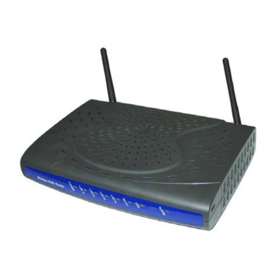
Page 9: Front Panel Led Indicators
Front Panel LED Indicators The front panel LEDs are shown in the picture below, followed by an explanation in the table below. Color Mode Function Power Green The router is powered up The router is powered down. Green Ethernet connection is established. Blink Data transmitting or receiving 1x~4x... -
Page 10: Chapter 2 Installation
Chapter 2 Installation Preparing for Hardware Installation The following equipment may be necessary to install the router: AC power adapter A suitable power adapter is shipped with the router. It is used to provide the necessary power for the router’s operation. LAN connection cable To connect to a hub or PC, use an RJ45 cable. -
Page 11: Hardware Installation
Hardware Installation Follow the instructions below to complete the hardware connections. Step 1 Connect the Line port to a telephone-line using the supplied RJ-11 cable; or if you wish to connect both the router and a telephone, connect the ADSL port to a micro filter or POTS splitter with a RJ11 connection cable. Step 2 To connect to a hub or PC, use a RJ45 cable. - Page 12 Step 3 (Optional) In order to manage your device through the console port you will need to use a straight-through cable with an RJ-45 connector to attach to the modem, and a female RS-232 connector to connect to the serial port on a PC. The PC must be equipped with a VT-100 emulation program, such as HyperTerminal 5 or Telix.
- Page 13 Step 5 Attach the power adapter to the wall outlet or other AC source. Step 6 After all connections have been made, turn the power-switch to the on position. After power on, the router performs a self-test. Wait for a few seconds until the test is finished, then the router will be ready to operate.
-
Page 14: Chapter 3 Login Via The Web Browser
Chapter 3 Login via the Web Browser This section describes how to manage the router via a Web browser from the remote end. You can use a web browser such as Microsoft Internet Explorer, or Netscape Navigator. It is best to set your display resolution to 1024 x 768. To change the resolution you can go to the Microsoft Windows control panel and click on the Display icon, and change the display settings. -
Page 15: Login Procedure
Login Procedure To log on to the system from the Web browser, follow the steps below: STEP 1: Start your Internet browser. STEP 2: Type the IP address for the router in the Web address field. For example, if the IP address is 192.168.1.1, type http://192.168.1.1 STEP 3:You will be prompted to enter your user name and password. -
Page 16: Chapter 4 Web Basic Configuration
Chapter 4 Web Basic Configuration From the Basic menu bar, you can verify the software version, change passwords, configure the WAN/LAN interfaces, set-up routing, save settings, reboot the device, and retrieve the factory default settings. Version Information To verify the software version of your router, from the Basic Menu bar, click on Version Information. -
Page 17: Adsl Link Status
ADSL Link Status To view the ADSL link status, click Link Status from the tool bar. The page includes the following information: ADSL Line Status Shows the current status of the ADSL line ADSL Mode Shows the ADSL standard that is currently configured. The ANSI, G.DMT, G.LITE, MULTI. -
Page 18: Wan Setup
WAN Setup Click WAN Setup from the tool bar and configure the WAN interface for these services: RFC1483 Bridged, RFC1483 Routed, PPPoE, PPPoA, and MER. The following are the common settings to set up these services. VPI and VCI LLC Encapsulation: With LLC encapsulation, a link control header is added to the Ethernet packet that identifies the protocol type (Ethernet). -
Page 19: Rfc 1483 Routed
DELETE AN ENTRY To delete an entry, Select it from the Current ATM PVC List, at the bottom of the WAN Setup page, and click the Delete button. 4.4.2 RFC 1483 Routed ADD AN ENTRY To set up the RFC 1483 Routed, configure the common settings on the top of the page, click RFC 1483 Routed and configure the specific settings (WAN IP address and WAN subnet mask). -
Page 20: Pppoe
4.4.3 PPPoE PPPoE provides service providers similar billing and access control as present in dial- up services. In addition, with direct support to Ethernet it provides a low cost solution to supporting multiple hosts at the customer premises. PPPoE provides session authentication using either Password Authentication Protocol (PAP) or Challenge Handshake Authentication Protocol (CHAP). - Page 21 ADD AN ENTRY To set up PPPoE, click PPPoE, configure the common fields on the top of the page, as well as the following fields. At the bottom of the screen, click the Add button to add the entry. In addition, If the PPPoE mode is set to auto, clicking the MANUAL MODE Enable button will effectively disable auto mode, and require the user to reconnect a terminated PPPoE session by clicking the MANUAL MODE Trigger button.
-
Page 22: Pppoa
4.4.4 PPPoA ADD AN ENTRY To set up PPPoA, click PPPoA, configure the common fields and the following fields. Click the Add button to add the entry. User name and Password: used for remote customers to login upon dialup. PPPoA is manually activated by entering startup commands from the page: Advanced>Configure PPPoA. -
Page 23: Mer
4.4.5 MER MAC Encapsulation Routing (MER) enables the ATU-R to route IP addresses on the RFC1483 bridged link. NAPT function is supported to allow multiple private IP addresses on the LAN to share a public IP address. To set up the MER service, configure the common fields, and then enter the IP Address and Subnet Mask under the MER section of the screen. -
Page 24: Lan Ip Address
LAN IP Address Click LAN Setup from the menu bar to configure the LAN IP address. Type the IP address and subnet mask. Click Apply to submit the settings. When the new IP address is applied, the Web configuration will be interrupted. Use the new IP address to login. -
Page 25: Wlan Configuration
WLAN Configuration Parameters that specifically deal with the wireless functions of your router can be accessed from WLAN Setup on the Basic menu bar. The menu is subdivided into three menus: WLAN Basic, WLAN Advanced, and WLAN WEP. Each of these menus will be covered below. -
Page 26: Wlan Basic Parameters
4.6.1 WLAN Basic Parameters To access the WLAN Basic parameters click on the WLAN Basic tab on the WLAN Settings screen. The WLAN Basic Parameters menu includes the parameters listed below. After changing any parameters, click on the Apply button to update the parameters, or click on the Restore button to retain the original settings. -
Page 27: Wlan Advanced Functions
4.6.2 WLAN Advanced Functions To access the WLAN Advanced parameters click on the WLAN Advance tab on the WLAN Settings screen. The WLAN Advanced Parameters menu includes the parameters listed below. After changing any parameters, click on the Apply button to update the parameters, or click on the Restore button to retain the original settings. -
Page 29: Wlan Wep Parameters
4.6.3 WLAN WEP Parameters: To access the WLAN WEP parameters click on the WLAN WEP tab on the WLAN Settings screen. This screen is used to set-up WEP security. WEP security uses an encryption keyword on all transmitted and received data. The parameters are described below. -
Page 30: Mac Filter
4.6.4 Mac Filter This screen allows access to be restricted/enabled based on a MAC address. Enter the following parameters and then click the Add button. MAC address: Enter the MAC address of the access point. Auth Type: enter Open System to allow unrestricted access to the access point, or Share Key to require confirmation with the parameters of the WEP security keys (Click the WEP tab to verify these settings). -
Page 31: Routing
Routing Click Routing Setup from the menu bar to configure the routing functions. Routing functions includes RIP and static routing. You can display the RIP information by clicking the RIP information button. -
Page 32: Enable Rip
4.7.1 Enable RIP To enable the RIP, complete the following steps: STEP 1: Click Routing Setup from the menu bar STEP 2: Select On in the Rip Status field. STEP 3: Select a RIP Version (Version 1 or Version 2) from the Version field. STEP 4: Click Apply to submit the settings. -
Page 33: Static Route Configuration
4.7.2 Static route configuration The Routes Configuration field allows you to add, modify, and delete a static route. Type the Destination Network ID, subnet mask, and next hop IP and click a button below to perform the requested function. - Page 34 Add: To add a static route complete the following steps: STEP 1: Click Routing Setup from the menu bar. STEP 2: Enter parameters for Destination Network ID, Subnet Mask, Next Hop IP, and Next Interface (note you must select between entering a Next Hop IP or Next interface).
-
Page 35: Save
Save To save the settings to Flash, click Save & Reboot from the menu bar. In the main pane, click Save. -
Page 36: Reboot
Reboot To reboot the router, click Save & Reboot from the menu bar. In the main pane, click on Reboot. -
Page 37: Retrieve Default Settings
4.10 Retrieve default settings To retrieve the default settings, click Erase & Reboot from the menu bar. In the main pane, click Erase. -
Page 38: Chapter 5 Web Advanced Configuration
Chapter 5 WEB Advanced Configuration ADSL Mode The ADSL modes are: ANSI, G.DMT, G.LITE, MULTI. MULTI mode enables the device to auto-adjust its mode to match the remote CO DLSAM. You can specify an ADSL mode on this page, and click the Apply button to submit the settings. VLAN To configure the VLAN function, click VLAN from the Advanced menu bar. -
Page 39: Dhcp
DHCP The Dynamic Host Configuration Protocol (DHCP) provides a centralized approach to allocating IP addresses. It allows IP addresses to be dynamically assigned on an as needed basis, from a pool of addresses. The DHCP function of the device is disabled by factory default. -
Page 40: Add A Dhcp Entry
5.3.3 Add a DHCP Entry To add an entry, click the Add button, and fill out the following parameters. Click Apply to submit the settings. Interface: eth0 only. This displays the interface that will provide the DHCP function. Starting IP Address: The first IP address of the address pool in the DHCP server. -
Page 41: Dhcp Relay
DHCP Relay The DHCP packet format is based on a BootP packet. As a result, DHCP uses the BootP relay agent to forward DHCP packets. This scheme provides interoperability between existing BootP clients and DHCP servers. The BootP relay agent uses the same criteria and methods for forwarding both DHCP and BootP packets. -
Page 42: Disable The Bootp/Dhcp Relay
5.4.2 Disable the BOOTP/DHCP Relay To disable the BOOTP/DHCP Relay complete the following steps: STEP 1: Access the BOOTP/DHCP Relay screen by clicking on DHCP on the Advanced Menu, and then click the BOOTP/DHCP Relay tab. STEP 2: In the DHCP Relay field, select Disable, and enter the IP Address you want to receive BOOT REQUEST or DHCP packets from clients. -
Page 43: Snmp
SNMP SNMP is a software entity that responds to information and action request messages sent by a network management station. The messages exchanged enable you to access and manage objects in an active or inactive (stored) MIB on a particular router. -
Page 44: Modifying Snmp Parameters
5.5.1 Modifying SNMP Parameters To modify the SNMP parameters, click the Modify button at the bottom of the screen. Click Apply to submit the settings. To configure the SNMP agent, click the Configure SNMP Agent button. After filling out the fields, click Apply to submit the settings. -
Page 45: Modifying Traps
5.5.2 Modifying Traps Click the Traps tab to configure the traps. After filling out the parameters, click Submit to apply the settings. -
Page 46: Modifying Communities
5.5.3 Modifying Communities Click the Communities tab to display the community entry. After filling out the parameters, click Submit to apply the settings. There is no community set up by factory default. To add or modify an entry, click the Configure Community button. -
Page 47: Firewall
Firewall The ADSL router provides packet filtering and stateful packet inspection, it has denial of service protection against attacks such as ICMP Flood, Ping of Death, IP spoofing, Port Scans, Land Attack, Tear Drop Attack, IP Source Route and WinNuke Attack. To access the firewall functions, select Firewall from the advanced menu. -
Page 48: View Firewall Actions
5.6.2 View Firewall Actions Click View Actions to display the list of currently configured firewall actions. The parameters are as follows: Action ID: Item number Interface: The interface the filtering rule is created on. Firewall Action: The action taken when packets are received that correspond to a filtering rule. - Page 49 Firewall Parameters Existing Action ID: If an action has already been established, check the box next to Existing Action ID and enter its Action ID. New Action: If a new action is required check the box next to New Action and then enter: Interface Name –the interface the action applies to, FW Action: Enter Allow, to enable packets to pass through the router, Deny to drop corresponding packets, Reject to reject packet with a response, e.g., sending a TCP reset, or...
-
Page 50: Nat
The NAT function can be accessed by clicking the NAT tab on the Advanced menu. From this screen you can add or delete a Static Wan Address, static NAT mapping or Port Range Mapping. 5.7.1 Static NAT Mapping Any Static NAT mapping entries that are set up will be listed, click on the Add button add a new entry or select an entry and click on the Delete button. -
Page 51: Static Port Mapping
5.7.2 Static Port Mapping Any Static WAN address that are set up will be listed, click on the Add button add a new entry or select an entry and click on the Delete button. Add an Entry To add an entry click on the Add button, and then enter the following information, and then click on the Apply button: Public IP Address: Enter the you wish to set the Public port range Public Port From: Enter the starting port for the Public port-range... -
Page 52: Configure
Configure From this page, you can configure LAN and WAN interfaces, VCC, PPPoE, PPPoA, DNS & Default Gateway, and NAT. -
Page 53: Configure Interface
5.8.1 Configure Interface To configure an interface, select it by clicking in the round-box on the left in the screen. Then click on the Configure Interface button at the bottom of the screen. Note the following: Interfaces: Interface mer0 usage is reserved; its status is always Down. Interface lo0 is the loopback interface. -
Page 54: Dns & Default Gateway
The following is a screen shot for the ATM interface. 5.8.2 DNS & Default Gateway To configure the DNS and default gateway, complete the following steps: STEP 1: Click on Configure in the menu bar. STEP 2: Click on DNS and default gateway at the bottom of the configuration page. -
Page 55: Nat
5.8.3 NAT The screen below is accessed by clicking the NAT button on the Configuration screen. To enable NAT check the Enable NAT box and the select the interface that you wish to enable NAT on. 1. Form the configuration menu click on the NAT button at the bottom-right side of the screen. -
Page 56: Vcc
This screen lists all current VCC entries in the middle of the screen. From this screen you can also: List IPoA, Delete Encapsulation, Add a VCC, Delete a VCC, and Show VCC quality. 5.9.1 List IPoA To list IP over ATM information click on the IPoA button at the bottom-left of the screen. -
Page 57: Delete Encapsulation
The IPoA entry is set up from Advanced>Configure>VCC, Click the Add button on the List of VCC screen. 5.9.2 Delete Encapsulation To delete encapsulation first select a VCC entry and then click the Delete Encap button. -
Page 58: Add A Vcc
5.9.3 Add a VCC To add a VCC entry, complete the following steps: STEP 1: Click on the Add VCC button, the VCC screen will appear. STEP 2: Enter values for the parameters (explained below). STEP 3: Click the Apply button at the bottom of the page. vpi: Virtual Path Identifier (VPI) that identifies this ATM connection. -
Page 60: Delete A Vcc
5.9.4 Delete a VCC To delete a VCC entry, select the entry from the list of VCCs and then click on the delete button, at the bottom-right of the page. 5.9.5 Show VCC quality To view information regarding the VCC quality, click on the Show VCC Quality button, at the bottom-right of the page. -
Page 61: Pppoa
5.10 PPPoA This section will describe how to start, stop, delete, and set a default PPPoA entry. The PPPoA page can be accessed by clicking on Configure in the Advanced menu bar. To start, stop, delete, or set as default a PPPoA entry first select the entry from the List of PPPoA entries, and then click the corresponding button at the bottom of the page. -
Page 62: Add An Igmp Entry
5.11.1 Add an IGMP entry To add an IGMP proxy, complete the following steps: STEP 1: Select IGMP Proxy, from the menu bar. STEP 2: Click Add at the bottom of the screen. STEP 3: Select Proxy interface, router interface, or both, by checking the box next to the interface and then use the pull-down menu to the left to select the eth, atm, or ppp Interface. -
Page 63: Bridging
5.12 Bridging 5.12.1 Bridge The Bridge window displays the configured Bridging PVC entries of the interfaces. There are four buttons at the bottom of the main-pane: Group Info, Add PVC, Flush, and Disable. GroupInfo: This configures the LAN packets that will travel through the LAN interface to the selected WAN interfaces. -
Page 64: Spanning Tree
AddPVC: You can add a PVC to the ATM interface. From the Bridging screen, select an ATM interface Vpi, Vci and Encapsulation type and then click Apply. Flush: Selecting this command from the Bridging screen, will flush all PVC entries. Disable: Selecting this command from the Bridging screen, will disable the PVCs but retain the parameters, so that they can be enabled at a later point. -
Page 65: View Stp Parameters
5.12.3 View STP Parameters To view the STP parameters, click the STP parameters tab, located at the bottom of the Spanning Tree screen. -
Page 66: To Configure Stp Parameters
5.12.4 To configure STP parameters STEP 1: click the Spanning Tree tab, located at the top of the Bridging screen. STEP 2: Click the Configure Port button. STEP 3: Configure the parameters. STEP 4: Click the Apply button. 5.12.5 Enable/Disable STP If you wish to Enable/Disable a STP entry, select the entry and then click the Enable or Disable Button, which is located at the bottom-right of the Spanning Tree screen. -
Page 67: Filtering
5.13 Filtering Filtering is a type of firewall that is useful to increase network security or to limit unwanted traffic. Filters for this device are based on MAC addresses. The page opens with a list of the currently configured filter entries. From this page, you can also view Filter Parameters, add a filter, delete a filter, modify a filter, or flush filter parameters. -
Page 68: Add A Filter Entry
5.13.2 Add a filter entry To add a filtering entry, complete the following steps: STEP 1: Click the Add button at the bottom of the Filters page. STEP 2: Enter the MAC address STEP 3: Set the Frame to forward to forward packets which match the MAC address, or Drop, to drop matching packets. -
Page 69: Chapter 6 Web Performance Monitoring
Chapter 6 Web Performance monitoring ADSL Link Status To view the ADSL link status, click Link Status on the tool bar. ADSL Line Status Shows the current status of the ADSL line ADSL Mode Shows the ADSL standard that is currently configured. The ANSI, G.DMT, G.LITE, MULTI. -
Page 70: System Statistics
System Statistics To view the system statistics, click on the System Statistics button located near the bottom of the menu-bar. Statistics are recorded regarding Interfaces, TCP-IP, and DHCP-Lease. 6.2.1 Interface Statistics To display the interface statistics, click the Interface tab, located at the top-left of the System Statistics screen. -
Page 71: Tcp-Ip
6.2.2 TCP-IP To view TCP-IP statistics click on the TCP-IP tab at the top of the System Statistics page. The TCP-IP page displays the IP statistics, UDP statistics, TCP statistics, and ICMP statistics. 6.2.3 DHCP-Lease To view TCP-IP statistics click on the DHCP-Lease tab at the top of the System Statistics page. -
Page 72: Atm Statistics
ATM statistics Click on ATM Statistics on the menu-bar to display the ATM Statistics. The ATM Statistics page monitors information for AAL5 and Encapsulation. 6.3.1 AAL5 The AAL5 page shows the AAl5 statistics. 6.3.2 Encapsulation Click on the SNDCP tab to display encapsulation statistics. This page displays the VCs that are running. -
Page 73: Chapter 7 Web Diagnostics
Chapter 7 Web Diagnostics To access the Diagnostics screen, click the Diagnostics button, which is located on the menu bar. The Diagnostics screen has two test functions: OAM Loopback and Ping test. OAM Loopback STEP 1: lick the Diagnostics button, on the menu bar. STEP 2: Click the Loopback tab on the Diagnostics screen. -
Page 74: Ping
Ping A Ping test is used to verify the status of a network connection after the RIP or static route function is enabled. Ping sends a request message to the host and waits for a return message. This diagnostic function can verify if the remote host is reachable. Ping can also measure the round-trip time to the remote host. -
Page 75: Chapter 8 Firmware Upgrade
Chapter 8 Firmware Upgrade Follow the steps below to upgrade the firmware version of the wireless router via the FTP: STEP 1: Connect the Router to a PC using the LAN cable. Set the PC to the same subnet as the router (192.168.1.1). STEP 2: Restore the default parameters to the wireless router by holding down the device’s Reset button until the Power LED turns red (about 5 seconds). - Page 76 STEP 8: After you see the message Type set to I, type: ha STEP 9: After you see the message Hash mark printing, type: put <filename > app.1 (if the file name has extension, also type the extension. Example: put eagle.ct app.1 STEP 10: After a moment, the file should begin transferring, after you see the message Transfer complete, the upgrade process is complete.
-
Page 77: Chapter 9 Access By Telnet
Chapter 9 Access by Telnet This chapter will introduce the command line interface using Telnet. The chapter is divided into two parts. The first part explains how to set the PC and router to the same network segment, the second part explains how to start a Telnet session. Setting a Common IP Address To log on to the device using Telnet, your workstation and the router should both be on the same network segment. -
Page 78: Telnet Access
Telnet Access To access Telnet to manage your router complete the following steps: The default IP address is 192.168.1.1. Use the default IP address to log on to the router if it was not changed. STEP 1 Make sure that the router and your Telnet-PC are on the same network segment. -
Page 79: Chapter 10 Console Management
Chapter 10 Console Management This section of the manual deals with console management of the router. 10.1 Hardware connection In order to manage your device through the console port you will need to use a straight-through cable with an RJ-45 connector to attach to the modem, and a female RS-232 connector to connect to the serial port on a PC. - Page 80 Step 3 After the session parameters are set up, as shown in Step 2, the screen will display as below. (For some versions you may need to press the ESC or Enter Key.
-
Page 81: Console Wlan Guide
10.3 Console WLAN Guide Parameters that specifically deal with the wireless functions of your router can be accessed from the WLAN Parameters menu, located at BASIC/WLAN CONFIGURATION. The menu is subdivided into three menus: Basic Settings, Advanced Functions and WEP Functions. Each of these menus will be covered below. -
Page 82: Wlan Basic Parameters
10.3.1 WLAN Basic Parameters To configure WLAN basic Parameters go to BASIC/WLAN CONFIGURATIION/BASIC PARAMETERS, enter values for the required parameters and then press the Y key when prompted by the following message Do You Wish To Submit These Values [Y/N]. The WLAN Basic Parameters menu includes the parameters listed below: IP Address Enter the IP address for the WLAN interface Subnet Mask... -
Page 83: Wlan Advanced Functions
10.3.2 WLAN Advanced Functions To configure WLAN Advance Parameters go to BASIC/WLAN CONFIGURATIION/ADVANCE PARAMETERS, enter values for the required parameters and then press the Y key when prompted by the following message Do You Wish To Submit These Values [Y/N]. The WLAN Advanced Functions menu includes the parameters listed below: Beacon Interval Default =100. -
Page 84: Wlan Wep Parameters
10.3.3 WLAN WEP Parameters: WEP security uses an encryption keyword on all transmitted and received data. To configure WLAN basic Parameters go to BASIC/WLAN CONFIGURATIION/WEP PARAMETERS, enter values for the required parameters and then press the Y key when prompted by the following message Do You Wish To Submit These Values [Y/N]. -
Page 85: Appendix A: Specifications
Appendix A: Specifications Wireless Card Standard IEEE802.11b Encryption 64, 128-bit Wired Equivalent Privacy (WEP) Data Encryption Channels 11 Channels (US, Canada) 13 Channels (Europe) 14 Channels (Japan) Data Rate 11Mbps / 5.5Mbps / 2Mbps /1Mbps Auto-Fallback RF Frequency 2412 MHz – 2484 MHz (Japan) 2412 MHz –... - Page 86 Routing Functions Routing Static route, RIP, and RIPv2 NAT/PAT Security Authentication protocols PAP, CHAP, MS-CHAP VPN features PPTP/L2TP pass through Power Supply 100, or 220 VAC Dimensions 205 * 145 * 48 mm Specifications are subject to change without notice...
-
Page 87: Appendix B - Pin Assignments
Appendix B - Pin Assignments Pin Definitions of the LAN port Pin number Definition Pin number Definition Transmit data+ 5 Transmit data- 6 Receive data- Receive data+ 7 Note: NC means No connection Pin Assignments of RJ11 Port Definition Definition RING Note: NC means No connection Console cable...