
Related Manuals for Vaisala Humicap HMT310


Summary of Contents for Vaisala Humicap HMT310
- Page 1 USER'S GUIDE Vaisala HUMICAP® Humidity and Temperature Transmitter HMT310 M210619EN-C...
- Page 2 The contents are subject to change without prior notice. Please observe that this manual does not create any legally binding obligations for Vaisala towards the customer or end user. All legally binding commitments and agreements are included exclusively in the applicable supply contract or Conditions of...
-
Page 3: Table Of Contents
HMT314 for Pressurized Spaces ........22 HMT315 for High Temperatures ........24 HMT317 for Demanding Processes....... 24 HMT318 for Pressurized Pipelines/Oils ......25 Tightening the Clasp Nut ..........27 Connections................28 Cable Wiring................ 28 Screw Terminal Connector..........29 VAISALA ________________________________________________________________________ 1... - Page 4 USER'S GUIDE____________________________________________________________________ CHAPTER 4 OPERATION....................31 Power ON/OFF ................31 Entering Serial Communication Parameters .......31 List of Commands ..............33 Measurement Output..............35 R Start Continuous Outputting ..........35 S Stop Continuous Outputting..........36 INTV Set Continuous Output Interval for RUN-Mode..36 SEND Output Reading Once..........36 SMODE Set Serial Interface Mode........37 SERI Serial Line Settings ............37 ADDR Set Transmitter Address for Use in POLL-Mode ..38 OPEN Temporarily Open Transmitter from POLL-Mode to...
- Page 5 Filter Change............... 60 Sensor Change ..............61 Parts List for Consumables ..........61 Technical Support ..............62 Return Instructions ..............62 Vaisala Service Centers............63 CHAPTER 7 CALIBRATION AND ADJUSTMENT............64 Calibration and Adjustment Commands......64 LI Revert Factory Calibration ..........64 FCRH Relative Humidity Calibration after Sensor Change 65 CTEXT Set Calibration Information Text......
- Page 6 USER'S GUIDE____________________________________________________________________ Duct Installation Kits (for HMT313/317/315)......80 Pressure-Tight Swagelok Installation Kits (for HMT317) ...81 RH Probe Installation............81 Examples of Vapor-Tight Installations with Cable Gland...82 RH Probe Installations (for HMT313/317) ......82 Ball Valve Installation kit for HMP318 ........83 4 ___________________________________________________________________ M210619EN-C...
- Page 7 Swagelok Installation Kit for RH Probe ........81 Figure 21 Cable Installation with Cable Gland AGRO......82 Figure 22 Probe Installation with Cable Gland (not available from Vaisala)83 Figure 23 Installing the HMP318 Probe Through a Ball Valve Assembly 84 VAISALA ________________________________________________________________________ 5...
- Page 8 USER'S GUIDE____________________________________________________________________ List of Tables Table 1 Manual Revisions ...............8 Table 2 HMT310 Output Quantities............16 Table 3 HMT318 Probe Dimensions .............26 Table 4 Entering Serial Parameters in Windows® 2000 and Windows NT® ..................32 Table 5 Quantity Abbreviations for FORM Command......40 Table 6 Modifiers ...................40 Table 7...
-
Page 9: Chapter 1 General Information
- Chapter 6, Maintenance, provides information that is needed in basic maintenance of HMT310, and lists contact information for technical support and Vaisala Service Centers. - Chapter 7, Calibration and Adjustment, describes the relative humidity and temperature adjustment procedures. -
Page 10: Version Information
USER'S GUIDE____________________________________________________________________ - Chapter 8, Technical Data, provides the technical data of the product. - Appendix A, Probe Installation Kits and Installation Examples. Version Information Table 1 Manual Revisions Manual Code Description M210619EN-A June 2004 - First release M210619EN-B September 2005 M210619EN-C September 2007 - Added HUMICAP®... -
Page 11: Feedback
ESD Protection Electrostatic Discharge (ESD) can cause immediate or latent damage to electronic circuits. Vaisala products are adequately protected against ESD for their intended use. However, it is possible to damage the product by delivering electrostatic discharges when touching, removing, or inserting any objects inside the equipment housing. -
Page 12: Recycling
USER'S GUIDE____________________________________________________________________ Recycling Recycle all applicable material. Dispose of batteries and the unit according to statutory regulations. Do not dispose of with regular household refuse. Regulatory Compliances The Humidity and Temperature Transmitter HMT310 complies with the following performance and environmental test standards: Electromagnetic Compatibility EN 61326-1:1997 + Am1:1998 + Am 2:2001 Electrical equipment for measurement, control and laboratory use - EMC requirements;... -
Page 13: Emissions
EN/IEC 61000-4-4 criteria B transients) Surge EN/IEC 61000-4-5 criteria B Conducted immunity EN/IEC 61000-4-6 criteria A Trademarks ® VAISALA HUMICAP is a registered trademark of Vaisala. ® ® ® ® Microsoft , Windows , Windows NT, and Windows 2000 are registered trademarks of Microsoft Corporation in the United States and/or other countries. -
Page 14: Warranty
Products should Vaisala so require, be sent to the works supplied hereunder, which obligations of Vaisala or to such other place as Vaisala may liabilities are hereby expressly cancelled and indicate in writing, freight and insurance waived. Vaisala's liability... -
Page 15: Chapter 2 Product Overview
This chapter introduces the features, advantages, and the product nomenclature. Introduction to HMT310 ® The Vaisala HUMICAP Humidity and Temperature Transmitter HMT310 is a small size humidity and temperature transmitter that powers up with 12 .. 35 VDC. Output alternatives are analog outputs 0/4 ... -
Page 16: Components
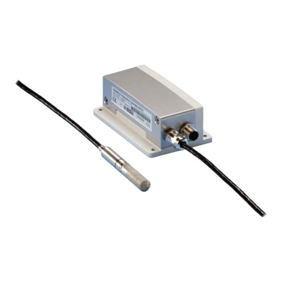
USER'S GUIDE____________________________________________________________________ Components 0507-032 Figure 1 HMT310 Components The following numbers refer to Figure 1 above: Transmitter unit Mounting plate (smaller mounting plate also available) Connector for signal output and power supply. Available with female connector with 5 m cable or screw terminal connector. Probe 14 _______________________________________________________________ M210619EN-C... -
Page 17: Probe Options
Chapter 2 __________________________________________________________ Product Overview Probe Options 0507-033 Figure 2 HMT310 Probes The following numbers refer to Figure 2 above: HMT311 for wall mounting HMT313 for general use HMT314 for pressurized spaces up to 100 bar HMT315 for high temperatures up to 180°C (242 mm long probe, vapor-tight) HMT317 for demanding processes (warmed and vapor-tight probe) -
Page 18: Output Quantities
USER'S GUIDE____________________________________________________________________ Output Quantities Table 2 HMT310 Output Quantities Quantity Metric Unit Nonmetric Unit RH Relative humidity T Temperature °C °F °C °F Dewpoint/Frostpoint TD Dewpoint °C °F A Absolute humidity gr/ft X Mixing ratio g/kg gr/lb °C °F TW Wet bulb temperature PPM Humid air volume/ dry air volume... -
Page 19: Chapter 3 Installation
Chapter 3 _______________________________________________________________ Installation CHAPTER 3 INSTALLATION This chapter provides you with information that is intended to help you install the HMT310. Selecting Location Finding a suitable site for the Humidity and Temperature Transmitter HMT310 is important for getting representative ambient measurements. -
Page 20: Figure 3 Mounting With Mounting Plates
USER'S GUIDE____________________________________________________________________ The transmitter module can be unfastened for calibration by releasing the two Allen screws on the left side. 0507-034 Figure 3 Mounting with Mounting Plates The following letters and numbers refer to Figure 3 above: Mounting with larger mounting plate Mounting with smaller mounting plate Two Allen screws for fastening or removing the transmitter module (Allen key provided) -
Page 21: Mounting The Probes
Chapter 3 _______________________________________________________________ Installation 0507-035 Figure 4 Mounting Plate Dimensions The following letters refer to Figure 4 above: Larger mounting plate dimensions Smaller mounting plate dimensions Mounting the Probes Do not unsolder and then again resolder the probe cable from the mother board during installation;... -
Page 22: General Instructions For Probes With Cable
USER'S GUIDE____________________________________________________________________ 0507-036 Figure 5 Measurement Error at 100 %RH when Difference Between Ambient and Sensor Temperature is 1 °C General Instructions for Probes with Cable It is recommended that the probes with a cable are mounted with the probe horizontal; this way, any water condensing on the tube cannot flow onto the sensor. -
Page 23: Figure 7 Vertical Mounting Of Probe
Chapter 3 _______________________________________________________________ Installation When there is no alternative but to install the probe in the process vertically, the point of entry must be carefully insulated. The cable must also be allowed to hang loosely as this prevents any condensed water from running onto the probe along the cable. -
Page 24: Hmt313 For General Use
The HMT313 is a small size (d = 12mm) general-purpose probe suitable for ducts and channels with the installation kit available from Vaisala. The HMT313 provides for two measuring range options. The first probe version is equipped with a flexible cable and can be used when measuring in environments up to 80 ºC. -
Page 25: Figure 8 Hmt314 Installation
Chapter 3 _______________________________________________________________ Installation 0507-040 Figure 8 HMT314 Installation The following numbers refer to Figure 8 above: Tightening cone Fitting screw Sealing washer Probe; Ø 12 mm M22×1.5 or NPT 1/2" Tighten the nut a further 30° (1/12 turn) or if you have a torque spanner tighten it with a torque of 80 ±... -
Page 26: Hmt315 For High Temperatures
USER'S GUIDE____________________________________________________________________ In pressurized processes it is essential to tighten the supporting nuts CAUTION and screws very carefully to prevent loosening of the probe by the action of pressure. When HMT314 is installed in a process with pressure differing from NOTE normal atmospheric pressure, please enter the pressure value of the process (in hPa or mbar) into the transmitter memory via the serial... -
Page 27: Hmt318 For Pressurized Pipelines/Oils
Chapter 3 _______________________________________________________________ Installation HMT318 for Pressurized Pipelines/Oils Due to the sliding fit the HMT338 is easy to install into and remove from the pressurized process. The probe is especially suitable for the measurements in pipelines. See section Ball Valve Installation kit for HMP318 on page 83. -
Page 28: Figure 11 Sealing Of Fitting Body Into Process
USER'S GUIDE____________________________________________________________________ The following two fitting body options are available: - Fitting Body ISO1/2 solid structure - Fitting Body NPT1/2 solid structure Table 3 HMT318 Probe Dimensions Probe Type Probe Dimension Adjustment Range Standard 178 mm 120 mm Optional 400 mm 340 mm 0507-025 Figure 11... -
Page 29: Tightening The Clasp Nut
Chapter 3 _______________________________________________________________ Installation Tightening the Clasp Nut Adjust the probe to a suitable depth according to the type of installation. Tighten the clasp nut first manually. Mark the fitting screw and the clasp nut. Tighten the nut a further 50 - 60º (ca. 1/6 turn) with a wrench. If you have suitable torque spanner, tighten the nut to max 45 ±... -
Page 30: Connections
USER'S GUIDE____________________________________________________________________ In pressurized processed it is essential to tighten the supporting nuts CAUTION and screws very carefully to prevent loosening of the probe by the action of pressure. When HMT318 is installed in a process with pressure differing from NOTE normal atmospheric pressure, please enter the pressure value of the process (in hPa or mbar) into the transmitter memory via the serial... -
Page 31: Screw Terminal Connector
Chapter 3 _______________________________________________________________ Installation The following numbers and codes refer to Figure 13: Color Function 1 White (WHT) RS-232 TX 2 Brown (BRN) RS-232 GND 3 Green (GRN) CH2+ 4 Yellow (YEL) CH1+ 5 Grey (GREY) Supply-/CH1-/CH2 - 6 Pink (PINK) Supply+ 7 Blue (BLU) RS-232 RX... - Page 32 USER'S GUIDE____________________________________________________________________ This page intentionally left blank. 30 _______________________________________________________________ M210619EN-C...
-
Page 33: Chapter 4 Operation
Chapter 4 ________________________________________________________________ Operation CHAPTER 4 OPERATION This chapter contains information that is needed to operate Humidity Transmitter HMT310. Power ON/OFF Switch on the 24 VDC power supply and the transmitter wakes up. Entering Serial Communication Parameters The transmitter communicates via an RS-232 serial interface. The transmitter can be polled or set on RUN-mode with specific commands. -
Page 34: Table 4 Entering Serial Parameters In Windows® 2000 And Windows Nt
USER'S GUIDE____________________________________________________________________ Table 4 Entering Serial Parameters in Windows® 2000 and Windows NT® WINDOWS 2000 WINDOWS NT MENU WHAT TO DO MENU WHAT TO DO Start Start move the cursor to: move the cursor to: Programs Programs move the cursor to: move the cursor to: Accessories Accessories... -
Page 35: List Of Commands
Chapter 4 ________________________________________________________________ Operation 0507-046 ® Figure 15 HyperTerminal Settings in Windows 2000 Environment List of Commands The text in BOLD letters in the [brackets] indicates the default setting. Issue the commands by typing them on your computer keyboard. <cr> stands for pressing Enter (on your computer keyboard). - Page 36 USER'S GUIDE____________________________________________________________________ Output formatting FORM Serial output format TIME Set time DATE Set date FTIME [ON/OFF] Add time to SEND and R outputs FDATE [ON/OFF] Add date to SEND and R outputs UNIT Select metric or nonmetric output units FST [ON/OFF] Output state of optional probe heating and chemical purge (with SEND and R commands)
-
Page 37: Measurement Output
Chapter 4 ________________________________________________________________ Operation Calibration and adjustment (these are presented in Chapter 7, section Calibration and Adjustment Commands on page 64) Relative humidity calibration Temperature calibration Revert factory calibration FCRH Relative humidity calibration after sensor change CTEXT Set calibration information text CDATE Set calibration date ACAL... -
Page 38: S Stop Continuous Outputting
USER'S GUIDE____________________________________________________________________ S Stop Continuous Outputting Syntax: S<cr> Stops the continuous output. Also the Esc key (on your computer keyboard) can be used to stop outputting. INTV Set Continuous Output Interval for RUN-Mode Syntax: INTV xxx yyy<cr> where Output interval (0 ... 255) Unit (s, min or h) Example: >intv 1<cr>... -
Page 39: Smode Set Serial Interface Mode
Chapter 4 ________________________________________________________________ Operation SMODE Set Serial Interface Mode Syntax: SMODE x<cr> where STOP/RUN/POLL STOP-mode: Transmitter in standby for serial commands RUN-mode: Transmitter outputs data continuously POLL-mode: Transmitter only responds to addressed command Example: >smode run<cr> Output mode : RUN >smode stop<cr>... -
Page 40: Addr Set Transmitter Address For Use In Poll-Mode
USER'S GUIDE____________________________________________________________________ ADDR Set Transmitter Address for Use in POLL-Mode Syntax: ADDR aa<cr> where Address (0 ... 99) Example: >addr<cr> Address >addr 1<cr> Address OPEN Temporarily Open Transmitter from POLL-Mode to Receive Serial Commands Syntax: OPEN nn<cr> where Address of the transmitter (0 ... 99) The OPEN command sets the bus temporarily in STOP-mode so that the SMODE command can be issued. -
Page 41: Close Set Transmitter In Poll-Mode
Chapter 4 ________________________________________________________________ Operation CLOSE Set Transmitter in POLL- Mode Syntax: CLOSE<cr> In STOP-mode: command OPEN has no effect, CLOSE sets the transmitter temporarily in POLL-mode. In POLL-mode: command OPEN sets the transmitter temporarily in STOP-mode, command CLOSE returns the instrument to POLL- mode. -
Page 42: Table 5 Quantity Abbreviations For Form Command
USER'S GUIDE____________________________________________________________________ Format string consists of quantities and modifiers: use the quantity abbreviations and modifiers presented in Table 5 below and in Table 6 below when selecting the output quantities. Table 5 Quantity Abbreviations for FORM Command Abbreviation Quantity Relative humidity Temperature Dewpoint/Frostpoint Dewpoint... -
Page 43: Time, Date Setting Time And Date
Chapter 4 ________________________________________________________________ Operation TIME, DATE Setting Time and Date Syntax: TIME<cr> Syntax: DATE<cr> Sets the time and date to the transmitter. Example: >time<cr> Current time is 04:12:39 Enter new time (hh:mm:ss) ? 12:24:00<cr> >date<cr> Current date is 2000-01-01 Enter new date (yyyy-mm-dd) ? 2004-06-30<cr> >... -
Page 44: Unit Select Metric Or Nonmetric Output Units
USER'S GUIDE____________________________________________________________________ UNIT Select Metric or Nonmetric Output Units Syntax: UNIT x<cr> where M or N M = metric units N = nonmetric units Table 7 Output Quantities and their Metric and Nonmetric Units Quantity Metric Unit Nonmetric Unit RH Relative Humidity T Temperature °C °F... -
Page 45: Fst Output State Of Chemical Purge Or Sensor Heating (With Send And R Commands)
Chapter 4 ________________________________________________________________ Operation FST Output State of Chemical Purge or Sensor Heating (with SEND and R Commands) Syntax: FST x<cr> where ON/OFF (default = OFF) Example: >fst on<cr> Form. status : ON >send 0 RH= 40.1 %RH T= 24.0 'C Td= 9.7 'C Tdf= 9.7 'C 8.7 g/m3... -
Page 46: Other Commands
POLL state. Example (factory default settings): >?<cr> HMT310 / 1.07 PRB serial nr : A0000000 Calibration : 2004-05-07 Cal. info : Vaisala/HEL Output units : metric Pressure : 1013.25 hPa RS232 settings Address Output interval: 0 S Baud P D S... -
Page 47: Find All Devices In Poll-Mode Send Their Addresses
Chapter 4 ________________________________________________________________ Operation FIND All Devices in POLL-Mode Send Their Addresses Syntax: FIND<cr> HELP List Commands Syntax: HELP<cr> PRES Set Ambient Pressure for Calculations Syntax: PRES aaaa.a<cr> Syntax: XPRES aaaa.a<cr> where aaaa.a Absolute pressure (hPa) Command XPRES should be used if the value is changed frequently. Its value is not retained at reset, and when set to 0, value set with PRES is used. -
Page 48: Table 8 Pressure Conversion Chart
Conversions from mmHg and inHg are defined at 0 °C and for NOTE mmH2O and inH2O at 4 °C. Pressure compensation is intended to be used in normal air only. NOTE When measuring in other gases, please contact Vaisala for further information. 46 _______________________________________________________________ M210619EN-C... -
Page 49: Filt Set Result Filtering
Chapter 4 ________________________________________________________________ Operation FILT Set Result Filtering Syntax: FILT xx<cr> Enable or disable the filtering or select the extended filter to reduce noise of the measurement. where ON, OFF or EXT ON = Short filter of about 15 s (results the average value of the last 15 s measurement data) OFF = No filtering (default) EXT = Extended filter of about 1 min (results the... -
Page 50: Setting, Scaling And Testing Analog Outputs
USER'S GUIDE____________________________________________________________________ Setting, Scaling and Testing Analog Outputs AMODE Set Analog Outputs (0/4 ... 20 mA) Syntax: AMODE ch1 ch2<cr> where ch1 and ch2 I0 = 0 ... 20 mA I1 = 4 ... 20 mA Example: >amode i1 i1<cr> Ch1 output mode: 4...20mA Ch2 output mode: 4...20mA >... -
Page 51: Table 9 Output Quantities And Their Metric And Nonmetric Units
Chapter 4 ________________________________________________________________ Operation Table 9 Output Quantities and their Metric and Nonmetric Units Quantity Metric Unit Nonmetric Unit RH Relative Humidity °C °F T Temperature °C °F Dewpoint/frostpoint °C °F TD Dewpoint A Absolute humidity gr/ft X Mixing ratio g/kg gr/lb °C... -
Page 52: Ascl Scale Analog Outputs
USER'S GUIDE____________________________________________________________________ ASCL Scale Analog Outputs Syntax: ASCL<cr> Example: >ascl<cr> Ch1 Td -40.00 'C Ch1 Td 100.00 'C Ch2 x 0.00 g/kg Ch2 x 500.00 g/kg ITEST Test Analog Outputs Syntax: ITEST aa.aaa bb.bbb<cr> The operation of the analog outputs are tested by forcing the outputs to given values. -
Page 53: Aqtest Test Analog Outputs For Desired Readings
Chapter 4 ________________________________________________________________ Operation AQTEST Test Analog Outputs for Desired Readings Syntax: AQTEST x yyy.yyy<cr> Use command AQTEST to test current values. Current output is forced to correspond the chosen values. where Output quantity of analog channel (use abbreviations, see FORM Serial Output Format on page 39) yyy.yyy Value... -
Page 54: Chemical Purge (Optional)
USER'S GUIDE____________________________________________________________________ The error output value is shown only when there are minor electrical NOTE faults such as a humidity sensor open circuit. When there is a severe device malfunction, like analog output electronics failure or microprocessor ROM/RAM failure, the error output value is not necessarily shown. -
Page 55: Automatic/Manual Chemical Purge
Chapter 4 ________________________________________________________________ Operation Calibration values Chemical purge Measured values after chemical exposure Humidity 0507-056 Figure 16 Decrease of Sensor Gain Due to Interfering Chemical and Effect of Chemical Purge Process Automatic/Manual Chemical Purge When HMT310 leaves the factory the automatic chemical purge (if selected) takes place repeatedly with the time intervals set in the factory. -
Page 56: Pur Set Chemical Purge Interval
USER'S GUIDE____________________________________________________________________ Syntax: PUR x<cr> where ON/OFF Example: >pur off Chemical Purge : OFF >pur on Chemical Purge : ON > PUR Set Chemical Purge Interval If the sensor is exposed to chemicals it is recommended to have the chemical purge done at least once in 720 min (= 12 hours). In applications where the chemical exposure is not likely, the interval may be longer. -
Page 57: Chemical Purge Activated Manually
Chapter 4 ________________________________________________________________ Operation Syntax: PURR x<cr> where ON/OFF (default = OFF) When you enable this function, wait about 8 min after powerup NOTE before taking measurements. The powerup chemical purge locks the output values for the first operation minutes. Chemical Purge Activated Manually Chemical purge needs to be performed always before calibration (see Calibration and Adjustment on page 64) or whenever there is reason... -
Page 58: Sensor Heating
USER'S GUIDE____________________________________________________________________ Sensor Heating General This function is optionally available only in transmitters with ® ® HUMICAP HUMICAP sensor. It should be used only 180C or 180RC with the warmed probe. The sensor heating is recommended for the high humidity environments where even a small temperature differences can cause water to condense on the sensor. -
Page 59: Setting Heating Parameters
Chapter 4 ________________________________________________________________ Operation Syntax: XHEAT x<cr> where ON/OFF (default = OFF) >xheat on Extra heat : ON >xheat off Extra heat : OFF > Setting Heating Parameters Whenever the RH value seen by the sensor exceeds the predefined RH limit the humidity sensor is warmed up to the predefined temperature. -
Page 60: Measuring At Overpressure
USER'S GUIDE____________________________________________________________________ CHAPTER 5 MEASURING AT OVERPRESSURE This chapter contains important information concerning the use of HMT310 in overpressure conditions. HMT314 and HMT318 are designed for humidity measurement at overpressure. The maximum measurement pressures depend on the probe as follows: - HMT314: 0 ... - Page 61 Chapter 5 __________________________________________________ Measuring at Overpressure This page intentionally left blank. VAISALA____________________________________________________________________ 59...
-
Page 62: Chapter 6 Maintenance
You can carry out calibration and adjustment by yourself, or you can send the transmitter to Vaisala Service Centers for recalibration. Replacing Consumables Filter Change Remove the filter from the probe. -
Page 63: Sensor Change
Chapter 6 ______________________________________________________________ Maintenance New filters can be ordered from Vaisala, see Parts List for Consumables below. Sensor Change You can change Vaisala HUMICAP®180, HUMICAP®180L, and HUMICAP®180R sensors. Remove the filter from the probe. Remove the damaged sensor and insert a new one. Handle the new sensor by the plastic socket. -
Page 64: Technical Support
Include the information specified in step 2 in the box with the faulty product. Also include a detailed return address. Ship the box to the address specified by your Vaisala contact. 62 _______________________________________________________________ M210619EN-C... -
Page 65: Vaisala Service Centers
Chapter 6 ______________________________________________________________ Maintenance Vaisala Service Centers Vaisala Service Centers perform calibrations and adjustments as well as repair and spare part services. See contact information below. Vaisala Service Centers also offer accredited calibrations, maintenance contracts, and a calibration reminder program. Do not hesitate to contact them to get further information. -
Page 66: Calibration And Adjustment
USER'S GUIDE____________________________________________________________________ CHAPTER 7 CALIBRATION AND ADJUSTMENT This chapter describes the relative humidity and temperature adjustment procedures. After adjustment, the original calibration certificate shipped with the product is not valid anymore. Calibration and Adjustment Commands LI Revert Factory Calibration Syntax: LI<cr> This command reverts only the CRH calibration (see calibration instructions, starting on page 67). -
Page 67: Fcrh Relative Humidity Calibration After Sensor Change
Chapter 7 ___________________________________________________Calibration and Adjustment Example: >li<cr> RH offset : -0.6000000 ? 0 RH gain 1.00000000 ? 1 offset : 0.00000000 ? 0 gain 0.40000000 ? 1 > FCRH Relative Humidity Calibration after Sensor Change Syntax: FCRH<cr> The transmitter asks and measures relative humidity and calculates the calibration coefficients. -
Page 68: Cdate Set Calibration Date
USER'S GUIDE____________________________________________________________________ Example: >ctext<cr> Cal. info : Vaisala/HEL ? HMK15<cr> > CDATE Set Calibration Date Syntax: CDATE yyyy mm dd<cr> Remove the transmitter unit from the mounting plate (see Mounting the Transmitter/ Removing the Transmitter Unit on page 17) and press the adjustment button once (see Figure 17 on page 67). -
Page 69: Relative Humidity Calibration And Adjustment (In Two Points)
Chapter 7 ___________________________________________________Calibration and Adjustment Relative Humidity Calibration and Adjustment (in Two Points) Use two reference humidities over the measurement range. The references need to have a difference of at least 50 %RH. Before calibration HMT310 needs to be set to adjustment mode by pressing the adjustment button once, see Figure 17 below. -
Page 70: Low End Adjustment
USER'S GUIDE____________________________________________________________________ Low End Adjustment Remove the transmitter unit from the mounting plate (see Mounting the Transmitter/ Removing the Transmitter Unit on page 17), and press the adjustment button once (see Figure 17 on page 67). Remove the filter from the probe (see instructions on page 60) and insert the probe into the measurement hole of the dry end reference chamber (for example, LiCl: 11 % RH in the humidity calibrator HMK15, use adapter fitting 13.5 mm for HMT314,... -
Page 71: Temperature Calibration And Adjustment (In One Point)
Chapter 7 ___________________________________________________Calibration and Adjustment When stabilized, type the high-end reference value after the question mark and press Enter. >crh 11.25 Ref1 ? c 11.24 Ref1 ? c 11.24 Ref1 ? 11.3 Press any key when ready ... 75.45 Ref2 ? c 75.57 Ref2 ? c 75.55... - Page 72 USER'S GUIDE____________________________________________________________________ When the reading is stabilized, type the reference temperature after the question mark and press Enter three times. >ct 16.06 Ref1 ? c 16.06 Ref1 ? c 16.06 Ref1 ? c 16.06 Ref1 ? c 16.06 Ref1 ? c 16.06 Ref1 ? 16.0 Press any key when ready ...
- Page 73 Chapter 7 ___________________________________________________Calibration and Adjustment This page intentionally left blank. VAISALA____________________________________________________________________ 71...
-
Page 74: Chapter 8 Technical Data
Relative Humidity Specifications Property Description / Value Measuring range 0 ... 100 %RH Accuracy (including nonlinearity, hysteresis and repeatability) with Vaisala HUMICAP®180 for typical applications Vaisala HUMICAP®180R for typical applications Vaisala HUMICAP®180C for applications with chemical purge and/or warmed probe Vaisala HUMICAP®180RC... -
Page 75: Figure 18 Accuracy Over Temperature Range
Chapter 8 ____________________________________________________________ Technical Data Response time (90 %) for 17 s with grid filter HUMICAP®180R and 50 s with grid + steel netting filter HUMICAP®180RC at 20 °C in 60 s with sintered filter 0.1 m/s air flow Table 12 Temperature Specifications (+ Operating Pressure Ranges) Property... -
Page 76: Table 13 Electronics Specifications
USER'S GUIDE____________________________________________________________________ Table 13 Electronics Specifications Property Description / Value Cable feed through alternatives 8-pole connector with 5 m cable Female 8-pin connector screw joint for cable diameter 4 ... 8 mm Operating voltage 12 ..35 VDC, the maximum operating voltage for device with sensor heating is 24 VDC Power consumption... -
Page 77: Options And Accessories
Stainless Steel Filter HM47453SP Stainless Steel Filter with Membrane 214848SP Sensors Vaisala HUMICAP®180 (general 19279HM purpose) Vaisala HUMICAP®180R (general HUMICAP180R purpose) Vaisala HUMICAP®180L2 (for high 210314HM chemical concentrations) PT100 sensor 10429SP Probe mounting accessories Fitting Body M22x1.5 17223 Fitting Body NPT1/2 17225... -
Page 78: Dimensions In Mm (Inches)
USER'S GUIDE____________________________________________________________________ Dimensions in mm (inches) Transmitter Enclosure and Mounting Plates 0507-049 The following numbers refer to the figure above. Mounting plate alternatives: Wall Plate/Cover, DRW212957 (bigger plate) Wall Plate/Cover (No Flange), DRW214786 (smaller plate) 76 _______________________________________________________________ M210619EN-C... -
Page 79: Probes
Chapter 8 ____________________________________________________________ Technical Data Probes HMT311 12 (0.47) 0507-050 HMT313 0508-008 VAISALA____________________________________________________________________ 77... -
Page 80: Hmt314
USER'S GUIDE____________________________________________________________________ HMT314 0507-052 HMT315 41 (1.61) (1.06) 2 (0.08) 192 (7.56) 242 (9.53) 0507-053 Flange for HMT315 available as an option 78 _______________________________________________________________ M210619EN-C... -
Page 81: Hmt317
Chapter 8 ____________________________________________________________ Technical Data HMT317 0508-009 HMT318 0507-055 VAISALA____________________________________________________________________ 79... -
Page 82: Probe Installation Kits And Installation Examples
Duct installation kit includes a flange, a sealing ring, a supporting bar and probe attaching part for the probe and screws for attaching the flange to the duct wall. Vaisala order codes: 210697 (for HMT313) and 210696 (for HMT315, no supporting bar). -
Page 83: Pressure-Tight Swagelok Installation Kits (For Hmt317)
Appendix A _________________________________ Probe Installation Kits and Installation Examples When the temperature difference between the duct and the air outside NOTE the duct is significant, the supporting bar must be installed as deep in the duct as possible. This helps to prevent errors caused by heat conduction in the bar and cable. -
Page 84: Examples Of Vapor-Tight Installations With Cable Gland
Cable Installation with Cable Gland AGRO The following numbers refer to Figure 21 above: Nut (to be tightened to the body) Seal Body and O-ring Vaisala order code for the cable gland: HMP247CG (see Table 15 Options and Accessories on page 75). 82 _______________________________________________________________ M210619EN-C... -
Page 85: Ball Valve Installation Kit For Hmp318
In pressurized conditions, use a locking ring (for example, 11x 1 DIN471) The installation option in Figure 22 above is not available from Vaisala and is presented here only as an example of how to achieve a vapor-tight installation with HMT313/317 probes. Ball Valve Installation kit for HMP318... -
Page 86: Figure 23 Installing The Hmp318 Probe Through A Ball Valve Assembly
USER'S GUIDE____________________________________________________________________ 0507-043 Figure 23 Installing the HMP318 Probe Through a Ball Valve Assembly The following numbers refer to Figure 23 above: Manual press tool Handle of the ball valve Probe Process chamber or pipeline Groove on the probe indicates the upper adjustment limit Filter Ball of the ball valve Clasp nut... - Page 87 Appendix A _________________________________ Probe Installation Kits and Installation Examples Follow the steps below to install the HMP318 probe through a ball valve assembly. After the installation, the probe should be sitting in the process chamber or pipeline as shown in Figure 23 on page 84. Shut down the process if the process pressure is more than 10 bars.
- Page 88 USER'S GUIDE____________________________________________________________________ 86 _______________________________________________________________ M210619EN-C...
- Page 89 *M210619EN*...