Advertisement
Quick Links
INTRODUCTION
DMT242 is a dewpoint transmitter for wide range of OEM applications. DMT242 measures dewpoint
with excellent long term stability which is maintained automatically with the patented auto-calibration
procedure. The Vaisala DRYCAP
dew in case condenced water exists in the process during system malfunction. The product mechanics
have been designed for harsh environments requiring protection against dust, dirt and splashed water.
The disconnection and reconnection of the transmitter is easy with the connector where the output signal
and supply voltage wires are connected. The unit also has a serial line for rescaling the analog output.
PRESSURE SETTING PROCEDURE FOR PRESSURIZED PROCESSES
For achieving the most accurate measurements
in pressurized processes, set the process
pressure to DMT242 according to Figure 1 by
using the pressure switches (see Figure 3, item
8). As shipped from factory, the pressure
switch setting is 1 bar, as in switch number 4 in
the ON position.
MOUNTING
1. Insert the sealing washer (see Figure 1) on
the probe and set the probe through the
fitting of the process pipe. The probe has
G½" ISO 228/1 parallel thread.
2. Fasten the transmitter to the fitting of the
process pipe by tightening from the nut of
the probe (24 mm).
WIRING
1. Remove the cover.
2. Take out the connector.
3. Take out the screw terminal from the
connector by pushing it out, for example,
with the fixing screw.
4. Use a three-wire cable. Suitable 2 m or
10 m optional cable is available from
Vaisala (items: 221475 for 2 m cable and
221476 for 10 m cable). Connect the wires
to the connector terminals as follows:
Terminal nr 1 = V supply + (VAC line)
Terminal nr 2 = V supply - (VAC neutral)/signal -
Terminal nr 3 = Signal +
Leave the ground terminal free
Vaisala DRYCAP
U
'
G
SER
S
UIDE
®
polymer sensor technology used in DMT242 is also durable against
®
Dewpoint Transmitter DMT242
June 2008 | M010036EN-D
Switches
1
2 3 4
Figure 1 Pressure Setting Table
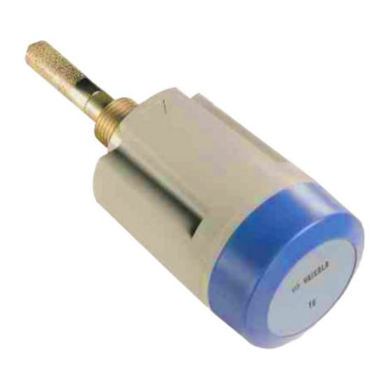
Figure 2 DMT242
-
Pressu re (absolu te)
(bar)
0 ... 2
2 ... 4
4 ... 6
6 ... 8
THE SWITCH MARKED WITH
8 ... 10
A BLACK SQUARE IS IN
10 ... 12
ON
THE
POSITION
12 ... 14
14 ... 16
16 ... 18
18 ... 20
1 = Cover
2 = Connector
3 = Flat gasket
4 = Counter connector
5 = Transmitter body
6 = Nut
7 = Sealing washer
8 = Probe
Wire colours in cables
221475 and 221476:
1 = brown
+
2 = blue
3 = black
Advertisement

Related Manuals for Vaisala Drycap DMT242


Summary of Contents for Vaisala Drycap DMT242
- Page 1 4. Use a three-wire cable. Suitable 2 m or 10 m optional cable is available from Vaisala (items: 221475 for 2 m cable and 221476 for 10 m cable). Connect the wires to the connector terminals as follows:...
- Page 2 By using a connection cable the readings of DMT242 and DM70 can be viewed simultaneously on the display of DM70. If there is need for adjustement contact Vaisala Instruments Service Centers or local Vaisala representative.
- Page 3 Connect the DMT242 to a serial bus via the RS-232 interface by using the following settings: Baud rate: 2400, Parity: none, Data bits: 8, Stop bits: 1. The serial cable (DMT242RS) can be ordered from Vaisala. Scaling of the dewpoint output Scale the dewpoint parameter by giving the command ascl xx yy<ENTER>...
-
Page 4: Dewpoint Temperature
® Vaisala DRYCAP Dewpoint Transmitter DMT242 UIDE June 2008 | M010036EN-D TECHNICAL SPECIFICATIONS Output Dewpoint Temperature Analog output 4 ... 20 mA Measurement range -80 ... +60 °C (-112 ... +140 °F) Resolution for analog output ±0.002 mA DMT242A -80 ... +20 °C (-112 ... +68 °F) Typical temperature dependence 0.0008 mA/ºC...