
Related Manuals for Vaisala Humicap MMT162


Summary of Contents for Vaisala Humicap MMT162
- Page 1 USER'S GUIDE ® Vaisala HUMICAP Moisture and Temperature Transmitter for Oil MMT162 M210934EN-B...
- Page 2 The contents are subject to change without prior notice. Please observe that this manual does not create any legally binding obligations for Vaisala towards the customer or end user. All legally binding commitments and agreements are included exclusively in the applicable supply contract or Conditions of...
-
Page 3: Table Of Contents
Trademarks ................8 License Agreement ..............8 Warranty..................8 CHAPTER 2 PRODUCT OVERVIEW.................. 9 Introduction to MMT162............9 Basic Features and Options..........10 Transmitter Structure............. 10 Typical Applications .............. 12 Method Used for Measuring Moisture in Oil......12 Lubrication Oil ..............12 Transformer Oil .............. - Page 4 Closing the Connection to a Transmitter in POLL Mode..39 Display Command List ............40 Reset Transmitter ..............41 Restore Factory Settings.............41 ppm Conversion ..............41 MMT162 ppm Conversion for Transformer Oils....41 Conversion Model with Average Coefficients......42 Conversion Model with Oil-specific Coefficients ....42 Setting Oil Coefficients Using Serial Line......43 OIL..................43 Determination of Oil-Specific Coefficients ......43...
- Page 5 Spare Parts and Accessories..........61 Dimensions in mm (inches) ..........62 List of Figures Figure 1 Moisture and Temperature Transmitter for Oil MMT162..11 Figure 2 The Water Solubility of Transformer Oils versus Temperature 14 Figure 3 Removing the Transportation Protection Cap ......15 Figure 4 Installing the Transmitter ............
- Page 6 User's Guide ______________________________________________________________________ This page intentionally left blank. 4 ___________________________________________________________________ M210934EN-B...
-
Page 7: Chapter 1 General Information
This manual provides information for installing, operating, and ® maintaining Vaisala HUMICAP Moisture and Temperature Transmitter for Oil MMT162. Contents of This Manual This manual consists of the following chapters: - Chapter 1, General Information, provides general notes for the manual and the product. -
Page 8: Version Information
Manual Name ® M210935EN-A Vaisala HUMICAP Moisture and Temperature Transmitter for Oil MMT162 Quick Reference Guide General Safety Considerations Throughout the manual, important safety considerations are highlighted as follows: WARNING Warning alerts you to a serious hazard. If you do not read and follow instructions very carefully at this point, there is a risk of injury or even death. -
Page 9: Product Related Safety Precautions
Product Related Safety Precautions ® The Vaisala HUMICAP Moisture and Temperature Transmitter for Oil MMT162 delivered to you has been tested for safety and approved as shipped from the factory. Note the following precautions: Ground the product, and verify outdoor installation grounding WARNING periodically to minimize shock hazard. -
Page 10: Trademarks
Microsoft Corporation in the United States and/or other countries. License Agreement All rights to any software are held by Vaisala or third parties. The customer is allowed to use the software only to the extent that is provided by the applicable supply contract or Software License Agreement. -
Page 11: Chapter 2 Product Overview
ISO and NPT 1/2. The MMT162 probe is supplied with a three or five meter connection cable. The MMT162 also provides for accurate temperature measurement. It is an easy-to-install on-line probe which can be calibrated against, for example, traceable salt solutions. -
Page 12: Basic Features And Options
(>> 1 m/s) Transmitter Structure The structure of the MMT162 is shown in Figure 1 on page 11. The transmitter body does not have user serviceable parts inside, and is not designed to be opened. Opening the transmitter will void the warranty. -
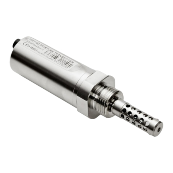
Page 13: Figure 1 Moisture And Temperature Transmitter For Oil Mmt162
4-pin M8 connector I: analog output channels and operating power 4-pin M8 connector II (shown with protective cap): digital output (RS-485) and operating power 30 mm nut ® HUMICAP sensor protected with stainless steel grid filter Connection thread: ISO G1/2" or NPT 1/2" VAISALA _______________________________________________________________________ 11... -
Page 14: Typical Applications
The most important advantages of this system are the fact that water activity is immune to the aging of oil and to additives, and that the MMT162 transmitter can be used for continuous on-line measurements. In addition, the MMT162 can be calibrated against salt solutions and no reference oils are needed. -
Page 15: Transformer Oil
Saturation level is thus a true indicator of moisture present. The MMT162 method provides for a reliable detection of the aging of oil and possible leakages. -
Page 16: Figure 2 The Water Solubility Of Transformer Oils Versus Temperature
User's Guide ______________________________________________________________________ WATER SOLUBILITY IN MINERAL TRANSFORMER OIL 10000 1000 average water solubility range of variation due to oil type range of variation due to oil type Temperature (°C) 0510-029 Figure 2 The Water Solubility of Transformer Oils versus Temperature The margins show the range of variation of water solubility found in mineral oils. -
Page 17: Chapter 3 Installation
Use your hands to turn the probe until it feels tight. Do not use force at this point, and check that the sealing ring (if used) remains centered. VAISALA _______________________________________________________________________ 15... -
Page 18: Figure 4 Installing The Transmitter
User's Guide ______________________________________________________________________ 0805-006 Figure 4 Installing the Transmitter Use a 30 mm wrench to tighten the connection to 25 Nm, as shown in Figure 4 above. If you do not have a 30 mm wrench, use a 1 3/16” wrench or an adjustable wrench instead. CAUTION Only tighten the probe from the 30 mm nut. -
Page 19: Wiring
Chapter 3 _______________________________________________________________ Installation Wiring Wire Colour Brown Analog output 1 RS-485 B White Blue Analog output 2 / LED RS-485 A Black 0707-035 Figure 6 Connectors I and II 0707-036 Figure 7 Connector Pinout VAISALA _______________________________________________________________________ 17... -
Page 20: Connection Cables
User's Guide ______________________________________________________________________ Connection Cables The following connection cable options are available for MMT162: - Unshielded cable with M8 female straight snap-on connector - Shielded cables with M8 female straight threaded connector - Shielded cables with M8 female 90° angle threaded connector... -
Page 21: Figure 10 Cable With 90° Angle Threaded Connector
Chapter 3 _______________________________________________________________ Installation 0809-004 Figure 10 Cable with 90° Angle Threaded Connector 0809-003 Figure 11 LED Cable VAISALA _______________________________________________________________________ 19... -
Page 22: Power Supply Requirements
For the cable order codes, see section Spare Parts and Accessories on page 61. Power Supply Requirements The MMT162 transmitters are designed to operate with a supply voltage of 14 … 24 VDC. The power supply should maintain the voltage for all load conditions. -
Page 23: Chapter 4 Operation
OPERATION This chapter contains information that is needed to operate this product. Getting Started MMT162 is ready to be used once it has been connected to a power source. Analog Output Operation Modes The MMT162 has two analog output channels. These channels can... -
Page 24: Normal Operation Mode And Malfunction Alarm
LED to blink at 0.5 Hz frequency. LED alarm indicator is integrated to a LED cable (Vaisala item MP300LEDCBL) that can be ordered and used instead of a regular connection cable. -
Page 25: Serial Communication
Chapter 4 ________________________________________________________________ Operation Serial Communication Connecting to Serial Interface The MMT162 can be connected to a PC using the RS-485 line, for example using the USB serial connection cable (Vaisala item 219690). The cable also provides operation power to the transmitter from the USB port. -
Page 26: Installing The Driver For The Usb Cable
Link detects the USB connection automatically. There is no reason to uninstall the driver for normal use. However, if you wish to remove the driver files and all Vaisala USB cable devices, you can do so by uninstalling the entry for Vaisala USB Instrument Driver from the Add or Remove Programs (Programs and Features in Windows Vista) in the Windows Control Panel. -
Page 27: Terminal Program Settings
Terminal Program Settings The default settings of the MMT162 serial interface are presented in Table 4 on page 23. If the settings of your MMT162 have been changed and you do not know what they are, refer to section Restore Factory Settings on page 41. -
Page 28: Figure 13 Putty Terminal Application
User's Guide ______________________________________________________________________ 0807-004 Figure 13 PuTTY Terminal Application 26 __________________________________________________________________ M210934EN-B... -
Page 29: List Of Serial Commands
SERI [baud p d s] User Port settings (Default: 4800 E 7 1) baud: 300 ... 115200 SMODE Set the serial interface mode [STOP/RUN/POLL] UNIT [M/N] Select the metric or non-metric output units VERS Display the software version information VAISALA _______________________________________________________________________ 27... -
Page 30: Device Information And Status
The ? command outputs a listing of device information. If you wish to display the listing for all devices on the current serial line, issue the command ??. ?<cr> ??<cr> Example: >? MMT162 0.92 Serial number : G0000002 Batch number : D0720012 Module number : ???????? -
Page 31: Configuring Serial Line Operation
4800 O 7 1 changing all parameters >SERI 600 N 8 1 600 N 8 1 > You can use the SERI command to change/view the user port settings even if you are currently connected to the service port. VAISALA _______________________________________________________________________ 29... -
Page 32: Set Serial Line Response Time
User's Guide ______________________________________________________________________ Set Serial Line Response Time With the SDELAY command, you can set delay (response time) for user port RS-485, or view currently set delay value. Value corresponds to tens of milliseconds (for example 5 = 0.050 s minimum answer delay). The value can be set between 0...255. -
Page 33: Table 6 Modifiers
Chapter 4 ________________________________________________________________ Operation Formatter string consists of quantities and modifiers. The MMT162 measures the following quantities: water activity (aw) temperature (T) (metric unit: ºC, non metric unit:ºF) - ppm for transformer oil only (H When selecting the quantity, use the abbreviations of the quantities. The modifiers are presented in Table 6 on page 31 below. -
Page 34: Select Unit
User's Guide ______________________________________________________________________ Select Unit Use the UNIT command to select metric or non-metric output units. UNIT [x] where M or N where Metric units Non-metric units Set Serial Interface Mode Use the SMODE command to set the default serial interface mode. SMODE [xxxx] where xxxx... -
Page 35: Set Analog Output Mode (Ma/V)
= Quantity of channel 1 yyy = Quantity of channel 2 Always enter all the quantities for all outputs. The MMT162 measures the following quantities: water activity (aw) temperature (T) (metric unit: ºC, non metric unit: ºF) ppm for transformer oil only (H... -
Page 36: Calibrate Analog Output
User's Guide ______________________________________________________________________ Calibrate Analog Output Use the ACAL command to adjust analog output channels. To adjust channel 1, use parameter 1 and to adjust channel 2, use parameter 2 as in the example below. After entering the ACAL command, use a calibrated current/voltage meter to measure the output, and enter the values. -
Page 37: Set Alarm Limits For Analog Outputs / Led Indication
Level Hi 0.80 Set Voltage for LED Alarm With the LED command, you can set a different voltage level for each channel. Example: led ? Ch 1 Led Voltage 2.80 V Ch 2 Led Voltage 2.80 V VAISALA _______________________________________________________________________ 35... -
Page 38: Extend Analog Output Range
User's Guide ______________________________________________________________________ Extend Analog Output Range Use the AOVER command to allow the analog output channels to exceed their specified range by 10 %. The scaling of the quantity remains as before; the extra range is used for additional measurement range in the wet end. -
Page 39: Set Output Interval
= Transmitter address (0 ... 99). Must be specified if the transmitter is in POLL mode, and a line has not been opened using the OPEN command. Example: >SEND T= 25.2 'C aw= 0.299 H2O= 19 ppm RS= 29.9 % > VAISALA _______________________________________________________________________ 37... -
Page 40: Troubleshooting Commands
Channel 1 output value (V or mA) Channel 2 output value (V or mA) The output shows the test values of the analog channels, and diagnostic information that may be useful to Vaisala Service if there is a problem with the analog outputs. Example: >atest 1 15... -
Page 41: Other Commands
(0 ... 99) Example: open 0 MMT162 0 line opened for operator commands Closing the Connection to a Transmitter in POLL Mode The CLOSE command closes the connection to the transmitter. CLOSE<cr> Example: >close line closed > VAISALA _______________________________________________________________________ 39... -
Page 42: Display Command List
User's Guide ______________________________________________________________________ Display Command List Use the HELP command to list the available commands. HELP<cr> Example: help ACAL ADDR ADJD AERR ALARM AMODE AOVER ASEL ATEST CDATE CLOSE CTEXT ERRS FILT FORM FRESTORE HELP INTV OILI OPEN PCOMP PRES RESET SDELAY SEND... -
Page 43: Reset Transmitter
The ppm output shows the average mass concentration of water in oil. The moisture and temperature transmitter MMT162 has an option for ppm-output provided that this has been notified when placing the order for the transmitter. Vaisala has this conversion readily available for mineral transformer oils. -
Page 44: Conversion Model With Average Coefficients
Coefficients For additional accuracy, oil-specific conversion model can be used both for mineral and silicon based oils. An oil sample has to be sent to Vaisala for modelling. As a result, the specific coefficients (A and B, see formula 1) for the transformer oil are determined by Vaisala. For additional information, please contact Vaisala. -
Page 45: Setting Oil Coefficients Using Serial Line
If you have defined the coefficients or separately received from Vaisala the oil-specific coefficients A and B, related to your own oil type, the coefficients can be set to the software of MMT162 by using serial line. Use the serial line command OIL to display oil-specific parameters for ppm conversion. - Page 46 Define the water content of the oil sample with the titration. Use the oil moisture level that is close to real conditions in the process. Measure the water activity of this sample with MMT162 at two temperatures that differ at least 20 °C. Follow the measurement stabilization illustrated by the graph.
- Page 47 213/0.188 = 1132.979 A = (LOG(1132.98)-LOG(445.607))/(1/(57.6+273.16)- 1/(24.1+273.16)) = -1189.4581 B= LOG(445.607)-(-1189.4581)/(24.1 + 273.16) = 6.6503583 Assumptions: The isoterm of water activity versus water concentration is linear and the solubility curve has the form of the given equation. VAISALA _______________________________________________________________________ 45...
- Page 48 User's Guide ______________________________________________________________________ This page intentionally left blank. 46 __________________________________________________________________ M210934EN-B...
-
Page 49: Chapter 5 Maintenance
Cleaning Clean the transmitter enclosure with a soft. lint-free cloth moistened with mild detergent. Clean the sensor before storing the MMT162 probe and before calibration. For cleaning the the probe you need instrument air and heptane (C ) liquid. If heptane is not available, you can also use diesel oil or petrol. -
Page 50: Changing The Probe Filter
New filters can be ordered from Vaisala, see section Spare Parts and Accessories on page 61. Changing the Sensor If you need to change the sensor on your MMT162, send it to Vaisala where the sensor will be changed for you. Error States... -
Page 51: Technical Support
Read the section Warranty on page 8. Contact a Vaisala Service Center or a local Vaisala representative. The latest contact information and instructions are available from www.vaisala.com. Addresses of the Service Centers are provided in section Vaisala Service Centers on page 50. -
Page 52: Vaisala Service Centers
Include the information specified in step 2 in the box with the faulty product. Also include a detailed return address. Ship the box to the address specified by your Vaisala contact. Vaisala Service Centers Vaisala Service Centers perform calibrations and adjustments as well as repair and spare part services. -
Page 53: Calibration And Adjustment
You can calibrate the MMT162 yourself or send it to Vaisala for calibration. Calibration and adjustment is usually carried out through serial line. -
Page 54: Mm70 In Checking And Adjusting
User's Guide ______________________________________________________________________ MM70 in Checking and Adjusting MMT162 can be checked and adjusted by using the MM70. In the field you can check and adjust the probe's reading against the calibrated reference probe of the MM70. To check the MMT162 transmitter with MM70: Connect the MMT162 to the MM70 indicator with the appropriate connection cable (Vaisala item 219980). -
Page 55: Using Mi70
Take the probe out of the reference conditions and replace the filter. Using MI70 To adjust the relative humidity: Connect MI70 to MMT162. Turn MI70 on. On the MI70, go to Menu → Functions → Adjustments Figure 14 Main Menu... - Page 56 User's Guide ______________________________________________________________________ Follow the instructions given on the display. Select RH from the list and press Select. When adjusting relative humidity, you need to check the environment settings before making the adjustment. 54 __________________________________________________________________ M210934EN-B...
- Page 57 Chapter 6 ___________________________________________________Calibration and Adjustment In adjustment mode, enter the correct reference value and then exit by pressing Back . VAISALA _______________________________________________________________________ 55...
-
Page 58: One-Point Temperature Adjustment
User's Guide ______________________________________________________________________ One-Point Temperature Adjustment The MMT162 must be unpowered during stabilization which can take 30 minutes or more. Using Serial Line Remove the probe filter and insert the probe into the reference temperature. Enter the command CT and press ENTER . -
Page 59: Using Mi70
Chapter 6 ___________________________________________________Calibration and Adjustment Using MI70 To adjust temperature: Connect MI70 to MMT162 via connector II. Turn on MI70. On the MI70 display, go to Menu → Functions → Adjustments . Follow the instructions given on the MI70 display. -
Page 60: Analog Output Adjustment
- current output: 2 mA and 18 mA - voltage output: 10 % and 90 % of the range Connect MMT162 to a calibrated current/voltage meter in order to measure either current or voltage depending on the selected output type. -
Page 61: Chapter 7 Technical Data
-40 ... +80 °C (-40 ... +176 °F) Accuracy at +20 °C (+68 °F) ± 0.2 °C (± 32.36 °F) Typical temperature dependence of electronics ± 0.005 °C/°C (± 0.003 °F/°F) Sensor Pt 100 RTD 1/3 Class B IEC 751 VAISALA _______________________________________________________________________ 59... -
Page 62: Operating Environment
User's Guide ______________________________________________________________________ Operating Environment Operating temperature -40 ... +60 °C (40 ... +140°F) Pressure range metal version up to 200 bar plastic version up to 40 bar Complies with EMC standard EN61326-1:1997+ Am1:1998 + Am2:2001 Industrial environment Oil flow some flow recommended Inputs and Outputs Minimum operating voltage with current output... -
Page 63: Spare Parts And Accessories
2 m (9.8 ft) shielded cable, 90° angle connector 221739 5 m (16.4 ft) shielded cable, 90° angle connector 221740 Sampling cells (available only for ISO G1/2") Sampling cell DMT242SC Sampling cell with 1/4" male Swagelok DMT242SC2 connectors VAISALA _______________________________________________________________________ 61... -
Page 64: Dimensions In Mm (Inches)
User's Guide ______________________________________________________________________ Dimensions in mm (inches) 0804-084 Figure 16 Metal Housing Transmitter Dimensions 62 __________________________________________________________________ M210934EN-B... -
Page 65: Figure 17 Plastic Housing Transmitter Dimensions
Chapter 7 ____________________________________________________________ Technical data 0804-085 Figure 17 Plastic Housing Transmitter Dimensions VAISALA _______________________________________________________________________ 63... - Page 66 *M210934EN*...