Vaisala HMD60U Operating Manual
Humidity transmitter/humidity and temperature transmitter
Hide thumbs
Also See for HMD60U:
- Operating manual (4 pages) ,
- User manual (18 pages) ,
- Operating manual (21 pages)
Table of Contents
Advertisement
Quick Links
Download this manual
See also:
User Manual
HMD60U/Y-U166en-1.2
HUMIDITY TRANSMITTER HMD60U
HUMIDITY AND TEMPERATURE TRANSMITTER HMD60Y
MOUNTING
62 (2.44)
250 (9.84)
Ø 12
(0.47)
100 (3.94)
Mounting hole 82 (3.23)>>>
Figure 1 Dimensions of the HMD60U/Y
GROUNDING
flexible wires 0.5 mm²
(AWG 20), stranded wires
recommended
3
braid
brass
disks
25
rubber
ring
nut
D = Ø 7...10mm
cable
(If the cable diameter is less
than 7mm, use a shrinking
tube or an adhesive tape)
Figure 2 Signal cable grounding with
bushing 18941HM
1996-04-12
shielding tube
braid
brass disks
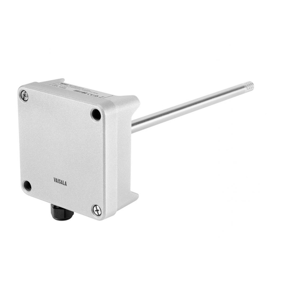
The
HMD60U/Y
temperature transmitters are two-wire
transmitters. They are duct mounted, and
the electronics can be disconnected
without dismantling the installation.
Mount the transmitter with two screws.
Place the drilling template on the duct
surface and drill the holes as indicated.
Remember to drill an additional hole for
calibration purposes. The calibration can
be conveniently performed on site with
the HMI41 indicator equipped with an
appropriate
probe
calibration cable.
Open the lid and mount the cable
bushing set 18941HM. Do the grounding
according to Figure 2. W
the signal cable to the transmitter housing,
fold the cable braid between the brass disk
in order to achieve the best EMC per-
formance. Do not leave the bare shield of
the connected wires so that it can
shortcircuit the electronics!
HMD60U/Y
Operating Manual
humidity
and
and
optional
hen connecting
1
Advertisement
Table of Contents

Related Manuals for Vaisala HMD60U


Summary of Contents for Vaisala HMD60U
- Page 1 HMI41 indicator equipped with an appropriate probe optional calibration cable. Mounting hole 82 (3.23)>>> Figure 1 Dimensions of the HMD60U/Y GROUNDING flexible wires 0.5 mm² (AWG 20), stranded wires recommended Open the lid and mount the cable bushing set 18941HM. Do the grounding according to Figure 2.
-
Page 2: Electrical Connections
HMD60U/Y Operating Manual HMD60U/Y-U166en-1.2 ELECTRICAL CONNECTIONS TEST RH GAIN TEST 3 4 5 RH OFFSET T OFFSET T GAIN Figure 3: Electrical connections Signal cables are connected to a removeable 5-pole screw connector. Make the connections according to Figure 3 above. RH test and T test connectors are used with the HMI41 indicator equipped with an appropriate probe and optional calibration cable. - Page 3 HMI41 indicator equipped with an attempt to clean the filter. appropriate probe optional calibration cable. adjustment needed, use the one-point calibration potentiometer. If you prefer to calibrate the HMD60U/Y transmitters against saturated salt solutions, use LiCl (11 %RH) and NaCl (75 %RH) solutions. 1996-04-12...
-
Page 4: Technical Data
GUARANTEE Output signal 4...20 mA Operating temperature range: electronics -5...+55 C Vaisala issues a guarantee for the material and sensor head -40...+80 C workmanship of this product under normal operating Storage temperature range -40...+80 C conditions for one year from the date of delivery. - Page 5 HMW60U/Y HMW60U/Y-U190en-1.2 Operating Manual HUMIDITY TRANSMITTER HMW60U HUMIDITY AND TEMPERATURE TRANSMITTER HMW60Y MOUNTING The HMW60U/Y humidity and tempera- 33 (1.30) 85 (3.35) ture transmitters are truly two-wire transmitters that can be mounted directly on the wall. First attach the base plate with the two screws provided.
- Page 6 0.1 C Temperature sensor Pt 1000 IEC 751 class B Vaisala issues a guarantee for the material and workmanship of this product under normal operating conditions for one year from the date of delivery. General Exceptional operating conditions, damage due to...
- Page 7 HMD70U/Y HMD70U/Y-U162en-1.4 Operating Manual HUMIDITY TRANSMITTER HMD70U HUMIDITY AND TEMPERATURE TRANSMITTER HMD70Y MOUNTING The HMD70U/Y duct mounted humidity 62 (2.44) 250 (9.84) 100 (3.94) and temperature transmitters are three- wire transmitters. Mount the transmitter with two screws. Place the drilling Ø...
-
Page 8: Electrical Connections And Installation Of The Current Module
HMD70U/Y Operating Manual HMD70U/Y-U162en-1.4 ELECTRICAL CONNECTIONS AND INSTALLATION OF THE CURRENT MODULE INSTALLATION OF THE CURRENT MODULE 18945HM OUTPUT SELECTIONS 1. Take off the jumpers 0...1V Connect the module; note the right direction! 0...5V Connect the power supply 0...10V TEST CONNECTOR 0...20mA current... - Page 9 HMD70U/Y HMD70U/Y-U162en-1.4 Operating Manual TO REMOVE THE SENSOR HEAD: 1. Open the lid 2. Disconnect the screw terminal 3. Open the screws (2 pcs) 4. Pull out carefully SCREW TERMINAL TO REINSTALL THE SENSOR HEAD SCREWS 1. Push in the sensor head 2.
- Page 10 20...35 V 17...24 V Factory setting 0...1V. Other outputs selectable by jumper connections. An output change causes an error Vaisala issues a guarantee for the material and which is less than 0.5 %RH without recalibration. workmanship of this product under normal operating conditions for one year from the date of delivery.
- Page 11 HMW70U/Y HMW70U/Y-U191en-1.2 Operating Manual HUMIDITY TRANSMITTER HMW70U HUMIDITY AND TEMPERATURE TRANSMITTER HMW70Y MOUNTING The HMW70U/Y humidity and tempera- ture transmitters can be mounted directly on the wall. First attach the base plate 33 (1.30) with the two screws provided. Thread 85 (3.35) wires through...
- Page 12 HMW70U/Y Operating Manual HMW70U/Y-U191en-1.2 CONNECTION TO AN AC SUPPLY HMW70U/Y transmitter Controller RH/T signal The HMW70U/Y transmitters can also be connected to an AC supply without an external rectifier. However, when more than one transmitter is connected to one RH/T signal AC transformer, a common loop is formed and there is an increased risk of a...
- Page 13 When an AC supply is used, an isolated source is recommended. 0...1 V 10...35 V 9...24 V Vaisala issues a guarantee for the material and 0...5 V 14...35 V 12...24 V workmanship of this product under normal operating 0...10 V 19...35 V...