
Related Manuals for Vaisala HMT100


Summary of Contents for Vaisala HMT100
- Page 1 Humidity and Temperature Transmitter HMT100 UIDE M210701EN-A June 2005...
- Page 2 The contents are subject to change without prior notice. Please observe that this manual does not create any legally binding obligations for Vaisala towards the customer or end user. All legally binding commitments and agreements are included exclusively in the applicable supply contract or...
-
Page 3: Table Of Contents
Trademarks ................7 License Agreement ..............7 Warranty..................8 CHAPTER 2 PRODUCT OVERVIEW.................. 9 Introduction to the HMT100 Humidity and Temperature Transmitter................9 Product Description............9 Fixed and Remote Probe Models ........10 Optional Display ............. 10 HMT100 Transmitter Components......... 11 CHAPTER 3 INSTALLATION.................... - Page 4 Plastic Wall Assembly Plate .............13 Figure 4 Plastic Wall Assembly Plate with Aluminium Installation Plate 14 Figure 5 HMT100 Installation with Rain Shield........15 Figure 6 Installation of the Humidity Probe with the Radiation Shield..16 Figure 7 Probe Installation with the Duct Installation Kit ......17 Figure 8 Assembly of the Humidity Probe with the Duct Installation Kit.18...
- Page 5 ________________________________________________________________________________ Figure 20 Dimensions HMT100 Fixed Probe Model ........ 45 Figure 21 Dimensions HMT100 Remote Probe Model......46 List of Tables Table 1 Manual Revisions ............... 5 Table 2 Related Manuals ................ 5 Table 3 Wiring Table ................20 Table 4 Common Problems During Adjustment and Their Remedies ..
- Page 6 User's Guide ______________________________________________________________________ This page intentionally left blank. 4 ________________________________________________________________ M210701EN-A...
-
Page 7: Chapter 1 General Information
CHAPTER 1 GENERAL INFORMATION This chapter provides general notes for the manual and the product. About This Manual This manual provides information for installing, operating, and maintaining the Humidity and Temperature Transmitter HMT100. Version Information Table 1 Manual Revisions Manual Code... -
Page 8: General Safety Considerations
Product Related Safety Precautions The Humidity and Temperature Transmitter HMT100 delivered to you has been tested for safety and approved as shipped from the factory. Note the following precautions: Do not modify the unit. Improper modification can damage the CAUTION product or lead to malfunction. -
Page 9: Esd Protection
Do not dispose of with regular household refuse. Trademarks HUMICAP® is a registered trademark of Vaisala. License Agreement All rights to any software are held by Vaisala or third parties. The customer is allowed to use the software only to the extent that is VAISALA_____________________________________________________________________ 7... -
Page 10: Warranty
Software License Agreement. Warranty For certain products Vaisala normally gives a limited one-year warranty. Please observe that any such warranty may not be valid in case of damage due to normal wear and tear, exceptional operating conditions, negligent handling or installation, or unauthorized modifications. -
Page 11: Chapter 2 Product Overview
10...35 VDC or 24 VAC input voltage and it outputs an analog signal of either 4...20 mA, 0...1 V, 0...5 V or 0...10 V. At order time the HMT100 transmitter can be configured to output either one or two quantities in the following combinations:... -
Page 12: Fixed And Remote Probe Models
- Rain/solar radiation shield installation kit (for pole installation) Fixed and Remote Probe Models The HMT100 is available either with a fixed probe (0.1 m probe cable) or a remote probe with different cable lengths (3/5/10 m cable lengths, a 10 m extension cable is also available, see Table 12 Options and Accessories on page 44). -
Page 13: Hmt100 Transmitter Components
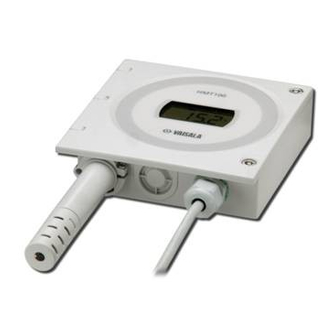
Chapter 2 __________________________________________________________ Product Overview HMT100 Transmitter Components side view with optional display without display 0505-169. 0505-170 Figure 1 Fixed Probe Model The following numbers refer to Figure 1 above: Transmitter cover Probe cover 0505-338 Figure 2 Remote Probe Model... - Page 14 User's Guide ______________________________________________________________________ This page intentionally left blank. 12 _______________________________________________________________ M210701EN-A...
-
Page 15: Chapter 3 Installation
Chapter 3 _______________________________________________________________ Installation CHAPTER 3 INSTALLATION Mounting Wall Mounting With Plastic Wall Assembly Plate (Provided) Attach the wall assembly plate to the wall with two screws. Press the transmitter down so that it slides down along the rails of the mounting plate. 0505-171 Figure 3 Plastic Wall Assembly Plate... -
Page 16: With Optional Aluminium Wall Installation Plate
User's Guide ______________________________________________________________________ With Optional Aluminium Wall Installation Plate Attach the aluminium plate to the wall. Attach the plastic wall assembly plate (provided) to the aluminium plate with two screws. Press the transmitter down so that it slides down along the rails of the wall assembly plate. -
Page 17: Installation With Rain Shield
Chapter 3 _______________________________________________________________ Installation Installation with Rain Shield The rain shield with installation kit includes a metal mounting plate and a rain shield for the transmitter. Vaisala order code: 215109. 050505-340 Figure 5 HMT100 Installation with Rain Shield Fasten the metal mounting plate to the wall or pole with screws (see Figure 5 above). -
Page 18: Installation With Radiation Shield
DTR502 with probe installation kit includes a rain/solar radiation shield DTR502 and a plastic installation support for the humidity probe. Vaisala order code: DTR502B. If you already have the DTR502 shield and need only the installation support for the probe, it is available with Vaisala order code: 210623. -
Page 19: Duct Installation Kit
Chapter 3 _______________________________________________________________ Installation Duct Installation Kit The duct installation kit includes a plastic pipe with a flange. Vaisala order code: 210710. To install the HMP100 probe with the duct installation kit, drill a hole to the duct wall, assemble the probe to the duct installation kit, slide the probe head through the hole, and attach the flange to the duct wall with four screws. -
Page 20: Probe Assembly With Duct Installation Kit
User's Guide ______________________________________________________________________ Probe Assembly with Duct Installation Kit 0505-177 Figure 8 Assembly of the Humidity Probe with the Duct Installation Kit The following numbers refer to Figure 8 above: HMP100 Duct installation kit Probe cable Slide the probe cable through the duct installation kit plastic pipe. -
Page 21: Connections
The following numbers refer to Figure 9 on page 18: Mounting screw Tension screw HMP100 assembled in duct installation kit plastic pipe Connections 0505-179 Figure 10 HMT100 Connection Board The following numbers refer to Figure 10 above: Service port Adjustment buttons Jumpers Optional LCD Field wire terminals Connector for HMP100 Humidity Probe Open the transmitter cover by taking out the cover screws. -
Page 22: Figure 11 Isolated Current-Loop Wiring, Voltage Output Wiring
User's Guide ______________________________________________________________________ Connect the wires as indicated in Figure 11 and in Table 3 on page 20. Note that you must wire the transmitter according to the type of transmitter (specified at order time; 2-wire current output or 3-wire voltage output). CH1 + Us + 10...35V DC... -
Page 23: Chapter 4 Maintenance
Chapter 4 ______________________________________________________________ Maintenance CHAPTER 4 MAINTENANCE This chapter provides information that is needed in basic maintenance of the product. Replacing the HUMICAP® Sensor Fixed Probe Model The end of the plastic probe cover is detachable. Carefully turn the end about 1/6 of a turn to loosen it. Remove the end of the probe cover and the filter. -
Page 24: Removing And Fastening The Probe
User's Guide ______________________________________________________________________ Removing and Fastening the Probe Fixed Probe Model Remove and replace the probe as follows: Loosen the plastic probe cover by carefully turning it counter clock wise. Remove the probe cap and O-ring. Remove the probe cover. The probe is now exposed. Unscrew the small sleeve that is securing the probe in place and pull out the probe. -
Page 25: Calibration And Adjustment
See contact information on page 39. It is also possible to remove the HMP100 probe and replace it with a new one. The old probe can be adjusted using another HMT100 transmitter body, if you have one available. -
Page 26: Relative Humidity Adjustment Using The Push-Buttons
User's Guide ______________________________________________________________________ Relative Humidity Adjustment Using the Push-Buttons 0505-182 Figure 14 Adjustment Buttons A simple push-button adjustment is carried out using two relative humidity references: 11.3 % RH (LiCl) and 75.5 % RH (NaCl). To carry out the adjustment, follow the instructions below: Remove the probe cover and the filter. -
Page 27: Adjustment With Hm70
HM70's connector ports located on the bottom of the indicator (see Figure 15 above). Turn on both devices (or just the HM70 if HMT100 is on continuously). The reading of the transmitter is shown on the top or middle row of the indicator display, depending on which connector port the connection cable is connected to. -
Page 28: Field Checking And Adjustment Using A Calibrated Reference Probe
User's Guide ______________________________________________________________________ Press to start adjustment. Check the environment settings if needed. Otherwise press Continue according to the directions of the desired adjustment method. Field Checking and Adjustment Using a Calibrated Reference Probe Follow steps 1 to 7 on page 25 and continue as follows: Check that the probes are located in equal conditions and wait until the readings have stabilized (may take 30 minutes or more). -
Page 29: Two-Point Adjustment Using A Calibrator
Chapter 4 ______________________________________________________________ Maintenance 0505-185 Figure 16 Example of the MI70 Adjustment Menu Press when the reading has stabilized in the reference READY condition (may take 30 minutes or more). You can follow the stabilization from the display. GRAPH 0505-186 Figure 17 Example of the MI70 Adjustment Mode Graph Display... -
Page 30: Licl-Nacl Adjustment
User's Guide ______________________________________________________________________ Enter the correct reference value in the first condition with the arrow buttons. Press Remove the probe from the first reference conditions and insert the probe head into the higher humidity reference condition. Press when the reading has stabilized in the second READY reference condition (may take 30 minutes or more). -
Page 31: Adjustment With Hmi41
Turn off the MI70 and detach the connection cable. Adjustment with HMI41 You can check and adjust the HMT100 relative humidity measurement with the HMI41 indicator and HMP41/45/46 probes. A HMI41-connection cable is needed, Vaisala order code: 25917ZZ. -
Page 32: Connections And Selecting The Calibrator Function
▲ and ▼. When the baud rate is correct, press , and the serial communications settings display appears. ENTER The correct settings for HMT100 series are: N, 8, 1. If needed, change the settings with buttons ▲ and ▼ until they are correct, press... -
Page 33: Offset And Gain Adjustments
Connect the 25917ZZ HMI41-connection cable to the SERVICE connector on the HMT100 motherboard (see Figure 10 on PORT page 19). Connect the other end of the connection cable to the connector located on the bottom of the HMI41 indicator (see Figure 18 on page 29). -
Page 34: Hmi41 As A Terminal
User's Guide ______________________________________________________________________ Numbers on the first line indicate the transmitter reading, and the numbers on the second line indicate the reference probe reading. Let the readings stabilize (may take 30 minutes or more). If you prefer, you can change the display to show the difference in the readings. - Page 35 Chapter 4 ______________________________________________________________ Maintenance The numbers on the first line indicate the transmitter reading, and the numbers on the second line indicate the HMI41 probe reading. Let the readings stabilize and press . The following display MODE appears: The HMI41 now works only as a terminal for setting the humidity reading.
-
Page 36: Troubleshooting
User's Guide ______________________________________________________________________ Troubleshooting Table 4 presents a summary of a few error messages that may appear during adjustment with the HMI41. Table 4 Common Problems During Adjustment and Their Remedies Error Message Probable Cause Remedy This message may Perform the adjustment appear for example if again. -
Page 37: Analog Output Tests
Chapter 4 ______________________________________________________________ Maintenance Analog Output Tests The HMT100 Humidity and Temperature Transmitter has a built-in software function for testing the analog outputs. To test the outputs, do the following: Make sure the transmitter is not in adjustment mode. Press the 75 % adjustment button (see Figure 14 on page 24). - Page 38 User's Guide ______________________________________________________________________ This page intentionally left blank. 36 _______________________________________________________________ M210701EN-A...
-
Page 39: Chapter 5 Troubleshooting
This chapter describes error messages, their probable causes and remedies, and contact information. Error Mode In error mode the analog outputs switch to I_OUT = 23 mA. Technical Support For technical questions, contact the Vaisala technical support: E-mail helpdesk@vaisala.com +358 9 8949 2790 Return Instructions If the product needs repair, please follow the instructions below to speed up the process and avoid extra costs. - Page 40 User's Guide ______________________________________________________________________ - When did it fail (date, immediately / after a while / periodically / randomly)? - How many failed (only one defect / other same or similar defects / several failures in one unit)? - What was connected to the product and to which connectors? - Input power source type, voltage and list of other items (lighting, heaters, motors etc.) that were connected to the same power output.
-
Page 41: Vaisala Service Centers
Vaisala Oyj Contact person / Division Vanha Nurmijärventie 21 FIN-01670 Vantaa Finland or to the Vaisala Service Center in your region (see contact information below) Vaisala Service Centers NORTH AMERICAN SERVICE CENTER Vaisala Inc., 10-D Gill Street, Woburn, MA 01801-1068, USA. - Page 42 User's Guide ______________________________________________________________________ This page intentionally left blank. 40 _______________________________________________________________ M210701EN-A...
-
Page 43: Chapter 6 Technical Data
Chapter 6 ____________________________________________________________ Technical Data CHAPTER 6 TECHNICAL DATA This chapter provides the technical data of the product. Specifications Table 5 Relative Humidity Measurement Specifications Property Description / Value Measurement range 0...100 %RH Accuracy against factory standards including non-linearity, hysteresis, and repeatability at +15...+25°C ±1.7 %RH (0...90 %RH) -
Page 44: Figure 19 Accuracy Of Temperature Measurement
User's Guide ______________________________________________________________________ 0505-247 Figure 19 Accuracy of Temperature Measurement Table 7 Dewpoint Temperature (Calculated) Measurement Specifications Property Description / Value Measuring range -20...+80 °C (+4...176 °F) Accuracy see Table 8 below Table 8 Accuracy of Dewpoint Temperature Measurement Relative humidity Temp. -
Page 45: Table 10 Inputs And Outputs
Chapter 6 ____________________________________________________________ Technical Data Table 10 Inputs and Outputs Property Description / Value Current output version Two-wire output signal 4...20 mA (loop powered) External loop load with 4 ... 20 mA 10 ... 35 VDC (R = 0 ohms) 20 ... -
Page 46: Table 12 Options And Accessories
User's Guide ______________________________________________________________________ Table 12 Options and Accessories Description Order Code Sensor head HMP100 HMP100 Humidity sensor Humicap180 T-sensor PT1000 18921 Filter plastic grid + membrane DRW010525 Sintered stainless steel filter HM46670SP Extension cable 10m DRW220095 Probe cable 0.1 m HMP50Z010SP Probe cable 3m HMP50Z300SP... -
Page 47: Dimensions In Mm (Inches)
Chapter 6 ____________________________________________________________ Technical Data Dimensions in mm (inches) 0505-188 Figure 20 Dimensions HMT100 Fixed Probe Model VAISALA____________________________________________________________________ 45... -
Page 48: Figure 21 Dimensions Hmt100 Remote Probe Model
User's Guide ______________________________________________________________________ 119 4.69 33.5 1.32 Ø 12 0.47 0505-189 Figure 21 Dimensions HMT100 Remote Probe Model 46 _______________________________________________________________ M210701EN-A...