
Related Manuals for Comtrend Corporation CT-5361T


Summary of Contents for Comtrend Corporation CT-5361T
-
Page 1: User Manual
CT-5361T Wireless ADSL2+ Router User Manual Version A3.6, October 3, 2008 261056-044... - Page 2 Copyright Copyright©2008 Comtrend Corporation. All rights reserved. The information contained herein is proprietary to Comtrend Corporation. No part of this document may be translated, transcribed, reproduced, in any form, or by any means without prior written consent of Comtrend Corporation.
-
Page 3: Table Of Contents
Table of Contents CHAPTER 1 INTRODUCTION......................4 1.1 F ............................4 EATURES 1.2 A ...........................4 PPLICATION CHAPTER 2 INSTALLATION......................5 2.1 H ...........................5 ARDWARE ETUP 2.2 USB D ................6 EVICE RIVER NSTALLATION 2.3 USB D OS) ................9 RIVER ANUAL NSTALLATION 2.4 LED I ...........................14 NDICATORS CHAPTER 3 WEB USER INTERFACE....................15... - Page 4 CHAPTER 7 WIRELESS........................69 7.1 B ............................69 ASIC 7.2 S ............................70 ECURITY 7.3 MAC F ..........................72 ILTER 7.4 W .........................73 IRELESS RIDGE 7.5 A ............................74 DVANCED 7.6 Q ........................76 UALITY OF ERVICE 7.7 S ..........................77 TATION CHAPTER 8 DIAGNOSTICS......................78 CHAPTER 9 MANAGEMENT ......................80 9.1 S ............................80 ETTINGS...
-
Page 5: Chapter 1 Introduction
Chapter 1 Introduction The CT-5361T Wireless ADSL2+ Router is designed for both residential and business applications that require wired and wireless connectivity to an ADSL broadband network. In terms of connectivity, it comes fully equipped with four Fast Ethernet ports , a single USB port and an integrated 802.11g WiFi WLAN Access Point (AP) for wireless connectivity. -
Page 6: Chapter 2 Installation
2.4 LED Indicators for details). NOTE: If pressed down for more than 12 seconds, the CT-5361T will go into a firmware update state (CFE boot mode). The firmware can then be updated using an Internet browser pointed to the default IP address. -
Page 7: Usb Device Driver Auto-Run Installation
Connection to USB Before connecting the CT-5361T to a PC with the USB cable, the USB device driver must first be installed. See the sections 2.2 and 2.3 for detailed instructions. Connection to LAN Use RJ45 cable to connect up to four network devices. These ports are auto-sensing MDI/X and either straight-through or crossover cable can be used. - Page 8 STEP 2: The following window will display. Click Next to continue. STEP 3: When the window displays as below, wait for the drivers to fully install. STEP 4: Click Finish, when the window displays as below.
- Page 9 STEP 5: Installation is complete. Now connect the device to your PC using standard USB cable.
-
Page 10: Usb Driver Manual Installation (64Bit Os)
2.3 USB Driver Manual Installation (64bit OS) Before connecting this router to a PC with USB, the correct drivers must be installed. Follow the procedure below to manually install the 64-bit USB driver STEP 1: Connect the USB port to the PC by plugging the flat connector of a standard USB cable into your PC and plugging the square connector into the device. - Page 11 NOTE: This window won’t display if the USB Driver has been previously installed. In this case, contact technical support for assistance. STEP 3: Insert the installation CD. NOTE: If you see the autostart menu (as shown in step 1 of previous section) CLICK - and continue with the manual installation process.
- Page 12 STEP 4: Select the location of the file using the Browse button, as shown above. Normally, the file is on the CD-ROM shipped with the device. STEP 5: Locate the Vista folder, and click OK. STEP 6: When the window displays as below, click Next, and then wait.
- Page 14 STEP 7: Click the Finish button when the window displays as below. STEP 8: Installation is complete. You can now use the USB connection.
-
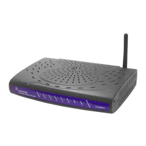
Page 15: Led Indicators
2.4 LED Indicators The front panel LED indicators are shown below and explained in the following table. This information can be used to check the status of the device and its connections. Color Mode Function POWER Green The device is powered up. The device is powered down. -
Page 16: Chapter 3 Web User Interface
Chapter 3 Web User Interface This section describes how to access the device via the web user interface (WUI) using an Internet browser such as Internet Explorer (version 5.0 and later). 3.1 Default Settings The factory default settings of this device are summarized below. LAN IP address: 192.168.1.1 LAN subnet mask: 255.255.255.0 Administrative access (username: root , password: 12345) -
Page 17: Ip Configuration
3.2 IP Configuration STATIC IP MODE To access router settings, your PC must have a static IP address within the 192.168.1.x subnet. Follow the steps below to configure your PC IP address to use subnet 192.168.1.x. The following steps assume you are running Windows XP. STEP 1: From the Network Connections window, open Local Area Connection (You may also access this screen by double-clicking the Local Area Connection icon on your taskbar). -
Page 18: Login Procedure
DHCP MODE Set your PC to DHCP mode by selecting Obtain an IP address automatically in the Internet Protocol Properties dialog box, as shown below. 3.3 Login Procedure Perform the following steps to login to the web user interface. NOTE: The default settings can be found in 3.1 Default Settings. - Page 19 Click OK to continue. NOTE: The login password can be changed later (see 9.6.3 Passwords) STEP 3: After successfully logging in for the first time, you will reach this screen. NOTE1: If a PVC connection already exists then this Quick Setup screen will be bypassed and the Device Info –...
-
Page 20: Chapter 4 Quick Setup
If the service provider provides PPPoE service, then the connection selection depends on whether the LAN-side device (typically a PC) is running a PPPoE client or whether the CT-5361T is to run the PPPoE client. The CT-5361T can support both cases simultaneously. -
Page 21: Auto Quick Setup
Step 2: Click Next to start the setup process. Follow the online instructions to complete the setting. This procedure will skip some advanced setup procedures (such as PVC index and encapsulation selection). Step 3: After the setup is complete the CT-5361T will reboot. NOTE: After the device reboots, the Device Info –... -
Page 22: Manual Quick Setup
4.2 Manual Quick Setup STEP 1: Click Quick Setup and un-tick the DSL Auto-connect checkbox enable manual configuration of the connection type. Un-tick this checkbox to enable manual setup and display the following screen. STEP 2: Adjust the VPI/VCI settings for the connection you wish to establish. You may also Enable Quality of Service (QoS) with its checkbox STEP 3: On this screen, you can choose the connection type and select the appropriate encapsulation mode. - Page 23 Click Next to continue… NOTE: The subsections that follow continue the ATM PVC setup procedure. Enter the appropriate settings for your service. Choosing different connection types will lead to a different sequence of setup screens.
-
Page 24: Ppp Over Atm (Pppoa) And Ppp Over Ethernet (Pppoe)
For Authentication Method, choose from AUTO, PAP, CHAP, and MSCHAP. Dial on Demand The CT-5361T can be configured to disconnect if there is no activity for a period of time by selecting the Dial on demand check box. When the checkbox is ticked, you must enter an inactivity timeout period of 1 to 4320 minutes. - Page 25 device has only a single IP address to assign to a LAN device. NAT and firewall are disabled when this option is selected. The device becomes the default gateway and DNS server to the PC through DHCP using the LAN interface IP address. The device extends the IP subnet at the remote service provider to the LAN PC.
- Page 26 Service Name: This is the WAN Service label. STEP 6: Upon completion, click Next. The following screen appears. This screen allows for the configuration of the CT-5361T LAN interface IP address, subnet mask and DHCP server. To auto-assign IP addresses, DNS server and default gateway to other LAN devices, select the Enable DHCP server radio box.
- Page 27 The Web UI will not respond until the system is brought up again. After the system is up, the Web UI will refresh to the Device Info screen automatically. The CT-5361T is ready for operation when the front panel LED indicators display as described in section 2.4 LED...
-
Page 28: Mac Encapsulation Routing (Mer)
4.2.2 MAC Encapsulation Routing (MER) STEP 4: Enter the WAN IP settings as provided by your ISP. DHCP can be enabled if the Obtain an IP address automatically checkbox checked. Configuring the default gateway or the DNS with static values will disable the automatic assignment from DHCP or other WAN connection. - Page 29 Service Name is user-defined. STEP 6: Upon completion, click Next. The following screen appears. This screen allows for the configuration of the CT-5361T LAN interface IP address, subnet mask and DHCP server. To auto-assign IP addresses, DNS server and default gateway to LAN devices, select the Enable DHCP server radio box. You must also enter the start and end IP address and DHCP leased time.
- Page 30 The Web UI will not respond until the system is brought up again. After the system is up, the Web UI will refresh to the Device Info screen automatically. The CT-5361T is ready for operation when the front panel LED indicators display as described in section 2.4 LED...
-
Page 31: Ip Over Atm
4.2.3 IP Over ATM STEP 4: Enter the WAN IP settings as provided by your ISP. Since DHCP is not supported over IPoA, the default gateway settings and DNS server addresses must be entered here. These should be provided by your ISP. STEP 5: Click Next to display the following screen. - Page 32 Service Name is user-defined. STEP 6: Upon completion, click Next. The following screen appears. This screen allows for the configuration of the CT-5361T LAN interface IP address, subnet mask and DHCP server. To auto-assign IP addresses, DNS server and default gateway to LAN devices, select the Enable DHCP server radio box. You must also enter the start and end IP address and DHCP leased time.
- Page 33 The Web UI will not respond until the system is brought up again. After the system is up, the Web UI will refresh to the Device Info screen automatically. The CT-5361T is ready for operation when the front panel LED indicators display as described in section 2.4 LED...
-
Page 34: Bridging
Enter the IP address and subnet mask for the LAN interface. These settings are used to manage the CT-5361T. In bridge mode, there is no WAN IP address and therefore no remote access to the router for technical support or other purposes. - Page 35 The Web UI will not respond until the system is brought up again. After the system is up, the Web UI will refresh to the Device Info screen automatically. The CT-5361T is ready for operation when the front panel LED indicators display as described in section 2.4 LED...
-
Page 36: Chapter 5 Device Information
Chapter 5 Device Information The web user interface is divided into two windowpanes, the main menu (at left) and the display screen (on the right). The main menu has the several options and selecting each of these options opens a submenu with more selections. NOTE: The menu items shown are based upon the configured connection and user account privileges. -
Page 37: Wan
5.1 WAN Select WAN from the Device Info submenu to display the configured PVC(s). Heading Description VPI/VCI ATM VPI (0-255) / VCI (32-65535) Con. ID WAN connection ID number Category ATM service category Service Name of the WAN connection Interface Name of the interface for WAN Protocol Shows the connection type... -
Page 38: Wan Statistics
Heading Description Interface LAN interfaces Received/Transmitted: - Bytes Number of Bytes - Pkts Number of Packets - Errs Number of packets with errors - Drops Number of dropped packets 5.2.2 WAN Statistics Heading Description Service WAN service label VPI/VCI ATM Virtual Path/Channel Identifiers Protocol Connection type (e.g. -
Page 39: Atm Statistics
5.2.3 ATM statistics The following figure shows the ATM statistics screen. ATM Interface Statistics Heading Description In Octets Number of received octets over the interface Out Octets Number of transmitted octets over the interface In Errors Number of cells dropped due to uncorrectable HEC errors In Unknown Number of received cells discarded during cell header validation, including cells with unrecognized VPI/VCI values, and cells with... - Page 40 In Errors Number of received AAL5/AAL0 CPCS PDUs received that contain an error. These errors include CRC-32 errors. Out Errors Number of received AAL5/AAL0 CPCS PDUs that could not be transmitted due to errors. In Discards Number of received AAL5/AAL0 CPCS PDUs discarded due to an input buffer overflow condition.
-
Page 41: Adsl Statistics
5.2.4 ADSL Statistics The following figure shows the ADSL Statistics screen in G.Dmt mode. Click the Reset Statistics button to refresh this screen. - Page 42 Field Description Mode G.Dmt, G.lite, T1.413, ADSL2, ADSL2+ Type Channel type Interleave or Fast Line Coding Trellis On/Off Status Lists the status of the DSL link Link Power State Link output power state. SNR Margin (dB) Signal to Noise Ratio (SNR) margin Attenuation (dB) Estimate of average loop attenuation in the downstream direction.
- Page 43 Within the ADSL Statistics window, a Bit Error Rate (BER) test can be started using the ADSL BER Test button. A small window will open when the button is pressed; it will appear as shown below. Click Start to start the test or Close. If the test is successful, the pop-up window will display as follows.
-
Page 44: Route
5.3 Route Choose Route to display the routes that the CT-5361T has found. Field Description Destination Destination network or destination host Gateway Next hub IP address Subnet Mask Subnet Mask of Destination Flag U: route is up !: reject route... -
Page 45: Arp
5.4 ARP Click ARP to display the ARP information. Field Description IP address Shows IP address of host pc Flags Complete, Incomplete, Permanent, or Publish HW Address Shows the MAC address of host pc Device Shows the connection interface 5.5 DHCP Click DHCP to display all DHCP Leases. -
Page 46: Chapter 6 6.1 Wan
Chapter 6 Advanced Setup This chapter explains the following screens: 6.1 WAN 6.6 Routing 6.2 LAN 6.7 DNS 6.3 NAT 6.8 DSL 6.4 Security 6.9 Port Mapping 6.5 Quality of Service 6.10 Certificate 6.1 WAN This screen allows for the configuration of WAN interfaces. To Add a new WAN connection, click the Add button. -
Page 47: Lan
6.2 LAN From this screen, LAN interface settings can be configured. NOTE: NAT is enabled so UPnP is shown above (see underlined notes below). Consult the field descriptions below for more details. IP Address: Enter the IP address for the LAN port. Subnet Mask: Enter the subnet mask for the LAN port. - Page 48 DHCP Server Relay: Enable with checkbox and enter DHCP Server IP address. This allows the Router to relay the DHCP packets to the remote DHCP server. The remote DHCP server will provide the IP address. This option is hidden if NAT is enabled To configure a secondary IP address, tick the checkbox outlined (in RED) below.
-
Page 49: Nat
6.3 NAT To display this option, NAT must be enabled in at least one PVC shown on the Advanced Setup - WAN screen. (NAT is not an available option in Bridge mode) 6.3.1 Virtual Servers Virtual Servers allow you to direct incoming traffic from the WAN side (identified by Protocol and External port) to the Internal server with private IP addresses on the LAN side. -
Page 50: Port Triggering
Consult the table below for field and header descriptions. Field/Header Description Select a Service User should select the service from the list. Custom Server User can enter the name of their choice. Server IP Address Enter the IP address for the server. External Port Start Enter the starting external port number (when you select Custom Server). - Page 51 Consult the table below for field and header descriptions. Field/Header Description Select an Application User should select the application from the list. Custom Application User can enter the name of their choice. Trigger Port Start Enter the starting trigger port number (when you select custom application).
-
Page 52: Dmz Host
6.3.3 DMZ Host The DSL router will forward IP packets from the WAN that do not belong to any of the applications configured in the Virtual Servers table to the DMZ host computer. To Activate the DMZ host, enter the DMZ host IP address and click Save/Apply. To Deactivate the DMZ host, clear the IP address field and click Save/Apply. -
Page 53: Security
6.4 Security To display this function, you must enable the firewall feature in WAN Setup. For detailed descriptions, with examples, please consult Appendix A: Firewall. 6.4.1 IP Filtering This screen sets filter rules that limit IP traffic (Outgoing/Incoming). Multiple filter rules can be set and each applies at least one limiting condition. - Page 54 Consult the table below for field descriptions. Field Description Filter Name The filter rule label Protocol TCP, TCP/UDP, UDP, or ICMP. Source IP address Enter source IP address. Source Subnet Mask Enter source subnet mask. Source Port (port or port:port) Enter source port number or range.
-
Page 55: Mac Filtering
Each network device has a unique 48-bit MAC address. This can be used to filter (block or forward) packets based on the originating device. MAC filtering policy and rules for the CT-5361T can be set according to the following procedure. The MAC Filtering Global Policy is defined as follows. FORWARDED means that all MAC layer frames will be FORWARDED except those matching the MAC filter rules. - Page 56 Choose Add or Remove to configure MAC filtering rules. The following screen will appear when you click Add. Create a filter to identify the MAC layer frames by specifying at least one condition below. If multiple conditions are specified, all of them must be met.
-
Page 57: Parental Control
6.4.3 Parental Control This feature restricts access from a LAN device to an outside network through the device on selected days at certain times. Make sure to activate the Internet Time server synchronization as described in section 9.5 Internet Time, so that the scheduled times match your local time. -
Page 58: Quality Of Service
6.5 Quality of Service NOTE: QoS must be enabled in at least one PVC to display this option. (see Advanced Setup - WAN for further instructions). Choose Add to configure network traffic classes. The following screen will display. Field Description Traffic Class Name Enter name for traffic class. - Page 59 Mark IP Type Of Service Normal Service, Minimize Cost, Maximize Reliability, Maximize Throughput, Minimize Delay Mark 802.1p if 802.1q is Select between 0-7. The higher the digit shows enabled on WAN the higher the priority. SET-1 Physical LAN Port Select between ENET(1-4) and USB Protocol TCP, TCP/UDP, UDP, or ICMP.
-
Page 60: Routing
Assign Differentiated Services The selected Code Point gives the Code Point (DSCP) Mark corresponding priority to the packets that satisfies the rules set below. Source MAC Address A packet belongs to SET-1, if a binary-AND of its source MAC address with the Source MAC Mask is equal to the binary-AND of the Source MAC Mask and this field. -
Page 61: Static Route
6.6.2 Static Route This option allows for the configuration of static routes. Click Add to create a new static route. Click Remove to delete the selected static route. Click the Add button to display the following screen. Enter Destination Network Address, Subnet Mask, Gateway IP Address, and/or WAN Interface. -
Page 62: Dns
You must reboot the router to make the new configuration effective. 6.7.2 Dynamic DNS The Dynamic DNS service allows you to map a dynamic IP address to a static hostname in any of many domains, allowing the CT-5361T to be more easily accessed from various locations on the Internet. - Page 63 To add a dynamic DNS service, click Add. The following screen will display. Consult the table below for field descriptions. Field Description D-DNS provider Select a dynamic DNS provider from the list Hostname Enter the name for the dynamic DNS server Interface Select the interface (PVC) from the list Username...
-
Page 64: Dsl
6.8 DSL The DSL Settings screen allows for the selection of DSL modulation modes. For optimum performance, the modes selected should match those of your ISP. DSL Mode Data Transmission Rate - Mbit/s (Megabits per second) G.Dmt Downstream: 12 Mbit/s Upstream: 1.3 Mbit/s G.lite Downstream:... -
Page 65: Port Mapping
6.9 Port Mapping Port Mapping supports multiple ports to PVC and bridging groups. Each group will perform as an independent network. To use this feature, you must create mapping groups with appropriate LAN and WAN interfaces using the Add button. The Remove button acts to remove mapping groups and return the ungrouped interfaces to the Default group. - Page 66 To create a group from the list, first enter the group name and then select from the available interfaces on the list. Automatically Add Clients With the Following DHCP Vendor IDs: Add support to automatically map LAN interfaces to PVC's using DHCP vendor ID (option 60).
-
Page 67: Certificate
6.10 Certificate A certificate is a public key, attached with its owner’s information (company name, server name, personal real name, contact e-mail, postal address, etc) and digital signatures. There will be one or more digital signatures attached to the certificate, indicating that these entities have verified that this certificate is valid. - Page 68 Field Description Certificate Name A user-defined name for the certificate. Common Name Usually, the fully qualified domain name for the machine. Organization Name The exact legal name of your organization. Do not abbreviate. State/Province Name The state or province where your organization is located. It cannot be abbreviated.
-
Page 69: Trusted Ca
6.10.2 Trusted CA CA is an abbreviation for Certificate Authority, which is a part of the X.509 system. It is itself a certificate, attached with the owner information of this certificate authority; but its purpose is not encryption/decryption. Its purpose is to sign and issue certificates, in order to prove that these certificates are valid. -
Page 70: Chapter 7 Wireless
Chapter 7 Wireless The Wireless menu provides access to the wireless options discussed below. 7.1 Basic The Basic option allows you to configure basic features of the wireless LAN interface. You can enable or disable the wireless LAN interface, hide the network from active scans, set the wireless network name (also known as SSID) and restrict the channel set based on country requirements. -
Page 71: Security
Country A drop-down menu that permits worldwide and specific national settings. Each county listed below enforces specific regulations limiting channel range: US= worldwide, Japan=1-14, Jordan= 10-13, Israel= 1-13 Wireless The Guest SSID (Virtual Access Point) can be enabled by selecting Guest the Enable Wireless Guest Network checkbox . - Page 72 Select SSID Select the wireless network name from the drop-down box. SSID stands for Service Set Identifier. All stations must be configured with the correct SSID to access the WLAN. If the SSID does not match, that user will not be granted access.
-
Page 73: Mac Filter
WEP Encryption This option specifies whether data sent over the network is encrypted. The same network key is used for data encryption and network authentication. Four network keys can be defined although only one can be used at any one time. Use the Current Network Key list box to select the appropriate network key. -
Page 74: Wireless Bridge
After clicking the Add button, the following screen appears. Enter the MAC address in the box provided and click Save/Apply. 7.4 Wireless Bridge This screen allows for the configuration of wireless bridge features of the WLAN interface. See the table beneath for detailed explanations of the various options. Click Save/Apply to implement new configuration settings. -
Page 75: Advanced
7.5 Advanced The Advanced screen allows you to configure advanced features of the wireless LAN interface. You can select a particular channel on which to operate, force the transmission rate to a particular speed, set the fragmentation threshold, set the RTS threshold, set the wakeup interval for clients in power-save mode, set the beacon interval for the access point, set XPress mode and set whether short or long preambles are used. - Page 76 Fragmentation A threshold, specified in bytes, that determines whether packets Threshold will be fragmented and at what size. On an 802.11 WLAN, packets that exceed the fragmentation threshold are fragmented, i.e., split into, smaller units suitable for the circuit size. Packets smaller than the specified fragmentation threshold value are not fragmented.
-
Page 77: Quality Of Service
7.6 Quality of Service WMM provides advanced quality of service (QoS) features for Wi-Fi networks to improve the end-user experience by prioritizing audio, video and voice traffic and optimizing the way shared network resources are allocated among competing applications. To enable WMM, select Enabled in the WMM (Wi-Fi Multimedia) drop down list box. -
Page 78: Station Info
7.7 Station Info This page shows authenticated wireless stations and their status. Click the Refresh button to update the list of stations in the WLAN. Heading Description BSSID The BSSID is a 48-bit identity used to identify a particular BSS (Basic Service Set) within an area. In Infrastructure BSS networks, the BSSID is the MAC (Media Access Control) address of the AP (Access Point);... -
Page 79: Chapter 8 Diagnostics
ADSL Pass: Indicates that the CT-5361T has detected a DSL signal Synchronization from the telephone company. Fail: Indicates that the CT-5361T does not detect a DSL signal from the telephone company. Diagnostics screens for various connection types are provided below. - Page 80 PPPoE Connection Bridge Connection...
-
Page 81: Chapter 9 Management
Chapter 9 Management The Management menu has the following maintenance functions and processes: 9.1 Settings 9.5 Internet Time 9.2 System Log 9.6 Access Control 9.3 SNMP Agent 9.7 Update Software 9.4 TR-069 Client 9.8 Save and Reboot 9.1 Settings This includes Backup Settings, Update... -
Page 82: Restore Default
PC IP configuration to match your new settings. NOTE: This entry has the same effect as the Reset button. The CT-5361T board hardware and the boot loader support the reset to default. If the Reset button is continuously pressed for more than 5 seconds, the boot loader... -
Page 83: System Log
“Emergency” down to this configured level will be recorded to the log buffer on the CT-5361T SDRAM. When the log buffer is full, the newer event will wrap up to the top of the log buffer and overwrite the old event. -
Page 84: Snmp Agent
By default, the log level is “Debugging”, which is the lowest critical level. The log levels are defined as follows: Emergency = system is unusable Alert = action must be taken immediately Critical = critical conditions Error = Error conditions Warning = normal but significant condition Notice= normal but insignificant condition Informational= provides information for reference... -
Page 85: Tr-069 Client
9.4 TR-069 Client WAN Management Protocol (TR-069) allows an Auto-Configuration Server (ACS) to perform auto-configuration, provision, collection, and diagnostics to this device. Option Description Inform Disable/Enable TR-069 client on the CPE. Inform Interval The duration in seconds of the interval for which the CPE MUST attempt to connect with the ACS and call the Inform method. -
Page 86: Internet Time
Protocol. This username is used only for HTTP-based authentication of the CPE. ACS Password Password used to authenticate the CPE when making a connection to the ACS using the CPE WAN Management Protocol. This password is used only for HTTP-based authentication of the CPE. -
Page 87: Access Control
9.6 Access Control 9.6.1 Services This option controls the access services over the LAN or WAN. These services include FTP, HTTP, ICMP, SNMP, SSH, TELNET, TFTP, and TR69C (TR-069 client). Enable a service by ticking the corresponding checkbox under LAN or WAN. NOTES - 1. -
Page 88: Passwords
Passwords This screen is used to configure the user account access passwords for the device. Access to the CT-5361T is controlled through the following three user accounts: root - this has unrestricted access to change and view the configuration. support - used for remote maintenance and diagnostics of the router user - this has limited access. -
Page 89: Update Software
NOTE: Passwords must be 16 characters or less. 9.7 Update Software This option allows for firmware upgrades from a locally stored file. Step 1: Obtain an updated software image file from your ISP. Step 2: Enter the path and filename of the firmware image file in the Software File Name field or click the Browse button to locate the image file. -
Page 90: Save And Reboot
9.8 Save and Reboot To save the current configuration and reboot the router, click Save/Reboot. NOTE: You may need to close the browser window and wait for 2 minutes before reopening it. It may also be necessary, to reset your PC IP configuration. -
Page 91: Appendix A: Firewall
Appendix A: Firewall STATEFUL PACKET INSPECTION Refers to an architecture, where the firewall keeps track of packets on each connection traversing all its interfaces and makes sure they are valid. This is in contrast to static packet filtering which only examines a packet based on the information in the packet header. - Page 92 Example 2: Filter Name : Out_Filter2 Protocol : UDP Source Address : 192.168.1.45 Source Subnet Mask : 255.255.255.0 Source Port : 5060:6060 Dest. Address : 172.16.13.4 Dest. Subnet Mask : 255.255.255.0 Dest. Port : 6060:7070 This filter will drop all UDP packets coming from the LAN with IP Address / Subnet Mask of 192.168.1.45/24 and a source port range of 5060 to 6060, destined to 172.16.13.4/24 and a destination port range of 6060 to 7070.
- Page 93 Example 2: Filter Name : In_Filter2 Protocol : UDP Source Address : 210.168.219.45 Source Subnet Mask : 255.255.0.0 Source Port : 5060:6060 Dest. Address : 192.168.1.45 Dest. Sub. Mask : 255.255.255.0 Dest. Port : 6060:7070 This rule will ACCEPT all UDP packets coming from WAN interface mer_0_35/nas_0_35 with IP Address/Subnet Mask 210.168.219.45/16 and a source port in the range of 5060 to 6060, destined to 192.168.1.45/24 and a destination port in the range of 6060 to 7070.
- Page 94 DAYTIME PARENTAL CONTROL This feature restricts access of a selected LAN device to an outside Network through the CT-5361T, as per chosen days of the week and the chosen times. User Name: Name of the Filter. Browser’s MAC Address: Displays MAC address of the LAN device on which the browser is running.
-
Page 95: Appendix B: Pin Assignments
Appendix B: Pin Assignments LINE PORT (RJ11) Definition Definition ADSL_TIP ADSL_RING LAN Port (RJ45) Definition Definition Transmit data+ Transmit data- Receive data- Receive data+... -
Page 96: Appendix C: Specifications
Appendix C: Specifications Hardware Interface RJ-11 X1 for ADSL2+, RJ-45 X 4 for LAN, USB X 1 for LAN, Reset Button X 1, Power Button X 1, Power Jack X 1, WiFi Antenna X 1 WAN Interface ITU-T G.994.1/G.992.5/G.992.3/G.992.2/G.992.1, ANSI T1.413 Issue 2 G.992.5 (ADSL2+) ..Downstream : 24 Mbps Upstream : 1.3 Mbps G.992.3 (ADSL2)...Downstream : 12 Mbps Upstream : 1.3 Mbps Auto-negotiation rate adaptation... - Page 97 Dimensions ........205 mm (W) x 48 mm (H) x 145 mm (D) Kit Weight = 1.3 kg (1*CT-5361T, 1*RJ11 cable, 1*RJ45 cable, 1*USB cable, 1*Power Adapter, 1*CD-ROM) Certifications..........FCC Part 15 class B, FCC Part 68 NOTE: Specifications are subject to change without notice...
-
Page 98: Appendix D: Ssh Client
Appendix D: SSH Client Unlike Microsoft Windows, Linux OS has a ssh client included. For Windows users, there is a public domain one called “putty” that can be downloaded from here: http://www.chiark.greenend.org.uk/~sgtatham/putty/download.html To access the ssh client you must first enable SSH access for the LAN or WAN from the Management Access Control Services menu in the web user interface.