HP ProCurve 6120G/XG Installation And Getting Started Manual
Hp procurve series 6120 blade switches installation and getting started guide
Hide thumbs
Also See for ProCurve 6120G/XG:
- Configuration manual (662 pages) ,
- Manual (606 pages) ,
- Management manual (222 pages)
Table of Contents
Advertisement
Quick Links
- 1 Hp Procurve 6120G/Xg Blade Switch
- 2 Accessing the Blade Switch from the Hp Bladesystem Onboard Administrator
- 3 Accessing the Blade Switch from the Ethernet Interface (in Band)
- 4 Getting Started with Switch Configuration
- 5 Recommended Minimal Configuration
- 6 Restoring the Factory Default Configuration
- Download this manual
Advertisement
Table of Contents
Troubleshooting

Related Manuals for HP ProCurve 6120G/XG


Summary of Contents for HP ProCurve 6120G/XG
- Page 1 ProCurve 5400zl Switches ProCurve Series 6120 Blade Switches Installation and Getting Started Guide Installation and Getting Started Guide...
- Page 3 HP shall not be liable for technical or editorial HP ProCurve 6120G/XG Blade Switch errors or omissions contained herein. HP ProCurve 6120XG Blade Switch Hewlett-Packard assumes no responsibility for the use or reliability of its software on equipment that is not furnished by Hewlett-Packard. Warranty See the Customer Support/Warranty booklet included with the product.
-
Page 5: Table Of Contents
Introducing the Switch ..........1 HP ProCurve 6120G/XG Blade Switch ......1 HP ProCurve 6120XG Blade Switch . - Page 6 Diagnosing the 6120G/XG with the LEDs ......24 Diagnostic Tips: ..........25 Diagnosing the 6120XG with the LEDs .
- Page 7 Straight-Through Twisted-Pair Cable for 10 Mbps or 100 Mbps Network Connections ..... . . 42 Cable Diagram ......... . . 42 Pin Assignments .
-
Page 9: Introducing The Switch
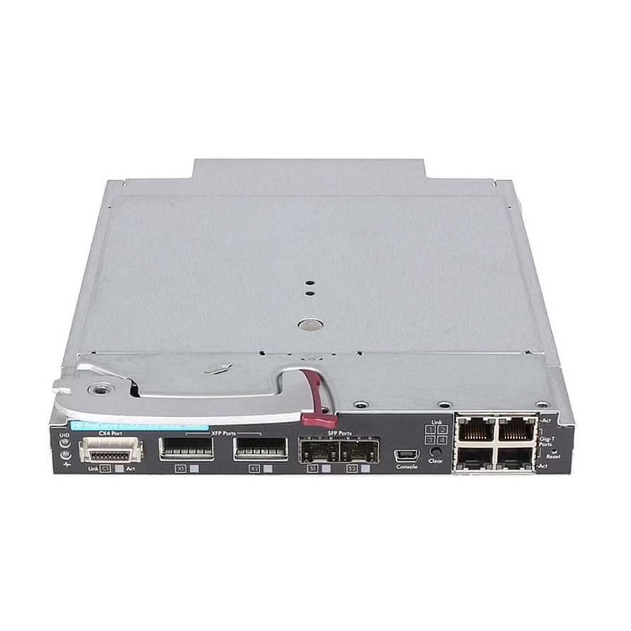
ProCurve switch CLI or web GUI. This port is disabled by default in the ProCurve switch factory default configuration. The 6120G/XG is perfectly suited for data centers in transition where a mix of 1Gb and 10Gb network connections are required. The 6120G/XG blade switch provides consistency and... - Page 10 Introducing the Switch Table 1. This product supports optional network connectivity with the following speeds and technologies: Speed Technology Cabling Transceiver form-factor and connector SFP (mini-GBIC) Connector Connector 1-Gbps 1000-SX Fiber (multimode) 1000-LX Fiber (multimode or single mode) 1000-T Copper (twisted- RJ-45 pair) 10-Gbps...
- Page 11 Introducing the Switch ➎ ➍ ➊ ➋ ➌ ➏ ➐ ➑ ➒ ➓ Figure 3. Switch LEDs Item LED Description Status Switch locator (UID) Blue = Switch ID selected Off = Switch ID not selected Switch status (health) Green = Normal operation Amber = Fault Off = Power off C1 port status...
-
Page 12: Hp Procurve 6120Xg Blade Switch
Introducing the Switch HP ProCurve 6120XG Blade Switch The HP ProCurve 6120XG Blade Switch is a blade switch for the HP BladeSystem c-Class enclosures. The 6120XG Blade Switch supports advanced Layer two switching. This switch can be used to build high speed switched networks between servers in the data center. Figure 4. - Page 13 Introducing the Switch Table 2. This product supports optional network connectivity with the following speeds and technologies: Speed Technology Cabling Transceiver form-factor and connector SFP (mini-GBIC) SFP+ Connector Connector 1-Gbps 1000-SX Fiber (multimode) 1000-LX Fiber (multimode or single mode) 1000-T Copper (twisted- RJ-45 pair)
-
Page 14: Dual-Personality Ports
Introducing the Switch ➒ ➎ ➑ ➓ ➊ ➋ ➌ ➏ ➐ ➍ Figure 5. Blade Switch components Item Description Port 17 (10GBASE-CX4) Console Port (USB 2.0 mini-AB connector) Clear button Port 17 SFP+ (10-GbE) slot Port 18 SFP+ (10-GbE) slot Port 19 SFP+ (10-GbE) slot Port 20 SFP+ (10-GbE) slot Port 21 SFP+ (10-GbE) slot... - Page 15 Introducing the Switch ➊ ➋ ➌ ➍ ➎ ➏ ➓ ➒ ➑ ➐ Figure 6. Switch LEDs Item LED Description Status Switch locator (UID) Blue = Switch ID selected Off = Switch ID not selected Switch status (health) Green = Normal operation Amber = Fault Off = Power off Port 17 status...
-
Page 16: Pre-Installation Planning
Pre-Installation Planning Pre-Installation Planning Before beginning installation complete the following tasks: ■ It is recommended the firmware revisions on all ProCurve Blade Switches are at the same revision level. Some versions of the firmware might not be compatible. ■ Determine which mezzanine cards, HBAs, and interconnect Switches are going to be used and where they will be installed in the enclosure. -
Page 17: Switch Installation
To avoid connectivity loss, do not install different types of Blade Switches in interconnect bays connected to the same server blade mezzanine card. Do not mix the 6120XG or the 6120G/XG Blade Switch with any non-Ethernet switches, ■ (for example, a Virtual Connect Fibre Channel switch) in interconnect bays connected to the same server blade mezzanine card because this action generates an enclosure elec- tronic keying error. - Page 18 Switch Installation Prepare the Blade Switch for installation. Install the Blade Switch into the interconnect bay. If the enclosure configuration includes more than one Blade Switch, install the other Blade Switches now. Connect the data center network cables to any Blade Switch port not being used. N o t e The 1000BASE-SFP, 10GBASE-XFP, and 10-GbE SFP+ ports can be used to connect to the data center if they are populated with a supported pluggable SFP, XFP, or SFP+ optical transceiver.
-
Page 19: Accessing The Blade Switch From The Hp Bladesystem Onboard Administrator
Switch Installation Accessing the Blade Switch from the HP BladeSystem Onboard Administrator These instructions assume that you have already set up the HP BladeSystem Onboard Administrator (OA) using the First Time Setup Wizard. See the HP BladeSystem Onboard Administrator User Guide for details on OA setup. For information on OA command line interface (CLI) commands, see the HP BladeSystem Onboard Administrator Command Line Interface User Guide. -
Page 20: Direct Console Access
Download the USB driver onto the PC. To find the driver: Go to www.hp.com/#Support. b. Click the “Download drivers and software” radio button. Enter “6120XG” or “6120G/XG” in the text box and click “Go”. d. Click the link for your operating system. Download the Utilities package. -
Page 21: Accessing The Blade Switch From The Ethernet Interface (In Band)
Switch Installation Connect the standard end of the supplied USB console cable to a workstation or laptop computer. The computer will recognize the presence of a new USB device and load the driver for it. Using a terminal program (such as HyperTerminal or TeraTerm), open a connection to the USB port. -
Page 22: Installing A Mini-Gbic, Sfp+ Or Xfp Transceiver
Switch Installation Installing a mini-GBIC, SFP+ or XFP transceiver Remove the dust cap and save it for future use. Install the transceiver with the label side up. Ensure the latch is closed and the transceiver is fully seated. Figure 8. Inserting a transceiver Removing a mini-GBIC N o t e Removing and installing a transceiver can shorten the useful life. -
Page 23: Example Topologies
For example connecting to the RJ-45 ports on the 6120G/XG and cabling to the RJ-45 ports on the Top of rack switch. Then by connecting the mini-GBIC fiber connections from one switch to the other multiple paths can be made through which data can pass. - Page 24 Installing the Blade Switches in adjacent interconnect bays (as shown in Figure 8) allows for the opportunity to enable the ISL(s). The 6120G/XG has one ISL and the 6120XG has two ISLs. When enabled the ISL provides switch to switch connections, such as Ethernet crosslink ports between matching switches.
- Page 25 Switch Installation Gigabit fiber cable Gigabit fiber cable ProCurve Switch 6600 ProCurve Switch 6600 Servers Servers Servers Servers Figure 12. Example Data Center Topology...
-
Page 26: Getting Started With Switch Configuration
Getting Started With Switch Configuration Getting Started With Switch Configuration This section is a guide for using the console Switch Setup screen to quickly assign an IP (Internet Protocol) address and subnet mask to the switch, set a Manager password, and, optionally, configure other basic features. -
Page 27: Using The Console Setup Screen
The CLI prompt appears displaying the switch model number, for example: ProCurve Switch 6120G/XG# At the prompt, enter the setup command to display the Switch Setup screen. The following illustration shows the Setup screen with the default settings. -
Page 28: Where To Go From Here
Default setting recommended. Spanning Tree Enabled No (for the Default setting recommended unless STP is already running on your 6120G/XG) network or the switch will be used in complex network topologies. Default Gateway blank Optional; Enter the IP address of the next-hop gateway node if network traffic needs to be able to reach off-subnet destinations. -
Page 29: Using The Ip Address For Remote Switch Management
You will see the copyright page and the message “Press any key to continue”. Press a key, and you will then see the switch console command (CLI) prompt, for example: ProCurve Switch 6120G/XG# Enter help or ? to see a list of commands that can be executed at the prompt. Entering any command followed by help provides more detailed context help information about the command. -
Page 30: Troubleshooting
Troubleshooting The following illustration shows a typical web browser interface screen. For more information on using the web browser interface, see the Management and Configuration Guide for the Series 6120 Switches, which is on the ProCurve Web site at www.hp.com/go/bladesystem/documentation. An extensive help system is also available for the web browser interface. -
Page 31: Basic Troubleshooting Tips
Basic Troubleshooting Tips Basic Troubleshooting Tips Most problems are caused by the following situations. Check for these items first when starting your troubleshooting: ■ Connecting to devices that have a fixed full-duplex configuration. The RJ-45 ports are configured as “Auto”. That is, when connecting to attached devices, the switch will operate in one of two ways to determine the link speed and the communication mode (half duplex or full duplex): •... - Page 32 Basic Troubleshooting Tips Check the port configuration. A port on your switch may not be operating as you expect ■ because it has been put into a “blocking” state by Spanning Tree, GVRP (automatic VLANs), or LACP (automatic trunking). (Note the normal operation of the Spanning Tree, GVRP, and LACP features may put the port in a blocking state.) Or, the port just may have been configured as disabled through software.
-
Page 33: Diagnosing The 6120G/Xg With The Leds
Diagnosing the 6120G/XG with the LEDs Diagnosing the 6120G/XG with the LEDs Table 3 shows LED patterns on the switch blade that indicate problem conditions. Check in the table for the LED pattern you see on your switch. Refer to the corresponding diagnostic tip on the next few pages. - Page 34 Diagnosing the 6120G/XG with the LEDs Problem Solution ➌ The network connection is not Try the following procedures: working properly. • Verify the transceiver is of a supported type. • Verify the OA port configurations for the downlink ports to the server are correct.
-
Page 35: Diagnosing The 6120Xg With The Leds
Diagnosing the 6120XG with the LEDs Diagnosing the 6120XG with the LEDs Table 5 shows LED patterns on the switch blade that indicate problem conditions. Check in the table for the LED pattern you see on your switch. Refer to the corresponding diagnostic tip on the next few pages. Table 5 LED Error Indicators LED Pattern Indicating Problems... - Page 36 Diagnosing the 6120XG with the LEDs Problem Solution ➌ The network connection is not Try the following procedures: working properly. • Verify the transceiver is of a supported type. • Verify the OA port configurations for the downlink ports to the server are correct. •...
-
Page 37: Proactive Networking
Proactive Networking Proactive Networking The ProCurve Blade Switches have built-in management capabilities that proactively help you manage your network including: finding and helping you fix the most common network error conditions (for example, faulty ■ network cabling, and non-standard network topologies) ■... -
Page 38: Checking Console Messages
Hardware Diagnostic Tests All green for one second ■ ■ All off except for the Health LED and any activity LEDs. See “Diagnosing With the LEDs” on page 25 for information on interpreting the LED patterns and LED behaviors. Checking Console Messages Useful diagnostic messages may be displayed on the console screen when the switch is reset. -
Page 39: Restoring The Factory Default Configuration
Restoring the Factory Default Configuration Restoring the Factory Default Configuration As part of your troubleshooting process on the switch, it may become necessary to return the switch configuration to the factory default settings. This process momentarily interrupts the switch operation, clears any passwords, clears the console event log, resets the network counters to zero, performs a complete self test, and reboots the switch into its factory default configuration including deleting the IP address, if one is configured. -
Page 40: Switch System Maintenance Switch
Restoring the Factory Default Configuration Switch system maintenance switch Switch Default Function On = Boot to ROM Reserved Reserved Reserved Normal operation is off. The Switch system maintenance switch is used for redirecting the switch to boot either to ROM prompt or boot to the system image. -
Page 41: Restoring Factory Firmware
Since the xmodem download will not work on the 6120XG or the 6120G/XG switch, this is the mechanism to use in case both images are not bootable. Required user action is highlighted. -
Page 42: Downloading New Switch Software
“Go”. HP Customer Support Services If you are still having trouble with your switch, Hewlett-Packard offers support 24 hours a day, seven days a week through the use of a number of automated electronic services. See the Customer Support/Warranty booklet that came with your switch for information on how to use these services to get technical support. -
Page 43: Before Calling Support
HP Customer Support Services Before Calling Support Before calling your contacting Support, to make the support process most efficient, you first should have retrieved the following information: • Product identification, including product serial number, product name and number, and include any XFPs and mini-GBICs. •... -
Page 44: Specifications
Specifications Specifications Physical 6120G/XG 6120XG Width: 92.79 mm (7.5 in) 92.79 mm (7.5 in) Depth: 267.7 mm (10.5 in) 267.7 mm (10.5 in) Height: 27.94 mm (1.1 in) 27.94 mm (1.1 in) Weight: 1.27 kg (2.8 lbs) 1.27 kg (2.8 lbs) -
Page 45: Lasers
Specifications Lasers The following products are Class 1 Laser Products. Laser Klasse 1: The SFP SR transceiver ■ ■ The SFP LR transceiver ■ The XFP transceivers ■ The SFP+ SR transceiver The SFP+ LR transceiver ■ The transceivers comply with IEC 60825. Table 6. -
Page 46: Cabling And Technology Information
Cabling and Technology Information Cabling and Technology Information This section includes network cable information for cables that should be used with the Switch, including minimum pin-out information and specifications for twisted-pair cables. N o t e Incorrectly wired cabling is the most common cause of problems for LAN communications. ProCurve recommends that you work with a qualified LAN cable installer for assistance with your cabling requirements. -
Page 47: Technology Distance Specifications
Cabling and Technology Information Technology distance specifications Table 8. Technology distance specifications Technology Supported cable type Multimode fiber Supported distances modal bandwidth 1000-T twisted-pair copper up to 100 meters 1000-SX multimode fiber 160 MHz*km 2 - 220 meters 200 MHz*km 2 - 275 meters 400 MHz*km 2 - 500 meters... -
Page 48: Twisted-Pair Cable/Connector Pin-Outs
Cabling and Technology Information If you connect the patch cord directly to the network cabling, you may need to install a female- to-female adapter to allow the cables to be connected together. Gigabit-LX port To network multimode Mode Conditioning cabling Patch Cord Single mode section plugs into Tx The multimode cable in the patch cord... -
Page 49: Straight-Through Twisted-Pair Cable For 10 Mbps Or 100 Mbps Network Connections
Cabling and Technology Information Straight-Through Twisted-Pair Cable for 10 Mbps or 100 Mbps Network Connections Because of the HP Auto-MDIX operation of the 10/100 ports on the switch, for all network connections, to PCs, servers or other end nodes, or to hubs or other switches, you can use straight-through cables. -
Page 50: Crossover Twisted-Pair Cable For 10 Mbps Or 100 Mbps Network Connection
Cabling and Technology Information Crossover Twisted-Pair Cable for 10 Mbps or 100 Mbps Network Connection The HP Auto-MDIX operation of the 10/100 ports on the switch also allows you to use crossover cables for all network connections, to PCs, servers or other end nodes, or to hubs or other switches. -
Page 51: Straight-Through Twisted-Pair Cable For 1000 Mbps Network Connections
Cabling and Technology Information Straight-Through Twisted-Pair Cable for 1000 Mbps Network Connections 1000Base-T connections require that all four pairs or wires be connected. Cable Diagram N o t e Pins 1 and 2 on connector “A” must be wired as a twisted pair to pins 1 and 2 on connector “B”. Pins 3 and 6 on connector “A”... -
Page 52: Safety And Emc Regulatory Statements
Safety and EMC Regulatory Statements Safety and EMC Regulatory Statements Safety Information Documentation reference symbol. If the product is marked with this symbol, refer to the product documentation to get more information about the product. WARNING A WARNING in the manual denotes a hazard that can cause injury or death. Caution A Caution in the manual denotes a hazard that can damage equipment. -
Page 53: Informations Concernant La Sécurité
Safety and EMC Regulatory Statements Informations concernant la sécurité Symbole de référence à la documentation. Si le produit est marqué de ce symbole, reportez- vous à la documentation du produit afin d'obtenir des informations plus détaillées. WARNING Dans la documentation, un WARNING indique un danger susceptible d'entraîner des dommages corporels ou la mort. -
Page 54: Hinweise Zur Sicherheit
Safety and EMC Regulatory Statements Hinweise zur Sicherheit Symbol für Dokumentationsverweis. Wenn das Produkt mit diesem Symbol markiert ist, schlagen Sie bitte in der Produktdokumentation nach, um mehr Informationen über das Produkt zu erhalten. WARNING Eine WARNING in der Dokumentation symbolisiert eine Gefahr, die Verletzungen oder sogar Todesfälle verursachen kann. -
Page 55: Considerazioni Sulla Sicurezza
Safety and EMC Regulatory Statements Considerazioni sulla sicurezza Simbolo di riferimento alla documentazione. Se il prodotto è contrassegnato da questo simbolo, fare riferimento alla documentazione sul prodotto per ulteriori informazioni su di esso. WARNING La dicitura WARNINGdenota un pericolo che può causare lesioni o morte. Caution La dicituraCaution denota un pericolo che può... -
Page 56: Consideraciones Sobre Seguridad
Safety and EMC Regulatory Statements Consideraciones sobre seguridad Símbolo de referencia a la documentación. Si el producto va marcado con este símbolo, consultar la documentación del producto a fin de obtener mayor información sobre el producto. WARNING Una WARNING en la documentación señala un riesgo que podría resultar en lesiones o la muerte. -
Page 57: Safety Information (Japan)
Safety and EMC Regulatory Statements Safety Information (Japan) J a p a n P o w e r C o r d W a r n i n g... -
Page 58: Safety Information (China)
Safety and EMC Regulatory Statements Safety Information (China) -
Page 59: Emc Regulatory Statements
EMC Regulatory Statements EMC Regulatory Statements U.S.A. FCC Class A This equipment has been tested and found to comply with the limits for a Class A digital device, pursuant to Part 15 of the FCC Rules. These limits are designed to provide reasonable protection against interference when the equipment is operated in a commercial environment. -
Page 60: European Community
Supplier's Address: declares, that the product Product Name and Model: HP 1/10 Gb Virtual Connect Ethernet Module for c-Class Blade Systems / HP ProCurve 6120G/XG Blade Switch Regulatory Model Number: HSTNS-BC13-N Product Options: conforms to the following Product Specifications and Regulations:... -
Page 61: China Regulatory Statements
EMC Regulatory Statements China Regulatory Statements (Hg) (Cd) (Pb) (Cr(VI)) (PBB) (PCA) SJ/T11363-2006 SJ/T11363-2006 ProCurve Networking by HP This information is required by the People’s Republic of China as per their legislation titled “Management Methods for Controlling Pollution by Electronic Information Products”. - Page 62 Technology for better business outcomes To learn more, visit www.hp.com/go/bladesystem © Copyright 2009, 2011 Hewlett-Packard Development Company, L.P. The information contained herein is subject to change without notice. The only warranties for HP products and services are set forth in the express warranty statements accompanying such products and services.