Table of Contents
Advertisement
Advertisement
Table of Contents

Related Manuals for Vaisala WAT12


Summary of Contents for Vaisala WAT12
- Page 1 Analog Wind Transmitter WAT12 UIDE M210309EN-A June 2002...
- Page 2 The contents are subject to change without prior notice. Please observe that this manual does not create any legally binding obligations for Vaisala towards the customer or end user. All legally binding commitments and agreements are included exclusively in the...
-
Page 3: Table Of Contents
Installation Procedure ..........13 Jumper Settings..........14 Connections............16 Sensor Wiring..........18 Signal Output..........19 Powering ............21 Optional Heating Power........22 Wiring Examples ..........23 Mounting the Thermostat Switch ......26 Mounting.............27 Mounting WAT12 to the Top of a Pole Mast...27 Mounting Wind Sensors to WAT12 ....28 Alignment............29 Verification............29 VAISALA___________________________________________________________1... - Page 4 CHAPTER 6 TECHNICAL DATA..............39 Specifications ............39 List of Figures Figure 1 WAT12 Analog Wind Transmitter ......10 Figure 2 Recommended Mast Location in Open Area..11 Figure 3 Recommended Mast Length on Top of a Building ............... 12 Figure 4 Location of the Jumpers .........
- Page 5 Figure 19 Mounting the Thermostat Switch inside the WAT12 Junction Box ........26 Figure 20 Standard Connection for Thermostat Switch ..27 Figure 21 Mounting WAT12 to the Top of a Pole Mast ...27 Figure 22 Installation of the Wind Sensors WAA151 and WAV151 to WAT12..........28...
- Page 6 User's Guide ________________________________________________________ This page intentionally left blank. 4 ______________________________________________________M210309EN-A...
-
Page 7: Chapter 1 General Information
- Chapter 1, General Information, provides important safety, revision history, and warranty information for the product. - Chapter 2, Product Overview, introduces WAT12 Analog Wind Transmitter features. - Chapter 3, Installation, provides you with information that is intended to help you install this product. -
Page 8: Version Information
Manual Revisions Manual Code Description T649en-1.1 WAT12 Analog Wind Transmitter - Technical Reference. M210309EN-A This manual, the first version of WAT12 Analog Wind Transmitter User's Guide. Supersedes the above mentioned Technical Reference. Related Manuals Table 2 Related Manuals Manual Code... -
Page 9: Product Related Safety Precautions
Note highlights important information on using the product. NOTE Product Related Safety Precautions WAT12 Analog Wind Transmitter delivered to you has been tested for safety and approved as shipped from the factory. Note the following precautions: Ground the product, and verify the grounding of the WARNING outdoor installation periodically to minimize shock hazard. -
Page 10: Regulatory Compliances
- Always hold the boards by the edges and avoid touching the component contacts. Regulatory Compliances WAT12 Analog Wind Transmitter is a CE compliant product. Warranty For certain products Vaisala normally gives a limited one year warranty. Please observe that any such warranty may... -
Page 11: Chapter 2 Product Overview
Introduction to WAT12 Analog Wind Transmitter The WAT12 transmitter converts the digital data supplied by the Vaisala 151 and 252 Series wind sensors, into two industry standard analog current loops; one representing the wind speed and the other the wind direction. The current... -
Page 12: Figure 1 Wat12 Analog Wind Transmitter
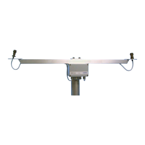
User's Guide ________________________________________________________ The WAT12 transmitter provides the sensors with a throughput for optional heating power. A thermostat switch is available as an option to automatically connect the heating power in temperatures below +4 °C. 0206-041 Figure 1 WAT12 Analog Wind Transmitter... -
Page 13: Chapter 3 Installation
Chapter 3 __________________________________________________ Installation CHAPTER 3 INSTALLATION This chapter provides you with information that is intended to help you install this product. Selecting Location Allow sufficient clearance for the wind sensors. Wind sensors should not be located next to a building or any other object that might affect the flow of air. -
Page 14: Figure 3 Recommended Mast Length On Top Of A Building
User's Guide ________________________________________________________ In general, any object of height (h) will not remarkably disturb wind measurement at a minimum distance of 10 There should be at least 150 m open area in all directions from the mast. Refer to Figure 2 on page 11. 0204-041 Figure 3 Recommended Mast Length on Top of a... -
Page 15: Installation Procedure
For installation, follow the procedure below and refer to corresponding sections for details. Remove the four screws holding the cover of the WAT12 transmitter. Remove the cover. Select the current output span, as well as direction and speed scaling according to the instructions in section Jumper Settings on page 14. -
Page 16: Jumper Settings
User's Guide ________________________________________________________ Jumper Settings The loop current can be selected with the on-board jumper plugs. Several output ranges, such as 0 to 20 mA, 4 to 20 mA, 0 to 10 mA, 2 to 10 mA, 0 to 5 mA, and 1 to 5 mA, are available as user configurable options, each with factory-adjusted zero and span levels. -
Page 17: Figure 5 Jumpers For The Setting: 4 ... 20 Ma, 0
360 degrees corresponding to one full turn, rather it allows to calculate the average direction during northerly winds. These settings are carried out by the jumpers of the WAT12 transmitter as described in Table 3 below. Table 3... -
Page 18: Connections
Jumpers for the Setting: 0 ... 10 mA, 0° ... 540°, 0 ... 51.2 m/s Connections The WAT12 transmitter provides the line cable entry through a gland for a cable with a diameter from 7 to 10 mm. For better protection against RF interference, bend the cable shield as illustrated in Figure 8 on page 17. -
Page 19: Figure 8 Cable Shield Bent Over The Plastic Sleeve And O-Ring
0206-046 Figure 8 Cable Shield Bent over the Plastic Sleeve and O-ring The WAT12 transmitter has three I/O connectors as listed in Table 4 on page 18. For the location of the connectors, refer to Figure 9 below. 0206-047 Figure 9 I/O Connectors The following numbers refer to Figure 9 above. -
Page 20: Sensor Wiring
The transmitter connects to the wind sensors with the cross- arm's standard cables through two cable glands. Through these cables the WAT12 transmitter both feeds the sensor power and receives the wind data. Plug-in type screw terminal connectors are provided both for the sensor cables and the output line cable. -
Page 21: Signal Output
Typically, only a 4-wire shielded cable is required for the line between the WAT12 transmitter and the receiving end. Two of the four wires provide the operating power for the system. The other two are for the current source outputs from the WAT12 transmitter;... -
Page 22: Figure 12 Wiring For High Noise Environment
User's Guide ________________________________________________________ Figure 12 below illustrates wiring for high noise environment. It is essential to ground the cable also at the power supply. 0206-050 Figure 12 Wiring for High Noise Environment Figure 13 below illustrates wiring for long distance with the 5 mA loop current. -
Page 23: Powering
Figure 14 Long Distance Wiring with Four Wires Powering The WAT12 transmitter accepts a wide range of input power, from 12 to 28 VDC. When the 5 mA loop current is selected, the total current consumption is less than 40 mA including the sensors and the loop current. -
Page 24: Optional Heating Power
I/O line. Optional Heating Power The WAT12 transmitter also provides the sensors with a throughput for optional heating power. The heating power connection requires an extra pair of wires. Since the heating... -
Page 25: Wiring Examples
Chapter 3 __________________________________________________ Installation Wiring Examples Refer to Figure 16 below for the basic wiring, when the WAA151 and WAV151 wind sensors are connected to the WAT12 transmitter. 0206-054 Figure 16 Basic Wiring with WAA151 and WAV151 Sensors Figure 17 on page 24 illustrates the wiring with WHP151 Mains Power Supply. -
Page 26: Figure 17 Wiring With Whp151 Mains Power Supply
User's Guide ________________________________________________________ 0206-055 Figure 17 Wiring with WHP151 Mains Power Supply 24 _____________________________________________________M210309EN-A... -
Page 27: Figure 18 Wiring With Whp25 Mains Power Supply And The 252 Series Wind Sensors
Chapter 3 __________________________________________________ Installation 0206-056 Figure 18 Wiring with WHP25 Mains Power Supply and the 252 Series Wind Sensors VAISALA__________________________________________________________25... -
Page 28: Mounting The Thermostat Switch
Figure 19 below. For standard wiring, refer to Figure 20 on page 27. 0206-057 Figure 19 Mounting the Thermostat Switch inside the WAT12 Junction Box The following numbers refer to Figure 19 above. 1 = Thermostat switch 2 = Regulator... -
Page 29: Mounting
Ø 60 mm pole mast, with the standard mounting clamp. The arrow on the cover of the junction box must point to north. 0206-059 Figure 21 Mounting WAT12 to the Top of a Pole Mast VAISALA__________________________________________________________27... -
Page 30: Mounting Wind Sensors To Wat12
Always ground the mast equipment case close to the mast with a short and low-resistance cable. Mounting Wind Sensors to WAT12 0110-005 Figure 22 Installation of the Wind Sensors WAA151 and WAV151 to WAT12... -
Page 31: Alignment
Verification If the signal cable from the WAT12 transmitter is connected to the data collection system and the system is powered up, check that the wind readings react correctly. For testing the anemometer, rotate the cups manually. - Page 32 User's Guide ________________________________________________________ This page intentionally left blank. 30 _____________________________________________________M210309EN-A...
-
Page 33: Chapter 4 Maintenance
Chapter 4 ________________________________________________ Maintenance CHAPTER 4 MAINTENANCE This chapter provides information that is needed in basic maintenance of WAT12 Analog Wind Transmitter. Periodic Maintenance Visual Checking Check every 1 to 2 years that the printed circuit board is not corrored. -
Page 34: Table 6 Jumper Selectable Reference Sources For Testing
000° / 008° / 357° Speed 0.0 m/s / 0.8 m/s / 51.2 m/s Follow the procedure below to test the WAT12 transmitter functionality with the reference signals: Remove the four screws holding the cover of the WAT12 transmitter. Remove the cover. -
Page 35: Replacing Consumables
ESD Protection on page 7. When replacing the thermostat switch, refer to section Mounting the Thermostat Switch on page 26. Parts List for Consumables Table 8 Available Spare Parts Spare Part Order Code Component Board for WAT12 16637WA Thermostat switch 16923WA VAISALA__________________________________________________________33... - Page 36 User's Guide ________________________________________________________ This page intentionally left blank. 34 _____________________________________________________M210309EN-A...
-
Page 37: Chapter 5 Troubleshooting
Chapter 5 ______________________________________________ Troubleshooting CHAPTER 5 TROUBLESHOOTING This chapter describes common problems, their probable causes and remedies, and provides contact information. Common Problems Table 9 Some Common Problems and their Remedies Problem Probable Cause Remedy Data is not received Improper or loose Check wiring and by the data connections... -
Page 38: Getting Help
User's Guide ________________________________________________________ Getting Help For technical questions or for comments on the manuals, contact the Vaisala technical support: E-mail helpdesk@vaisala.com Telephone +358 9 8949 2789 +358 9 8949 2790 36 _____________________________________________________M210309EN-A... -
Page 39: Return Instructions
Pack the faulty product using an ESD protection bag of good quality with proper cushioning material in a strong box of adequate size. Please include the Problem Report in the same box. Send the box to: Vaisala Oyj SSD Service Vanha Nurmijärventie 21 FIN-01670 Vantaa Finland... - Page 40 User's Guide ________________________________________________________ This page intentionally left blank. 38 _____________________________________________________M210309EN-A...
-
Page 41: Chapter 6 Technical Data
Chapter 6 _______________________________________________Technical Data CHAPTER 6 TECHNICAL DATA This chapter provides technical data of WAT12 Analog Wind Transmitter. Specifications Table 10 WAT12 Analog Wind Transmitter Specifications Property Description / Value Equipment type Digital-to-analog current loop converter for Vaisala wind sensors... -
Page 42: 0.1 M/S
User's Guide ________________________________________________________ Property Description / Value Signal cable 4 wires minimum (VIN+, VIN-, DOP, SOP) Max. loop resistance 1800 ohm for 5 mA loop (incl. cable and 900 ohm for 10 mA loop receiver's input 450 ohm for 20 mA loop resistance) Full scale options: for direction...