Vaisala HMD60U Operating Manual
Humidity transmitter
Hide thumbs
Also See for HMD60U:
- Operating manual (13 pages) ,
- User manual (18 pages) ,
- Operating manual (21 pages)
Advertisement
Quick Links
HMD60U/Y-M210276en-A
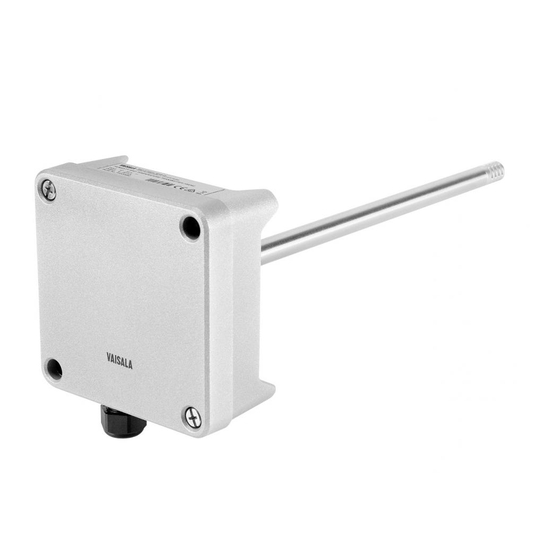
HUMIDITY TRANSMITTER HMD60U
HUMIDITY AND TEMPERATURE TRANSMITTER HMD60Y
MOUNTING
62 (2.44)
250 (9.84)
Ø 12
(0.47)
100 (3.94)
Mounting hole 82 (3.23)>>>
Figure 1 Dimensions of the HMD60U/Y
GROUNDING
flexible wires 0.5 mm²
(AWG 20), stranded wires
recommended
3
braid
brass
disks
25
rubber
ring
nut
D = Ø 7...10mm
cable
(If the cable diameter is less
than 7mm, use a shrinking
tube or an adhesive tape)
Figure 2 Signal cable grounding with
bushing 18941HM
2003-01-22
shielding tube
braid
brass disks
The
HMD60U/Y
temperature transmitters are two-wire
transmitters. They are duct mounted, and
the electronics can be disconnected
without dismantling the installation.
Mount the transmitter with two screws.
Place the drilling template on the duct
surface and drill the holes as indicated.
Remember to drill an additional hole for
calibration purposes. The calibration can
be conveniently performed on site with
the HMI41 or HM70 portable indicator
equipped with an appropriate probe and
optional calibration cable.
Open the lid and mount the cable
bushing set 18941HM. Do the grounding
according to Figure 2. W
the signal cable to the transmitter housing,
fold the cable braid between the brass disk
in order to achieve the best EMC per-
formance. Do not leave the bare shield of
the connected wires so that it can
shortcircuit the electronics!
HMD60U/Y
Operating Manual
humidity
and
hen connecting
1
Advertisement

Related Manuals for Vaisala HMD60U


Summary of Contents for Vaisala HMD60U
- Page 1 HMI41 or HM70 portable indicator equipped with an appropriate probe and optional calibration cable. Mounting hole 82 (3.23)>>> Figure 1 Dimensions of the HMD60U/Y GROUNDING flexible wires 0.5 mm² (AWG 20), stranded wires recommended Open the lid and mount the cable bushing set 18941HM.
-
Page 2: Electrical Connections
HMD60U/Y Operating Manual HMD60U/Y-M210276en-A ELECTRICAL CONNECTIONS T E S T Figure 3a. Electrical connections. R H G A IN T E S T R H O FF S E T T O F F S E T T G A IN Signal cables are connected to a removeable 5-pole screw connector. - Page 3 HMI41 or HM70 indicator equipped with attempt to clean the filter. appropriate probe optional calibration cable. adjustment needed, use the one-point calibration potentiometer. If you prefer to calibrate the HMD60U/Y transmitters against saturated salt solutions, use LiCl (11 %RH) and NaCl (75 %RH) solutions. 2003-01-22...
-
Page 4: Technical Data
-40...+80 °C Storage temperature range Housing: sensor head stainless steel Vaisala issues a guarantee for the material and electronics housing cast aluminium workmanship of this product under normal operating Cable lead-through: conditions for one year from the date of delivery.