
Related Manuals for Vaisala HUMICAP MMT330


Summary of Contents for Vaisala HUMICAP MMT330
- Page 1 USER'S GUIDE Vaisala HUMICAP® Moisture and Temperature Transmitter for Oil MMT330 M210733EN-F...
- Page 2 The contents are subject to change without prior notice. Please observe that this manual does not create any legally binding obligations for Vaisala towards the customer or end user. All legally binding commitments and agreements are included exclusively in the applicable supply contract or Conditions of...
-
Page 3: Table Of Contents
Pole Installation with Installation Kit for Pole or Pipeline ..30 Mounting Rain Shield with Installation Kit ......32 Panel Mounting Frame............32 Wiring ..................34 Cable Bushings ..............34 Grounding the Cables ............35 Grounding the Transmitter Housing........36 VAISALA ________________________________________________________________________ 1... - Page 4 User's Guide ______________________________________________________________________ Signal and Power Supply Wiring .........37 Connections to a 24 VAC Power Supply......39 MMT332 for High-Pressure Applications......40 MMT337 Small Pressure-Tight Probe .........40 MMT337 Probe with Swagelok Connector for Tight-place Installations............41 MMT338 for Pressurized Pipelines ........43 Tightening the Clasp Nut.............44 Ball Valve Installation Kit for MMT338.........45 Sampling Cell for MMT338..........48 Optional Modules ..............49...
- Page 5 Serial Output Settings............108 Using Display/Keypad ............108 Using Serial Line ............... 109 SERI................109 SMODE ................ 110 ADDR ................110 INTV ................111 SDELAY ............... 111 ECHO................111 Data Recording..............112 Selecting Data Recording Quantities ........ 112 VAISALA ________________________________________________________________________ 3...
- Page 6 User's Guide ______________________________________________________________________ DSEL ................112 View Recorded Data ............113 DIR ................113 PLAY ................114 Deleting the Recorded Files ..........115 UNDELETE ..............115 Analog Output Settings ............116 Changing Output Mode and Range........116 Analog Output Quantities ..........118 AMODE/ASEL ..............118 Analog Output Tests............119 ITEST ................120 Analog Output Fault Indication Setting......120 AERR................121 Operation of Relays..............121...
- Page 7 Temperature..............159 Operating Environment ............. 160 Probe Specifications ............160 MMT332 ............... 160 MMT337 ............... 160 MMT338 ............... 160 Inputs and Outputs............161 Mechanics ................. 161 Technical Specifications of Optional Modules ....162 Power Supply Module ..........162 VAISALA ________________________________________________________________________ 5...
- Page 8 User's Guide ______________________________________________________________________ Analog Output Module..........162 Relay Module ...............162 RS-485 Module ............163 LAN Interface Module...........163 WLAN Interface Module ..........163 Data Logger Module.............163 Options and Accessories ............164 Dimensions (mm/inch) ............165 MMT332 ................167 MMT337 ................167 MMT337 with Swagelok Connector........168 MMT338 ................168 APPENDIX A MODBUS REFERENCE ................169 Function Codes..............169 Register Map .................170...
- Page 9 Modifying an Alarm Limit ............78 Figure 47 Service Port Connector and User Port Terminal on Motherboard ................ 80 Figure 48 Connection Example between PC Serial Port and User Port .. 81 Figure 49 Network Interface Menu ............85 VAISALA ________________________________________________________________________ 7...
- Page 10 User's Guide ______________________________________________________________________ Figure 50 IP Configuration Menu..............85 Figure 51 Wireless LAN Settings..............88 Figure 52 Entering Network SSID.............88 Figure 53 Selecting the Wireless Network Type........88 Figure 54 Web Configuration Interface for LAN ........91 Figure 55 Opening a Serial Connection............92 Figure 56 Opening a Telnet Connection...........93 Figure 57 Device Information on Display..........104...
- Page 11 Configuration Parameter Registers........173 Table 36 Configuration Flag Registers..........173 Table 37 MMT330 Exception Status Outputs ........173 Table 38 MMT330 MODBUS Diagnostics..........174 Table 39 MMT330 MODBUS Device Identification ....... 175 Table 40 MMT330 MODBUS Exception Responses ......175 VAISALA ________________________________________________________________________ 9...
- Page 12 User's Guide ______________________________________________________________________ This page intentionally left blank. 10 __________________________________________________________________ M210733EN-F...
-
Page 13: General Information
This chapter provides general notes for the manual and the product. About This Manual This manual provides information for installing, operating, and maintaining Vaisala HUMICAP® Moisture and Temperature Transmitter for Oil MMT330. Contents of This Manual This manual consists of the following chapters: - Chapter 1, General Information, provides general notes for the manual and the product. -
Page 14: Version Information
User's Guide ______________________________________________________________________ Version Information Table 1 Manual Revisions Manual Code Description M210733EN-F May 2011. This manual. Applicable from transmitter software version 5.10 onward. Added MODBUS protocol. Updated serial line command descriptions. Updated storage temperature range. M210733EN-E Previous version. Added PuTTY terminal application instructions, revised description of the MI70 Link software. -
Page 15: Safety
Chapter 1 ________________________________________________________ General Information Safety The Vaisala HUMICAP® Moisture and Temperature Transmitter for Oil MMT330 delivered to you has been tested for safety and approved as shipped from the factory. Note the following precautions: Ground the product, and verify outdoor installation grounding WARNING periodically to minimize shock hazard. -
Page 16: Recycling
Dispose of batteries and the unit according to statutory regulations. Do not dispose of with regular household refuse. Regulatory Compliances EU Declaration of Conformity The Vaisala HUMICAP® Moisture and Temperature Transmitter for Oil MMT330 is in conformity with the provisions of the following EU directives: - Low Voltage Directive... -
Page 17: Dnv Type Approval
Chapter 1 ________________________________________________________ General Information DNV Type Approval The Vaisala HUMICAP® Moisture and Temperature Transmitter for Oil MMT330 is found to comply with Det Norske Veritas' Rules for Classification of Ships, High Speed & Light Craft and Det Norske Veritas' Offshore standards. -
Page 18: Transmitters With Wlan Interface
Cet appareil numérique de la classe [B] est conforme à la norme NMB- 003 du Canada. Patent Notice The Vaisala HUMICAP® Moisture and Temperature Transmitter for Oil MMT330 is protected by, for example, the following patents and their corresponding national rights: Finnish patent 98861, French patent 6650303, German patent 69418174, Japanese patent 3585973, UK patent 0665303, and U.S. -
Page 19: License Agreement
Chapter 1 ________________________________________________________ General Information License Agreement All rights to any software are held by Vaisala or third parties. The customer is allowed to use the software only to the extent that is provided by the applicable supply contract or Software License Agreement. - Page 20 User's Guide ______________________________________________________________________ This page intentionally left blank. 18 __________________________________________________________________ M210733EN-F...
-
Page 21: Chapter 2 Product Overview
Chapter 2 __________________________________________________________ Product Overview CHAPTER 2 PRODUCT OVERVIEW This chapter introduces the features, advantages, and the product nomenclature of the Vaisala HUMICAP® Moisture and Temperature Transmitter for Oil MMT330. Introduction to MMT330 The MMT330 transmitter is a microprocessor based instrument for the measurement of moisture in terms of water activity for example in the lubrication of circulation systems or in transformer oil. -
Page 22: Basic Features And Options
User's Guide ______________________________________________________________________ Table 3 Quantities Measured by MMT330 Quantity Abbreviation Metric Unit Non-Metric Unit Water activity Temperature ºC ºF Table 4 Optional Quantities Measured by MMT330 Quantity Abbreviation Metric Unit Non-Metric Unit ppm for transformer oil only Basic Features and Options - Several probes for various applications - User-friendly display - Different probe mounting kits and probe cable lengths... -
Page 23: Structure Of The Transmitter
Transmitter Body The numbers refer to Figure 1 above: Signal + powering cable gland Cable gland for optional module, or WLAN antenna connector Cable gland for optional module Cover screw (4 pcs) Display with keypad (optional) Cover LED VAISALA _______________________________________________________________________ 21... -
Page 24: Figure 2 Inside The Transmitter
User's Guide ______________________________________________________________________ 0604-006 Figure 2 Inside the Transmitter The following numbers refer to Figure 2 above: Service port (RS-232) DIP switches for analog output settings Power supply and signal wiring screw terminals Relay, data logger, RS-422/485, LAN, or WLAN module (optional) Grounding connector Power supply module (optional) -
Page 25: Probe Options
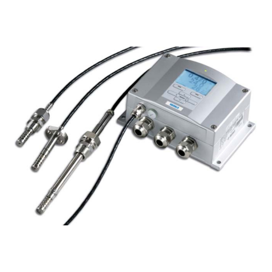
The following numbers refer to Figure 3 above: = MMT332 for high-pressure applications = MMT337 small pressure-tight probe = MMT338 adjustable probe for pressurized pipelines (40 bar, ball valve) Probe cable lengths are 2 m, 5 m, and 10 m. VAISALA _______________________________________________________________________ 23... -
Page 26: Typical Applications
User's Guide ______________________________________________________________________ Typical Applications Method Used for Measuring Moisture in Oil The MMT330 transmitter measures water in oil in terms of water activity (aw) which can be determined as follows: water activity indicates the amount of oil in the scale of 0 - 1 aw. In this scale, 0 aw is an indication of completely water free oil and 1 aw an indication of oil fully saturated with water. -
Page 27: Transformer Oil
Moisture level in oil is thus a true indicator of moisture present in the paper insulation. In addition, it must be noted that capacity of oil to absorb water depends both on the chemical structure of the oil and the additives. VAISALA _______________________________________________________________________ 25... -
Page 28: Figure 4 The Water Solubility Of Transformer Oils Versus Temperature
User's Guide ______________________________________________________________________ WATER SOLUBILITY IN MINERAL TRANSFORMER OIL 10000 1000 average water solubility range of variation due to oil type range of variation due to oil type Temperature (°C) 0510-029 Figure 4 The Water Solubility of Transformer Oils versus Temperature The margins show the range of variation of water solubility found in mineral oils. -
Page 29: Chapter 3 Installation
This chapter provides you with information that is intended to help you install the product. Mounting the Housing Standard Mounting Mount the housing by fastening the transmitter to the wall with 4 screws, for example, M6 (not provided). 0804-066 Figure 5 Standard Mounting Dimensions (in mm/inch) VAISALA _______________________________________________________________________ 27... -
Page 30: Wall Mounting With Wall Mounting Kit
User's Guide ______________________________________________________________________ Wall Mounting with Wall Mounting Kit When mounting with wall mounting kit the mounting plate (Vaisala order code 214829) can be installed directly on wall or onto a standard wall box (also US junction box). When wiring through back wall, remove the plastic plug from the wiring hole in the transmitter before mounting. -
Page 31: Mounting With Din Rail Installation Kit
Mounting with DIN Rail Installation Kit DIN rail installation kit includes a wall mounting kit, 2 clip-fasteners, and 2 screws M4 x 10 DIN 7985 (Vaisala order code: 215094). Attach two spring holders to the plastic mounting plate by using the screws provided in the installation kit. -
Page 32: Pole Installation With Installation Kit For Pole Or Pipeline
Pole Installation with Installation Kit for Pole or Pipeline Installation kit for pole or pipeline (Vaisala order code: 215108) includes the metal mounting plate and 4 mounting nuts for pole mounting. When mounting, the arrow in the metal mounting plate must point upward, see Figure 11 on page 31. -
Page 33: Figure 11 Mounting With Metal Wall Mounting Plate
Mount the plate to wall with 4 screws M8 (not provided) Fasten MMT330 to the mounting plate with 4 fixing screws M6 (provided) Note the position of the arrow when mounting. This side must be up when mounting. 0509-051 Figure 12 Dimensions of Metal Mounting Plate (mm/inch) VAISALA _______________________________________________________________________ 31... -
Page 34: Mounting Rain Shield With Installation Kit
Panel Mounting Frame To enable a neat and dirt free embedded installation of the transmitter, a panel mounting frame is available as an option (Vaisala order code: 216038). The frame is a thin, flexible plastic frame for the transmitter, with adhesive tape on one side. -
Page 35: Figure 14 Panel Mounting Frame
Chapter 3 _______________________________________________________________ Installation 0704-002 Figure 14 Panel Mounting Frame The following numbers refer to Figure 14 above: Panel (not included) Panel mounting frame 0804-083 Figure 15 Panel Mounting Dimensions (mm/inch) VAISALA _______________________________________________________________________ 33... -
Page 36: Wiring
User's Guide ______________________________________________________________________ Wiring Cable Bushings A single electrical cable with a screen and three to ten wires is recommended for power and analog/serial connections. The cable diameter should be 8 ... 11 mm. The number of cable bushings depends on the transmitter options. -
Page 37: Grounding The Cables
Chapter 3 _______________________________________________________________ Installation Grounding the Cables Ground the screen of the electrical cable properly to achieve the best possible EMC performance. 0504-049 Figure 17 Grounding the Screen of Electrical Cable VAISALA _______________________________________________________________________ 35... -
Page 38: Grounding The Transmitter Housing
User's Guide ______________________________________________________________________ Refer to Figure 17 on page 35 when performing the procedure below. Cut back outer sheath to desired length. Cut back screen braiding or screen foil to dimension X. Push the domed cap nut (item 1) and the seal insert with contact socket of the gland (item 2+3) onto the cable as shown in the diagram. -
Page 39: Signal And Power Supply Wiring
Screw Terminal Block on Motherboard The following numbers refer to Figure 18 above: Power supply terminals 10 ... 35 VDC, 24 VAC User port (RS-232 terminals) Analog signal terminals Make sure that you connect only de-energized wires. WARNING VAISALA _______________________________________________________________________ 37... - Page 40 User's Guide ______________________________________________________________________ Open the transmitter cover by taking out the four cover screws. Insert the power supply wires and signal wires through the cable bushing in the bottom of the transmitter; see the grounding instructions in the previous sections. Connect the analog output cables to terminals: Ch1 +, Ch1-, Ch2+, Ch2-.
-
Page 41: Connections To A 24 Vac Power Supply
To prevent fire and/or damage, if either 24 VAC wire is grounded or connected to a "-", "0", or "GND" terminal of any other device, you must connect the same wire on the "-" terminal also on this instrument. 0703-041 Figure 19 Connections to 24 VAC Power Supply VAISALA _______________________________________________________________________ 39... -
Page 42: Mmt332 For High-Pressure Applications
User's Guide ______________________________________________________________________ MMT332 for High-Pressure Applications The MMT332 probe is a small, pressure-tight probe equipped with an installation flange. It is suitable for high-pressure applications; up to 250 bar. 0510-030 Figure 20 MMT332 Installation The following numbers refer to Figure 20 above: Screw, 4 pcs, hexagon socket head (provided) O-ring (provided) Threaded sleeve (not provided) -
Page 43: Mmt337 Probe With Swagelok Connector For Tight-Place Installations
Chapter 3 _______________________________________________________________ Installation MMT337 Probe with Swagelok Connector for Tight-place Installations Swagelok installation kit for the MMT337 probe includes Swagelok connector with ISO3/8" thread ( Vaisala order code: SWG12ISO38) or NPT1/2" thread (Vaisala order code:SWG12NPT12). 0509-144 Figure 21 MMT337 Probe with Swagelok Installation Kit... - Page 44 User's Guide ______________________________________________________________________ Preparing installation. The connector options are the following: R3/8" ISO (Swagelok code SS-12M0-1-6RTBT) 1/2" NPT (Swagelok code SS-12M0-1-8BT) Note that the connector inner diameters extend for Ø12 mm probe. Probe position. Before the final tightening check that the upper edge of the connector nut is in line with the upper edge of the probe.
-
Page 45: Mmt338 For Pressurized Pipelines
The following two fitting body options are available: - Fitting Body ISO1/2 solid structure - Fitting Body NPT1/2 solid structure Table 5 MMT338 Probe Dimensions Probe type Probe Dimension Adjustment Range Standard 178 mm 120 mm Optional 400 mm 340 mm VAISALA _______________________________________________________________________ 43... -
Page 46: Tightening The Clasp Nut
User's Guide ______________________________________________________________________ 0507-025 Figure 24 Sealing of Fitting Body into Process Tightening the Clasp Nut Adjust the probe to a suitable depth according to the type of installation. Tighten the clasp nut first manually. Mark the fitting screw and the clasp nut. Tighten the nut a further 50 ... -
Page 47: Ball Valve Installation Kit For Mmt338
Ball Valve Installation Kit for MMT338 The ball valve installation kit (Vaisala order code: BALLVALVE-1) is preferred when connecting the probe to a pressurized process or pipeline. Use the ball valve set or a 1/2" ball valve assembly with a ball hole of ø14 mm or more. -
Page 48: Figure 26 Installing The Mmt338 Probe Through A Ball Valve Assembly
User's Guide ______________________________________________________________________ 0507-043 Figure 26 Installing the MMT338 Probe through a Ball Valve Assembly The following numbers refer to Figure 26: Manual press tool Handle of the ball valve Probe Process chamber or pipeline Groove on the probe indicates the upper adjustment limit Filter Ball of the ball valve Fitting screw... - Page 49 If you wish to remove the probe from the process, note that you have to pull the probe out far enough. You cannot close the valve if the groove on the probe body is not visible. VAISALA _______________________________________________________________________ 47...
-
Page 50: Sampling Cell For Mmt338
Then, a by-pass sampling line may be feasible. Sampling Cell with Swagelok Connectors (Vaisala order code: DMT242SC2) is available as an optional accessory. -
Page 51: Optional Modules
Connect AC (mains) voltage wires to these terminals Grounding terminal In case the module is not installed in the factory, connect wires from these terminals to the POWER 10 ... 35V 24V terminals in the screw terminal of the motherboard. VAISALA _______________________________________________________________________ 49... -
Page 52: Installation
User's Guide ______________________________________________________________________ Installation Disconnect the power and open the transmitter cover. Remove the protective plug from the cable gland and thread the wires. In case the power supply module is installed in the factory, continue with the step 5. To attach the module fasten the power module to the bottom of the housing with four screws. -
Page 53: Warnings
La conduttura elettrica può essere collegata al modulo di alimentazione elettrica soltanto da un elettricista autorizzato. Non staccare l’alimentazione elettrica dal trasmettitore quando è acceso. Non collegare la corrente elettrica al modulo di alimentazione elettrica se non è installato nel trasmettitore MMT330. Collegare sempre il morsetto protettivo a terra! VAISALA _______________________________________________________________________ 51... - Page 54 User's Guide ______________________________________________________________________ Dette produkt er i overensstemmelse med direktivet om lavspænding (2006/95/EØS). Netstrømskoblingen til må kun tilsluttes strømforsyningsmodulet af en autoriseret elinstallatør Strømforsyningsmodulet må ikke løsgøres fra senderen, mens spændingen er sluttet til. Slut ikke netspændingen til strømforsyningsmodulet, når det ikke er installeret i MMT330- senderen Forbind altid den beskyttende jordklemme! Dit product voldoet aan de eisen van de richtlijn 2006/95/EEG...
- Page 55 EEC). Připojení síťového napájení k napájecímu modulu smí provádět pouze oprávněný elektrikář. Neodpojujte napájecí modul od snímače při zapnutém napájení. Nepřipojujte síťové napájení k napájecímu modulu, pokud není instalován ve snímači MMT330. Vždy zapojte ochrannou zemnící svorku! VAISALA _______________________________________________________________________ 53...
-
Page 56: Galvanic Isolation For Output
User's Guide ______________________________________________________________________ Galvanic Isolation for Output If galvanic isolation of the power supply line from the output signals is needed, MMT330 can be ordered with optional output isolation module. This module prevents harmful grounding loops. Output isolation module is not needed when using the power supply NOTE module. -
Page 57: Installation And Wiring
Select the quantity and scale the channel via the serial line or display/keypad, see section Analog Output Quantities on page 118. For testing the analog output, see Section Analog Output Tests on page 119. For fault indication setting, see section Analog Output Fault Indication Setting on page 120. VAISALA _______________________________________________________________________ 55... -
Page 58: Relays
User's Guide ______________________________________________________________________ Relays MMT330 can be equipped with one or two configurable relay modules. Each module contains two configurable relays. See the contact ratings in section Technical Specifications of Optional Modules on page 162. Installation and Wiring Disconnect the power and open the transmitter cover. In case the relay-module is installed in the factory, continue with step 5. -
Page 59: Figure 32 Relay Module
Before opening the transmitter you must switch off both the transmitter and the voltage connected to the relay terminals. WARNING Do not connect the mains power to relay unit without grounding the transmitter. VAISALA _______________________________________________________________________ 57... -
Page 60: Rs-422/485 Interface
User's Guide ______________________________________________________________________ RS-422/485 Interface The RS-422/485 Interface enables communication between an RS-485 network and the MMT330 transmitter. The RS-485 interface is isolated and offers a maximum communications rate of 115 200 bits/s. (For maximum bus length of 1 km, use bit rate 19200 b/s or less.) When selecting an RS-232 to RS-485 converter for the network, avoid self-powered converters, as they do not necessarily support the needed power consumption. -
Page 61: Installation And Wiring
Use the bus type (4-wire/2-wire) to select the selection switch 3. In 4-wire mode RS-485 master sends data to the MMT330 through terminals Rx D1+ and Rx D0- and receives data from MMT330 through terminals Tx D1+ and Tx D0-. VAISALA _______________________________________________________________________ 59... -
Page 62: Figure 34 4-Wire Rs-485 Bus
User's Guide ______________________________________________________________________ Termination Termination 120R Rx D0- 120R Rx D1+ Shield Tx D0- Tx D1+ Stub RS485 bus master Junction box Twisted pair Address NN Switch Tx D0- Term off Tx D1+ Term off Shield 2/4 wire on Rx D0- RS422 off Rx D1+ Stub... -
Page 63: Figure 35 2-Wire Rs-485 Bus
2-Wire (Switch 3: Off) RS-485 master Data MMT330 ↔ ↔ When operating in communication mode RS-422, set both switches 3 and 4 to ON position (4-wire wiring is required for RS-422 mode). Connect the power and close the cover. VAISALA _______________________________________________________________________ 61... -
Page 64: Lan Interface
RS-232 User Port is disabled. The LAN interface module must be installed at the factory (when ordering the transmitter), or by a Vaisala Service Center. Once installed, the module is automatically used by the transmitter. The physical connection to the network is made to the RJ45 connector on the LAN interface module, using a standard twisted pair Ethernet cable (10/100Base-T). -
Page 65: Wlan Interface
DHCP server that provides the settings. The WLAN interface also provides a web configuration interface, which you can access by entering the IP address of the WLAN interface in the address field of a web browser. VAISALA _______________________________________________________________________ 63... -
Page 66: Attaching The Wlan Antenna
Attaching the WLAN Antenna The LAN interface module must be installed at the factory (when ordering the transmitter), or by a Vaisala Service Center. Before taking the transmitter into use, you must attach the antenna of the WLAN interface into the RP-SMA connector on the transmitter cover. The location of the antenna is shown in Figure 73 on page 166. -
Page 67: Data Logger Module
When browsing the stored data, the time offset is applied to the timestamps shown in the graphical history, and data outputted from the serial port. The timestamps in the data logger's memory remain as they were originally stored. VAISALA _______________________________________________________________________ 65... -
Page 68: Figure 38 Data Logger Module
The data logger module must be installed at the factory (when ordering the transmitter), or by a Vaisala Service Center. Once installed, the module is automatically used by the transmitter. When the module requires a new battery, the transmitter must be sent to Vaisala for maintenance. 66 __________________________________________________________________ M210733EN-F... -
Page 69: 8-Pin Connector
Signal GND (for both channels) Green Ch 2+ Yellow Ch 1 + Grey Supply - Supply - Supply - Pink Supply + Supply + Supply + Blue Data in RX Shield/Red Cable shield Cable shield Cable shield VAISALA _______________________________________________________________________ 67... - Page 70 User's Guide ______________________________________________________________________ This page intentionally left blank. 68 __________________________________________________________________ M210733EN-F...
-
Page 71: Chapter 4 Operation
18 seconds. When using the optional display and turning the transmitter on the first time, the language selection menu window opens. Select the language with ▼▲ arrow buttons and press the SELECT button (the left-hand button). VAISALA _______________________________________________________________________ 69... -
Page 72: Display/Keypad (Optional)
User's Guide ______________________________________________________________________ Display/Keypad (Optional) Basic Display Display shows you the measurement values of the selected quantities in the selected units. You can select 1 ... 3 quantities for the numerical basic display (see section Changing Quantities and Units on page 99.) 0706-046 Figure 40 Basic Display... -
Page 73: Graphic History
The cursor mode allows you to observe individual measuring points. The numerical value at the cursor position is shown at the left upper corner. The right upper corner shows the time from the present to the chosen moment (without the logger module), or the VAISALA _______________________________________________________________________ 71... -
Page 74: Figure 42 Graphical Display With Data Logger
User's Guide ______________________________________________________________________ date and time at the cursor position (when the logger module is installed). - If the optional data logger module is installed, you can scroll the cursor off the screen to move to a new point on the time axis. The new date will be displayed, and the cursor will be centered at the date where the cursor scrolled off the screen. -
Page 75: Menus And Navigation
Scroll to the System menu option, and press the ► button. The menu option is indicated with the wrench symbol. Scroll to the Language menu option, and the left-hand button. The menu option is indicated with the flag symbol. VAISALA _______________________________________________________________________ 73... -
Page 76: Rounding Setting
User's Guide ______________________________________________________________________ Select the language with the ▼▲ buttons, and confirm the selection by pressing the left-hand button. Press the right-hand button to exit to the basic display. Rounding Setting Round off one decimal by using the Rounding function . The default setting is rounding on. -
Page 77: Keypad Lock (Keyguard)
ADJ button once. Wait for a few seconds and the adjustment menu opens. Select Clear menu PIN, press CLEAR. NOTE You can also disable the keypad completely with serial command LOCK. See section Locking Menu/Keypad Using Serial Line on page 107. VAISALA _______________________________________________________________________ 75... -
Page 78: Factory Settings
User's Guide ______________________________________________________________________ Factory Settings Use the display/keypad to restore the factory settings. This operation does not affect the adjustments. Only settings available in the menus are restored. Press any of the arrow buttons to open the Main Menu. Select System by pressing the ► arrow button. Select Factory settings and press the REVERT button to confirm your selection. -
Page 79: Configuring A Display Alarm
Changes you do on the alarm editing page will take effect immediately, and may cause an alarm to appear on the screen. To select a quantity for the alarm, press the Change button and select the quantity from the list. VAISALA _______________________________________________________________________ 77... -
Page 80: Figure 46 Modifying An Alarm Limit
User's Guide ______________________________________________________________________ To modify or remove the alarm limit values, move the selection over the Act. above or Act. below field and press the Set button. You will be prompted to Modify or Remove the value. 0802-070 Figure 46 Modifying an Alarm Limit When modifying the value, use the arrow up and down buttons to change the value under the cursor. -
Page 81: Mi70 Link Program For Data Handling
Start using the program. There is usually no need to select a COM port manually, the MI70 Link software can detect it automatically. The MI70 Link program, and the optional connection cables, are available from Vaisala. See list of accessories in section Options and Accessories on page 164. VAISALA _______________________________________________________________________ 79... -
Page 82: Serial Line Communication
User's Guide ______________________________________________________________________ Serial Line Communication Connect the serial interface by using either the user port or the service port. For permanent interfacing to host system, use the user port.You can change the serial settings and operate in RUN, STOP, SEND, POLL, and MODBUS modes. -
Page 83: User Port Connection
- In POLL or MODBUS mode, the transmitter does not output anything after power-up. For a description of the modes, see section SMODE on page 110. RS-232 User Port cannot be used when a communication module NOTE (LAN, WLAN, or RS-422/485 Interface) has been installed. VAISALA _______________________________________________________________________ 81... -
Page 84: Service Port Connection
Link detects the USB connection automatically. There is no reason to uninstall the driver for normal use. However, if you wish to remove the driver files and all Vaisala USB cable devices, you can do so by uninstalling the entry for Vaisala USB Instrument Driver from the Add or Remove Programs (Programs and Features in Windows Vista) in the Windows Control Panel. -
Page 85: Using The Service Port
LAN and WLAN interfaces; refer to section List of Serial Commands on page 91. For instructions on how to connect using a terminal program, see section Terminal Program Settings on page 91. VAISALA _______________________________________________________________________ 83... -
Page 86: Ip Configuration
User's Guide ______________________________________________________________________ IP Configuration The IP settings of the LAN and WLAN interfaces are described in Table 15. The current settings can be viewed on the serial line or using the device information display; see section Device Information on page 104. Table 15 IP Settings for the LAN and WLAN Interfaces Parameter... -
Page 87: Using Display/Keypad
Move the cursor using the ◄► arrow buttons, and change the value under the cursor using the ▲▼ arrow buttons. Confirm the selection by pressing OK. After configuring the desired parameters, press EXIT to apply the changes and return to the basic display. VAISALA _______________________________________________________________________ 85... -
Page 88: Using Serial Line
User's Guide ______________________________________________________________________ Using Serial Line Use the serial line command NET to view or set the network settings for the LAN and WLAN interfaces. You can also refresh the network information or disconnect all active connections. NET [REFRESH] [DISCONNECT] [DHCP WEB] [DHCP IP SUBNET GATEWAY WEB]<cr>... -
Page 89: Wireless Lan Configuration
The security type of the wireless network. The options are: OPEN OPEN/WEP WPA-PSK/TKIP WPA-PSK/CCMP All other choices except OPEN require a security key; see below. Security key The encryption key or passphrase that is used with an encrypted network. VAISALA _______________________________________________________________________ 87... -
Page 90: Using Display/Keypad
User's Guide ______________________________________________________________________ Using Display/Keypad You can configure the Wireless LAN settings using the display/keypad as follows: Press any of the arrow buttons to open the Main Menu. Press the ► arrow button to select Interfaces. Press the ► arrow button to select Network settings. There will be a delay as the transmitter refreshes the network information. -
Page 91: Using Serial Line
Security type of the wireless network. The options are: OPEN OPEN/WEP WPA-PSK/TKIP WPA-PSK/CCMP Examples: >wlan ? Network SSID : WLAN-AP Type : OPEN > >wlan accesspoint wpa-psk/tkip Network SSID : accesspoint Type : WPA-PSK/TKIP WPA-PSK phrase ? thequickbrownfox Save changes (Y/N) ? y > VAISALA _______________________________________________________________________ 89... -
Page 92: Communication Protocol
When accessing the web configuration page, you must first log in. Username: user Password: vaisala The web configuration page provides similar network configuration options as the serial line and the display/keypad. It also has additional options for advanced users. For example, there are more options for securing the wireless network. -
Page 93: Terminal Program Settings
PuTTY terminal application for Windows. Perform the necessary cabling and configuration of the transmitter before following the instructions. PuTTY is available for download at www.vaisala.com. NOTE PuTTY cannot be used to access the transmitter through the User Port if the transmitter is configured to use the MODBUS protocol. -
Page 94: Opening A Serial/Usb Connection
COM port is selected in the Serial or USB line to connect to field. Change the port if necessary. If you are using a Vaisala USB cable, you can check the port that it uses by clicking the USB Finder... button. This opens the Vaisala USB Instrument Finder program that has been installed along with the USB drivers. -
Page 95: Opening A Telnet Session (Lan/Wlan)
Telnet session. If PuTTY is unable to connect the IP address you entered, it will show you an error message instead. If this happens, check the IP address and the connections, restart PuTTY, and try again. VAISALA _______________________________________________________________________ 93... -
Page 96: List Of Serial Commands
User's Guide ______________________________________________________________________ List of Serial Commands All commands can be issued either in uppercase or lowercase. In the command examples, the keyboard input by the user is in bold type. The notation <cr> refers to pressing the carriage return (Enter) key on your computer keyboard. -
Page 97: Table 19 Data Recording Commands
HELP List the currently available commands LIGHT Set the display backlight mode LOCK Lock the menu or disable the keypad MODBUS View MODBUS diagnostic counters Set oil-specific parameters for ppm conversion VERS Display the software version information VAISALA _______________________________________________________________________ 95... -
Page 98: Getting Measurement Message From Serial Line
User's Guide ______________________________________________________________________ Getting Measurement Message from Serial Line Starting Continuous Outputting Enter the R command to start the continuous output of measurements. R<cr> Example: >r 0.261 T= 23.8 'C H2O= 15 ppm > If a value is too long to fit to the allocated space in the output, or if there is an error in outputting the quantity, the value is displayed with stars ‘*’. -
Page 99: Assign An Alias For The Send Command
Address of the transmitter (0 ... 99) CLOSE The CLOSE command switches the transmitter back to the POLL mode. Example: >open 2 (opens the line to transmitter 2, other transmitters stay in POLL mode) >? (for example, display device information) >close (line closed) VAISALA _______________________________________________________________________ 97... -
Page 100: Formatting Serial Line Message
User's Guide ______________________________________________________________________ Formatting Serial Line Message NOTE Instead of using the FTIME and FDATE commands described in this section, you can use the FORM command with modifiers TIME and DATE. See section FORM on page 100. FTIME and FDATE FTIME and FDATE commands will enable/disable output of time and date to the serial line. -
Page 101: General Settings
CHANGE. The unit changes from metric to non-metric or the other way round. Press EXIT to return to the basic display. Changing the display quantities/units (by using the display/keypad) has NOTE no effect on the serial output data. VAISALA _______________________________________________________________________ 99... -
Page 102: Using Serial Line
User's Guide ______________________________________________________________________ Using Serial Line FORM Use the serial line command FORM to change the format or select a certain quantities for the output commands SEND and R. FORM [x]<cr> where Formatter string If no formatter string is entered, the command will display the currently active formatter string. -
Page 103: Unit
This command changes both the serial output and display units to either NOTE metric or non-metric units. When you want to output both metric and non-metric units simultaneously on the serial line and display, select the display units later by using the display/keypad. VAISALA ______________________________________________________________________ 101... -
Page 104: Date And Time
User's Guide ______________________________________________________________________ Date and Time Using Display/Keypad If the optional Data Logger Module is installed, you can change the time and date using the display/keypad. Press any of the arrow buttons to open the Main Menu. Select System and press the ►arrow button to confirm your selection. -
Page 105: Data Filtering
Select Off/Standard/Extended and press SELECT to confirm your selection. Press EXIT to return to the basic display. FILT Use the serial line command FILT [xxx] to set the filtering level. FILT [xxx]<cr> where OFF, ON, or EXT (default = OFF) VAISALA ______________________________________________________________________ 103... -
Page 106: Device Information
User's Guide ______________________________________________________________________ Device Information Use the display/keypad or the serial line to display the device information. Press the INFO button in the basic display to see the following information: - Present or past unacknowledged errors, if any - Device information - Current date and time (only shown if data logger module installed) - Adjustment information fed by the user - Measuring settings... -
Page 107: Light
>? MMT330 / 2.04 Serial number : A3420002 Batch number : A3210034 Adjust. date : 2005-08-07 Adjust. info : Pre-adjustment Vaisala/HEL Date : 2000-01-01 Time : 02:32:27 Serial mode : STOP Baud P D S : 4800 E 7 1... -
Page 108: Help
User's Guide ______________________________________________________________________ HELP Use the HELP command to list the commands. The available commands are determined by the device configuration and installed options. Example: >help ACAL ADDR AERR ALSEL ASEL CDATE CLOSE CTEXT DATE DELETE DSEL DSEND ECHO ERRS FCRH FILT FORM... -
Page 109: Resetting Transmitter By Using Serial Line
2 - Keypad completely disabled yyyy = 4-digit PIN code. The code can only be set when keypad locking level is 1. Examples: >lock 1 4444 Keyboard lock : 1 [4444] > >lock 1 Keyboard lock > VAISALA ______________________________________________________________________ 107... -
Page 110: Serial Output Settings
User's Guide ______________________________________________________________________ Serial Output Settings The communication settings for the user port can be changed via the serial line or by using the optional display/keypad. The communication settings for the service port are fixed and not changeable. NOTE If a communication module (LAN, WLAN, or RS-422/RS-485 Interface) has been installed, the user port is not accessible. -
Page 111: Using Serial Line
The settings can be changed one parameter at a time or all parameters at once. Example (changing all parameters): >seri 600 N 8 1 600 N 8 1 > Example (changing parity only): >seri O 4800 O 7 1 VAISALA ______________________________________________________________________ 109... -
Page 112: Smode
User's Guide ______________________________________________________________________ SMODE Use the SMODE command to set the user port start-up operating mode. SMODE [xxxx]<cr> where xxx = STOP, SEND, RUN, POLL, or MODBUS. Table 26 Selection of Output Modes Mode Measurement Output Available Commands STOP Only with the SEND command. All (default mode). SEND One measurement message All. -
Page 113: Intv
: 0 ? 10 >sdelay Serial delay : 10 ? ECHO Use the ECHO command to set the user port echo. The command either enables or disables echo of characters received. ECHO [x]<cr> where ON (enabled, default) or OFF (disabled) VAISALA ______________________________________________________________________ 111... -
Page 114: Data Recording
User's Guide ______________________________________________________________________ NOTE When using the RS-485 Interface with a 2-wire connection, always disable echo. When using a RS-232, RS-422/485 4-wire connection, LAN, or WLAN, you can enable or disable it as you wish. Data Recording Data recording function is always on and collects data automatically into the memory of the device. -
Page 115: View Recorded Data
(12 min intervals) 2007-05-29 05:48:00 194400 18 H2O (2 h intervals) 2007-05-19 02:00:00 19440 19 H2O (12 h intervals) 2007-03-23 12:00:00 3240 20 H2O (3 d intervals) 2006-04-20 00:00:00 21 H2O (12 d intervals) 2002-12-16 00:00:00 > VAISALA ______________________________________________________________________ 113... -
Page 116: Play
User's Guide ______________________________________________________________________ Example (without data logger module): >dir File description Oldest data available No. of points (10 s intervals) 2008-04-11 23:41:10 (90 s intervals) 2008-04-11 20:41:11 (12 min intervals) 2008-04-10 21:03:41 (2 h intervals) 2008-03-31 18:03:41 (12 h intervals) 2008-02-04 12:03:41 (3 d intervals) 2007-03-04 00:03:41... -
Page 117: Deleting The Recorded Files
UNDELETE Similarly to the DELETE command, the UNDELETE command is used without any arguments. It will recover all deleted data that has not been overwritten yet. VAISALA ______________________________________________________________________ 115... -
Page 118: Analog Output Settings
User's Guide ______________________________________________________________________ Analog Output Settings The analog outputs are set in the factory according to the order form. In case you want to change the settings, follow these instructions. See section Third Analog Output on page 54. Changing Output Mode and Range Both output channels have their own DIP switch module with 8 switches, see the position in Figure 2 on page 22 (DIP switches for analog output settings). - Page 119 █ █ █ If you have customized the error output setting (AERR), check that the NOTE set error values are still valid after changing the output mode/range. See section Analog Output Fault Indication Setting on page 120. VAISALA ______________________________________________________________________ 117...
-
Page 120: Analog Output Quantities
User's Guide ______________________________________________________________________ Analog Output Quantities Use the display/keypad to change and scale the analog output quantities. Press any of the arrow buttons to open the Main Menu. Select Interfaces by pressing the ► arrow button. Select Analog outputs by pressing the ► arrow button. Select Output 1/2/3 by pressing the ►... -
Page 121: Analog Output Tests
Select one of the testing options Force 0%/50%/100% of scale. Press TEST to confirm your selection. All outputs are tested simultaneously. The actual output value depends on the selected range. Press OK to stop testing. Press EXIT to return to the basic display. VAISALA ______________________________________________________________________ 119... -
Page 122: Itest
User's Guide ______________________________________________________________________ ITEST Use the serial line to test the operation of the analog outputs. Use the ITEST command to force the analog outputs to entered values. The set values remain valid until you enter the command ITEST without parameters or RESET the transmitter. -
Page 123: Aerr
"below" value, the relay is passive when the measured value is not between the setpoints. You can also set only one setpoint. See Figure 59 on page 122 for illustrative examples of the different measurement-based relay output modes. VAISALA ______________________________________________________________________ 121... -
Page 124: Figure 59 Measurement-Based Relay Output Modes
User's Guide ______________________________________________________________________ 1102-007 Figure 59 Measurement-Based Relay Output Modes 122 _________________________________________________________________ M210733EN-F... -
Page 125: Hysteresis
Live measurement (data available): relay active (C and NO outputs are closed) No live data (for example: error state, chemical purge or adjustment mode): relay released (C and NC outputs are closed) See Figure 60 on page 124 for illustrative examples of the FAULT/ONLINE STATUSrelay output modes. VAISALA ______________________________________________________________________ 123... -
Page 126: Figure 60 Fault/Online Status Relay Output Modes
User's Guide ______________________________________________________________________ 1102-040 Figure 60 FAULT/ONLINE STATUS Relay Output Modes FAULT/ONLINE STATUS relays are usually used in conjunction with an analog output to obtain validity information for the output value. NOTE If transmitter loses its power, all status-based relays are released similarly to the case of an instrument failure. -
Page 127: Enabling/Disabling Relays
When you have two relay modules, the relays of the module connected to slot MODULE 1 are called “relay 1” and “relay 2” and relays connected to slot MODULE 2 are called “relay 3” and “relay 4”. VAISALA ______________________________________________________________________ 125... -
Page 128: Rsel
User's Guide ______________________________________________________________________ 0509-142 Figure 61 Relay Indicators on Display The following number refers to Figure 61 above: Lists enabled relays. Activation state shown in black. Disabled relays are not shown. Use the display/keypad to set the relay outputs. Press any of the arrow buttons to open the Main Menu. Select Interfaces, confirm by pressing the ►arrow button. - Page 129 ON ? Rel3 ONLI above: - Rel3 ONLI below: - Rel3 ONLI hyst : - Rel3 ONLI enabl: ON ? Rel4 FAUL above: - Rel4 FAUL below: - Rel4 FAUL hyst : - Rel4 FAUL enabl: ON ? VAISALA ______________________________________________________________________ 127...
-
Page 130: Testing Operation Of Relays
User's Guide ______________________________________________________________________ Example of using relay 1 as fault alarm: Selecting relay 1 to follow the fault status and relay 2 to follow the temperature measurement. >rsel fault t Rel1 FAUL above: - Rel1 FAUL below: - Rel1 FAUL hyst : - Rel1 FAUL enabl: ON ? Rel2 T above: 0.00 'C ? 30... -
Page 131: Chapter 5 Modbus
Design the system so that only one MODBUS TCP client accesses the transmitter. - MODBUS TCP can process reliably only one MODBUS transaction at a time. Reduce the polling rate of the client to avoid nested transactions. VAISALA ______________________________________________________________________ 129... -
Page 132: Taking Modbus Into Use
(optional) or a PC connected to the serial line. For example, you can connect to the service port using the USB service cable (Vaisala order code: 219685). The transmitter must be powered from a suitable power supply during configuration. -
Page 133: Enabling Serial Modbus
Connect the USB service cable between a computer and the service port of the transmitter. Start the Vaisala USB Instrument Finder program (which has been installed on the computer along with the USB service cable driver), and check the COM port that the cable is using. - Page 134 User's Guide ______________________________________________________________________ Open a terminal program, and connect to the service port. The fixed settings serial line settings of the service port are 19200, 8, 1, N. Use the SMODE command to enable the MODBUS mode: > smode modbus Serial mode : MODBUS >...
-
Page 135: Enabling Ethernet Modbus
Press the EXIT button to save the changes. Note that the device address setting is not relevant for MODBUS TCP. In the MODBUS mode, the transmitter will respond to all valid MODBUS messages with any “unit identifier” value. VAISALA ______________________________________________________________________ 133... -
Page 136: Using Serial Line
Connect the USB service cable between a computer and the service port of the transmitter. Start the Vaisala USB Instrument Finder program (which has been installed on the computer along with the USB service cable driver), and check the COM port that the cable is using. - Page 137 For a description of the available settings, see section Wireless LAN Configuration on page 87. The MODBUS configuration is now complete. Reset or power cycle the transmitter to enable the MODBUS mode, and proceed with the installation of the transmitter. VAISALA ______________________________________________________________________ 135...
-
Page 138: Diagnostic Modbus Counters
User's Guide ______________________________________________________________________ Diagnostic MODBUS Counters MMT330 has diagnostic counters that can be used to pinpoint MODBUS problems. The counters are always active when the MODBUS protocol is enabled. Viewing Counters Using Display/Keypad You can use the display/keypad option to view and clear the counters. Enter the Main Menu and navigate to System ►... -
Page 139: Disabling Modbus
Alternatively, you can enter the Main Menu using the display/keypad option, and change the mode from the Interfaces submenu. The other communication settings of the output interface (User Port, LAN interface, or WLAN interface) will remain as configured, but the MODBUS protocol will be disabled. VAISALA ______________________________________________________________________ 137... - Page 140 User's Guide ______________________________________________________________________ This page intentionally left blank. 138 _________________________________________________________________ M210733EN-F...
-
Page 141: Chapter 6 Ppm Conversion
Traditionally, moisture in transformer oil is measured by using ppm units. The ppm output shows the average mass concentration of water in oil. Vaisala has this conversion readily available for mineral transformer oils. The moisture and temperature transmitter MMT330 has an option for ppm-output provided that this has been notified as placing the order of the transmitter.Vaisala has this conversion readily available for mineral... -
Page 142: Conversion Model With Oil-Specific Coefficients
Conversion Model with Oil-specific Coefficients For additional accuracy, oil-specific conversion model can be used both for mineral and silicon based oils. An oil sample has to be sent to Vaisala for modelling. As a result, the specific coefficients (A and B, see formula 1) for the transformer oil are determined by Vaisala. -
Page 143: Using Display/Keypad
- a temperature test chamber - for example, a conical flask (1L) sealed by PTFE stopper with an inlet for a moisture probe - MMT330 by Vaisala - magnetic stirrer. Procedure: Define the water content of the oil sample with the titration. Use the oil moisture level that is close to real conditions in the process. - Page 144 User's Guide ______________________________________________________________________ NOTE If the oil sample is very dry and the temperatures are close to each other, it may cause inaccuracy to the calculation model. In order to get the best possible performance it is recommended to use oil conditions that represent real conditions in application.
-
Page 145: Chapter 7 Maintenance
Install a new filter on the probe. When using the stainless steel filter, take care to tighten it properly (recommended force 5 Nm). New filters can be ordered from Vaisala, see section Options and Accessories on page 164. VAISALA ______________________________________________________________________ 143... -
Page 146: Changing The Sensor
User's Guide ______________________________________________________________________ Changing the Sensor The user can change HUMICAP® 180L2 sensors. Changing the sensor should be considered corrective maintenance, and it is not necessary in normal operation. If the accuracy of the transmitter does not seem to be within specification, it is more likely that the transmitter is in need of calibration and adjustment, and not sensor replacement. -
Page 147: Error States
Press the INFO button to display the error message. You can also check the error message via the serial interface by using the command ERRS . In case of constant error, please contact Vaisala; see section Technical Support on page 147. VAISALA ______________________________________________________________________ 145... -
Page 148: Table 29 Error Messages
Internal ADC read error Internal transmitter failure. Remove the transmitter and return the faulty unit to Vaisala Service. Checksum error in the internal Internal transmitter failure. Remove the configuration memory transmitter and return the faulty unit to Vaisala Service. -
Page 149: Technical Support
Chapter 7 ______________________________________________________________ Maintenance Technical Support For technical questions, contact the Vaisala technical support by e-mail at helpdesk@vaisala.com. Provide at least the following supporting information: - Name and model of the product in question - Serial number of the product... - Page 150 User's Guide ______________________________________________________________________ This page intentionally left blank. 148 _________________________________________________________________ M210733EN-F...
-
Page 151: Calibration And Adjustment
3 years. It is recommended that calibration is done always when there is a reason to believe that the device is not within the accuracy specifications. The user can calibrate the MMT330 or send it to Vaisala for calibration. For contact information of Vaisala Service Centers, see www.vaisala.com/services/servicecenters.html. -
Page 152: Cleaning The Sensor
User's Guide ______________________________________________________________________ Cleaning the Sensor Clean the sensor before storing the MMT338 probe and before calibration. For cleaning of the probe you need instrument air and heptane liquid. Dry with instrument air to prevent oxidation of the oil on the sensor. -
Page 153: Relative Humidity Adjustment
The indicator LED starts flashing. Insert the probe into a measurement hole of the 75 %RH (NaCl) reference chamber of the humidity calibrator HMK15. Use the adapter fitting for the MMT332, MMT337 and MMT338 probes. VAISALA ______________________________________________________________________ 151... -
Page 154: Using Display/Keypad
User's Guide ______________________________________________________________________ Wait at least 30 minutes for the sensor to stabilize (the indicator LED is lit continuously). Adjustment cannot be done if the conditions are not stabilized (indicator LED is flashing). Press the button NaCl 75 % to adjust the 75 %RH condition. After adjustment transmitter returns to normal operation mode (indicator LED is unlit). -
Page 155: Using Serial Line
When stabilized, type the high end reference value after the question mark and press ENTER . >crh 11.25 Ref1 ? c 11.24 Ref1 ? c 11.24 Ref1 ? 11.3 Press any key when ready ... 75.45 Ref2 ? c VAISALA ______________________________________________________________________ 153... -
Page 156: Relative Humidity Adjustment After Sensor Change
User's Guide ______________________________________________________________________ 75.57 Ref2 ? c 75.55 Ref2 ? c 75.59 Ref2 ? 75.5 > indicates that the adjustment has succeeded and the new calibration coefficients are calculated and stored.Enter the adjustment information (date and text) to the memory of the transmitter, see the commands CTEXT and CDATE . -
Page 157: Temperature Adjustment
ENTER only twice and insert the probe to the second reference. When the reading is stabilized, give the second reference temperature after the question mark and press ENTER . Please, note that the difference between the two temperature references must be at least 30 ºC. VAISALA ______________________________________________________________________ 155... - Page 158 User's Guide ______________________________________________________________________ Example (one-point adjustment): >ct 16.06 Ref1 ? c 16.06 Ref1 ? c 16.06 Ref1 ? c 16.06 Ref1 ? c 16.06 Ref1 ? c 16.06 Ref1 ? 16.0 Press any key when ready ... 16.06 Ref2 ? >...
-
Page 159: Analog Output Adjustment
Using Serial Line Enter the ACAL command and type the multimeter reading for each case. Continue by pressing ENTER . ACAL Example (current outputs): >acal (mA) ? 2.046 (mA) ? 18.087 (mA) ? 2.036 (mA) ? 18.071 > VAISALA ______________________________________________________________________ 157... -
Page 160: Feeding Adjustment Information
User's Guide ______________________________________________________________________ Feeding Adjustment Information This information is shown on the device information fields (see section Device Information on page 104.) Using Display/Keypad If you are not in the adjustment menu, press the ADJ button on the motherboard (opens the ADJUSTMENT MENU ). Select ►... -
Page 161: Chapter 9 Technical Data
Measurement range MMT342 -40 ... +180 °C (-40 ... +356 °F) MMT347 -40 ... +180 °C (-40 ... +356 °F) MMT348 -40 ... +180 °C (-40 ... +356 °F) Accuracy at +20 °C (+68 °F) ± 0.2 °C VAISALA ______________________________________________________________________ 159... -
Page 162: Operating Environment
User's Guide ______________________________________________________________________ Operating Environment Operating temperature for probes same as measurement ranges for transmitter body -40 ... +60 °C (40 ... +140°F) with display 0 ... +60 °C (+32 ... +140°F) Storage temperature without display -55 … +80 °C (-67 … +176 °F) with display -40 …... -
Page 163: Inputs And Outputs
(female) with screw terminals Probe cable diameter 5.5 mm Probe cable lengths 2 m, 5 m or 10 m Probe tube material AISI 316L Housing material G-AlSi 10 Mg (DIN 1725) Housing classification IP 65 (NEMA 4) VAISALA ______________________________________________________________________ 161... -
Page 164: Technical Specifications Of Optional Modules
User's Guide ______________________________________________________________________ Technical Specifications of Optional Modules Power Supply Module Operating voltage 100 ... 240 VAC 50/60 Hz Connections screw terminals for 0.5 ... 2.5 wire (AWG 20...14) Bushing for 8...11 mm diameter cable Operating temperature -40 ... +60 °C (-40 ... +140 °F) Storage temperature -40 ... -
Page 165: Rs-485 Module
13.7 million points / parameter Accuracy of the clock better than ±2 min/year Battery lifetime at -40 ... +30 ºC (-40 ... +86 ºF) 7 years at +30 ... +60 ºC (+86 ... +140 ºF) 5 years VAISALA ______________________________________________________________________ 163... -
Page 166: Options And Accessories
User's Guide ______________________________________________________________________ Options and Accessories Description Order Code MODULES Relay module RELAY-1 Analog Output Module AOUT-1 Isolated RS485 Module RS485-1 Power Supply Module POWER-1 Galvanic Isolation Module DCDC-1 SENSORS HUMICAP® 180L2 HUMICAP180L2 PT100 Sensor 10429SP FILTERS Stainless Steel Filter HM47453SP TRANSMITTER MOUNTING ACCESSORIES Wall Mounting Kit... -
Page 167: Dimensions (Mm/Inch)
Chapter 9 ____________________________________________________________ Technical Data Dimensions (mm/inch) 0506-035 Figure 72 Transmitter Body Dimensions VAISALA ______________________________________________________________________ 165... -
Page 168: Figure 73 Wlan Antenna Dimensions
User's Guide ______________________________________________________________________ 0804-035 Figure 73 WLAN Antenna Dimensions 166 _________________________________________________________________ M210733EN-F... -
Page 169: Mmt332
Chapter 9 ____________________________________________________________ Technical Data MMT332 0509-149 Figure 74 MMT332 Probe Dimensions MMT337 0509-146 Figure 75 MMT337 Probe Dimensions VAISALA ______________________________________________________________________ 167... -
Page 170: Mmt337 With Swagelok Connector
User's Guide ______________________________________________________________________ MMT337 with Swagelok Connector 0509-148 Figure 76 MMT337 Probe with (Optional) Swagelok Connector, Dimensions MMT338 0509-145 Figure 77 MMT338 Probe with Stainless Steel Filter (Oil Filter), Dimensions 168 _________________________________________________________________ M210733EN-F... -
Page 171: Appendix Amodbus Reference
2 commands are also supported giving better compatibility and allowing more efficient communication when needed. MODBUS diagnostic and device identification data can be read out only with the function codes dedicated for those purposes (08 and 43 / 14). VAISALA ______________________________________________________________________ 169... -
Page 172: Register Map
User's Guide ______________________________________________________________________ Register Map All data available via the MODBUS interface is grouped in six contiguous blocks of registers as described in Table 32 below. Table 32 MMT330 MODBUS Register Blocks Address Data Format Description 0001…0068 32-bit IEEE float Measurement data (read-only) 0257…0290 16-bit signed integer... -
Page 173: 16-Bit Integer Format
16-bit register values. When writing 16-bit values in configuration registers, they are always processed as signed integers in the range of -32768…+32767. You shall use the floating point registers to write values outside this 16-bit signed VAISALA ______________________________________________________________________ 171... -
Page 174: Measurement Data (Read-Only)
User's Guide ______________________________________________________________________ integer range. Maximum writable value is 32767 also for configuration registers that do not accept negative values. Measurement Data (Read-Only) Table 33 Measurement Data Registers Name Float Integer Unit 0003…0004 0258 (×0.01) °C 0029…0030 0271 (×0.0001) 0035…0036 0274 (×1) Available measurements depend on the instrument configuration. -
Page 175: Configuration Registers
Exception status outputs (read with function code 07) tell the summary of the MMT330 transmitter status as described in Table 37 below. Table 37 MMT330 Exception Status Outputs Output Name Description 0 (0x01) Fault status 1 = No errors 1 (0x02) Online status 1 = Online data available VAISALA ______________________________________________________________________ 173... -
Page 176: Diagnostic Sub-Functions
User's Guide ______________________________________________________________________ Status information is available also with register access; see section Status Registers (Read-Only) on page 172. Diagnostic Sub-Functions MMT330 supports some of the MODBUS diagnostic functions described in the MODBUS Application Protocol Specification V1.1b. These diagnostic functions are accessed with function code 08. See Table 38 below for details. -
Page 177: Device Identification Objects
“Unavailable” value (a quiet NaN for floating point data or zero for integer data) is returned instead. An exception is generated only for any access outside the register blocks defined in section Register Map on page 170. VAISALA ______________________________________________________________________ 175... - Page 178 User's Guide ______________________________________________________________________ 176 _________________________________________________________________ M210733EN-F...
- Page 180 *M210733EN*...