
Related Manuals for Vaisala DPT146


Summary of Contents for Vaisala DPT146
- Page 1 USER'S GUIDE Vaisala Dewpoint and Pressure Transmitter DPT146 for Compressed Air M211372EN-B...
- Page 2 The contents are subject to change without prior notice. Please observe that this manual does not create any legally binding obligations for Vaisala towards the customer or end user. All legally binding commitments and agreements are included exclusively in the applicable supply contract or Conditions of...
-
Page 3: Table Of Contents
DRYCAP® Technology ............20 Auto-Calibration ............. 20 Sensor Purge ..............20 Sensor Warming in High Humidities ......21 BAROCAP® Technology ............ 21 DPT146 Startup Sequence ............ 22 CHAPTER 4 INSTALLATION.................... 23 Transmitter Configuration Before Installation ....23 Selecting the Location ............24 Installing the Transmitter ............ - Page 4 USER'S GUIDE____________________________________________________________________ Sampling from a Process ............27 Sampling Accessories ............27 DMT242SC Sampling Cell ..........27 DMT242SC2 Sampling Cell with Swagelok Connectors..27 DSC74 Sampling Cell with Quick Connector and Leak Screw................28 DSC74B Two-Pressure Sampling Cell........29 DSC74C Two-Pressure Sampling Cell with Coil....31 DM240FA Duct Installation Flange........33 CHAPTER 5 OPERATION....................35 Transmitter Start-Up...............35...
- Page 5 Solving Typical Problems ............. 61 Error Messages ..............62 Unknown Serial Settings ............62 Technical Support ..............63 Product Returns ..............63 CHAPTER 8 TECHNICAL DATA ..................65 Specifications ................. 65 Spare Parts and Accessories..........68 Dimensions in mm ..............69 VAISALA ________________________________________________________________________ 5...
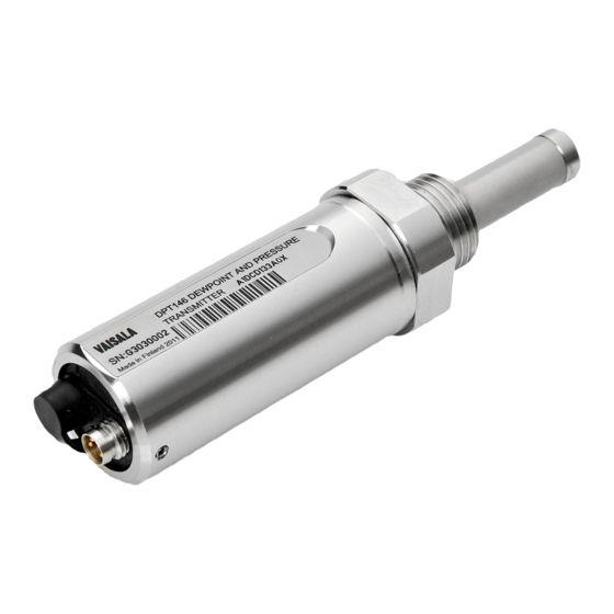
- Page 6 USER'S GUIDE____________________________________________________________________ List of Figures Figure 1 DPT146 with ISO G1/2” Thread ..........14 Figure 2 DPT146 Transmitter Structure..........15 Figure 3 Cable with Threaded Connector..........16 Figure 4 USB Service Cable..............16 Figure 5 Nokeval 301 Loop-Powered Display ........17 Figure 6 MPS1 Sensor................19 Figure 7 DPT146 Startup Sequence............22...
-
Page 7: Chapter 1 General Information
- Chapter 6, Maintenance, provides information that is needed in basic maintenance of the DPT146. - Chapter 7, Troubleshooting, describes common problems, their probable causes and remedies, and provides contact information for technical support. - Chapter 8, Technical Data, provides the technical data of the DPT146. VAISALA ________________________________________________________________________ 7... -
Page 8: Version Information
Related Manuals Table 2 Related Manuals Manual Code Manual Name M211370EN DPT146 Quick Guide Documentation Conventions Throughout the manual, important safety considerations are highlighted as follows: WARNING Warning alerts you to a serious hazard. If you do not read and follow instructions very carefully at this point, there is a risk of injury or even death. -
Page 9: Safety
Chapter 1 ________________________________________________________ General Information Safety The DPT146 delivered to you has been tested for safety and approved as shipped from the factory. Note the following precautions: Ground the product and verify outdoor installation grounding WARNING periodically to minimize shock hazard. -
Page 10: Recycling
Dispose of the unit according to statutory regulations. Do not dispose of with regular household refuse. Regulatory Compliances The Vaisala Dewpoint and Pressure Transmitter DPT146 for Compressed Air is in conformity with the provisions of the following EU directive(s): - EMC-Directive... -
Page 11: Trademarks
United States and/or other countries. License Agreement All rights to any software are held by Vaisala or third parties. The customer is allowed to use the software only to the extent that is provided by the applicable supply contract or Software License Agreement. - Page 12 USER'S GUIDE____________________________________________________________________ This page intentionally left blank. 12 __________________________________________________________________ M211372EN-B...
-
Page 13: Chapter 2 Product Overview
Temperature output is also available if the transmitter has been ordered with serial line output. DPT146 also calculates two other parameters, ppm moisture by volume and dewpoint in atmospheric pressure. The transmitter’s compact size makes it well suited for integration into OEM systems. -
Page 14: Basic Features And Options
USER'S GUIDE____________________________________________________________________ Basic Features and Options - Utilizes the Vaisala MPS1 multiparameter sensor with Vaisala’s BAROCAP® and DRYCAP® technologies. - Measurement ranges of measured parameters: - Dewpoint -60 ... +30 °C (-76 ... +86 °F) T - Pressure, absolute 1 ... 10 bar (14.5 ... 145 psi) - Temperature -40 ... -
Page 15: Transmitter Structure
Chapter 2 __________________________________________________________ Product Overview Transmitter Structure The structure of the DPT146 is shown in Figure 2 below. The transmitter body does not have user serviceable parts inside, and is not designed to be opened. Opening the transmitter will void the warranty. -
Page 16: Connection Cables
USER'S GUIDE____________________________________________________________________ Connection Cables Vaisala supplies shielded cables with M8 female straight threaded connector. Available in four lengths: - 0.3 m (1.0 ft) - 3 m (9.8 ft) - 5 m (16.4 ft) - 10 m (32.8 ft) Also available are cables for service port and field check use:... -
Page 17: Loop-Powered Display (Optional)
Chapter 2 __________________________________________________________ Product Overview Loop-Powered Display (Optional) DPT146 with 4 ... 20 mA current output can be connected to a loop- powered external LED display (type Nokeval 301, Vaisala order code 226476). The display provides a reading of one output parameter. The display is powered by the current signal, so there is no need for an external power supply. -
Page 18: Sampling Accessories (Optional)
USER'S GUIDE____________________________________________________________________ Sampling Accessories (Optional) DPT146 is compatible with various sampling accessories. For more information on performing sampling, and a description of the accessories, see section Sampling from a Process on page 27. For the order codes of the sampling accessories, refer to section Spare Parts and Accessories on page 68. -
Page 19: Functional Description
Chapter 3 ______________________________________________________ Functional Description CHAPTER 3 FUNCTIONAL DESCRIPTION This chapter describes the sensor technology of the DPT146. Sensor Technology MPS1 Multiparameter Sensor DPT146 combines Vaisala’s proven DRYCAP® sensor technology for industrial dewpoint measurement with BAROCAP® pressure sensor technology. Both technologies are integrated on the same MPS1 multiparameter sensor element, allowing for a highly compact and versatile transmitter. -
Page 20: Drycap® Technology
USER'S GUIDE____________________________________________________________________ DRYCAP® Technology Vaisala DRYCAP® dewpoint measurement technology ensures accurate measurement with excellent long term stability. This results in very low maintenance requirements for the transmitter. The lasting performance is achieved with microprocessor technology and software that automatically performs self-diagnostic functions in addition to the normal dewpoint measurement. -
Page 21: Sensor Warming In High Humidities
Chapter 3 ______________________________________________________ Functional Description Sensor Warming in High Humidities DPT146 transmitter has a warming feature which prevents the sensor and filter from becoming wet in high humidities. High humidity may be present when the dewpoint temperature rises close to the gas temperature. -
Page 22: Dpt146 Startup Sequence
USER'S GUIDE____________________________________________________________________ DPT146 Startup Sequence When the transmitter is powered up, it will perform the sequence shown in Figure 7 below. After a five-second startup, the transmitter will measure normally for five minutes, after which it will perform the sensor purge and auto-calibration functions. -
Page 23: Chapter 4 Installation
Analog output mode, output parameters, and scaling. Analog output error level. Examples of configurable settings for RS-485 output: By default, DPT146 transmitters are configured for single transmitter operation. Serial operation mode is STOP and address is 0. To configure transmitters for operation on a common line, you must give each transmitter a unique address (range 0 ... -
Page 24: Selecting The Location
Vaisala sampling cell options; see section Sampling Accessories on page 27. DPT146 is light in weight, which means that it can be installed in a sample pipeline in the sampling cells without the need of any additional mechanical support. -
Page 25: Figure 9 Installing The Transmitter
Tighten the connection by turning with a wrench (max. 50 Nm). CAUTION Only tighten the transmitter from the 30 mm nut. Do NOT apply force to other points in the transmitter body. Continue with the wiring of the transmitter. See section Wiring on page 26. VAISALA _______________________________________________________________________ 25... -
Page 26: Wiring
USER'S GUIDE____________________________________________________________________ Wiring CAUTION The power supply lines are internally connected. You can use either one of them, but do not connect more than one supply voltage in permanent installations. Temporary simultaneous use with the USB service cable or DM70 handheld dewpoint meter (which also provide power) is OK. Table 4 Connector Pinouts Pin Connector I... -
Page 27: Sampling From A Process
Make sure there is sufficient flow of gas to the sensor (for example, 1 l/min) to give a representative sample. You can use the Vaisala Humidity Calculator to simulate the effect of pressure change to dewpoint. The Humidity Calculator can be found at: www.vaisala.com/humiditycalculator... -
Page 28: Dsc74 Sampling Cell With Quick Connector And Leak Screw
USER'S GUIDE____________________________________________________________________ 0801-069 Figure 13 Sampling Cells DMT242SC2 (left) and DMT242SC (right) where Male pipe welded connector Swagelok 1/4" G1/2" G1/4" G3/8" DSC74 Sampling Cell with Quick Connector and Leak Screw DSC74 has been designed especially for compressed air lines. The sampling cell contains an adjustable leak screw that allows keeping up the pipeline pressure at the sensor. -
Page 29: Dsc74B Two-Pressure Sampling Cell
Harmful gases can be recovered by connecting a collection system at the outlet (not available from Vaisala). In the basic operation of the DSC74B, the gas flows to the sensor from the front and the outlet is on the side. -
Page 30: Figure 15 Dsc74B
USER'S GUIDE____________________________________________________________________ atmospheric pressure, the inlet and outlet are reversed. Then the reducing parts supplied (G3/8" - G1/2" or G3/8" - G1/4") on the outlet side help to protect the sensor from ambient humidity coming in. DSC74B parts are: - Sampling cell, thread 3/8"G - Connection part with a needle valve and an integrated leak screw - Reducing Nipple (thread adapter), G3/8"... -
Page 31: Dsc74C Two-Pressure Sampling Cell With Coil
- Reducing Adapter (thread adapter), G3/8" - G1/4" - Diffusion coil (for measurements in atmospheric pressure) 0510-034 Figure 17 Default Assembly of DSC74C where Gas goes in. The coil can also be used here. Gas comes out Coil Valve VAISALA _______________________________________________________________________ 31... -
Page 32: Figure 18 Alternative Assembly Of Dsc74C (For Tight Spaces)
USER'S GUIDE____________________________________________________________________ 0403-113 Figure 18 Alternative Assembly of DSC74C (for Tight Spaces) where Gas comes out Coil Thread, max. size 7 mm Gas goes in Valve The thread size cannot exceed 7 mm. Use the provided adapter to avoid damage to the transmitter. 32 __________________________________________________________________ M211372EN-B... -
Page 33: Dm240Fa Duct Installation Flange
1108-006 Figure 19 DM240FA with DPT146 where Measured gas DPT146 transmitter DM240FA flange (thread G1/2" ISO) Recommended additional hole (plugged) for dewpoint field check reference measurement probe (for example, Vaisala DMP74B) VAISALA _______________________________________________________________________ 33... - Page 34 USER'S GUIDE____________________________________________________________________ This page intentionally left blank. 34 __________________________________________________________________ M211372EN-B...
-
Page 35: Chapter 5 Operation
Chapter 5 ________________________________________________________________ Operation CHAPTER 5 OPERATION This chapter contains information that is needed to operate the DPT146. Transmitter Start-Up When the transmitter is connected to power supply, there is a delay of five seconds as the transmitter starts up. After the start-up is complete, the measurement data is available from the analog outputs or serial line. -
Page 36: Serial Communication
Serial Communication Connecting to the Serial Interface DPT146 can be connected to a PC using the RS-485 line on Port II. It is recommended that you use the USB service cable (Vaisala order code 219690) for the connection, since the cable also provides the operating power from the USB port. -
Page 37: Terminal Application Settings
Chapter 5 ________________________________________________________________ Operation Terminal Application Settings The serial interface settings of the DPT146 RS-485 line are presented in Table 5 below. Table 5 Default Serial Interface Settings Property Description / Value Baud rate 19200 Parity None Data bits Stop bits... -
Page 38: Figure 20 Putty Terminal Application
USER'S GUIDE____________________________________________________________________ 0807-004 Figure 20 PuTTY Terminal Application 38 __________________________________________________________________ M211372EN-B... -
Page 39: List Of Serial Commands
Show or set the serial interface settings SMODE [mode] Show or set startup serial mode: RUN, STOP, or POLL SNUM Display transmitter serial number TIME Show transmitter uptime UNIT [m/n] Select metric or non-metric units VERS Show transmitter firmware version VAISALA _______________________________________________________________________ 39... -
Page 40: Device Information
POLL mode but its address is unknown. The transmitter will respond to the ?? command even while in POLL mode. Do not use the ?? command if you have more than one transmitter on an RS-485 line. Example: DPT146 1.0.23 Serial number : F4040027 Batch number : F3420010... -
Page 41: Show Currently Active Errors
Show Command List Use the HELP command to show a list serial commands: HELP<cr> Example: help ADDR AERR AMODE AOVER ASEL ATEST CLOSE ERRS FORM FRESTORE INTV OPEN RESET SDELAY SEND SERI SMODE SNUM TIME UNIT VERS VAISALA _______________________________________________________________________ 41... -
Page 42: Show Firmware Version
USER'S GUIDE____________________________________________________________________ Show Firmware Version VERS<cr> Example: vers DPT146 1.0.23 Show Serial Number SNUM<cr> Example: snum Serial number : F4040027 Configuring Analog Output Set Analog Output Mode Use the AMODE command to change the analog output mode: AMODE [c1 c2]<cr>... -
Page 43: Set Analog Output Parameters And Scaling
AERR command. AERR [ch1] [ch2]<cr> where Error level for analog channel 1. Error level for analog channel 2. Example (show current settings): aerr Ch1 error out 0.000 mA ? Ch2 error out 0.000 V VAISALA _______________________________________________________________________ 43... -
Page 44: Extend Analog Output Range
USER'S GUIDE____________________________________________________________________ Example (set channel 1 error level to 20 mA, channel 2 to 10 V): aerr 20 10 Ch1 error out 20.000 mA Ch2 error out 10.000 V NOTE The error output value is displayed only when there are minor electrical faults such as a sensor damage. -
Page 45: Test Analog Output
Analog output value for channel 2. The command output shows the test value of the analog output as well as diagnostic information that may be useful to Vaisala Service if there is a problem with the analog outputs. Example (enabling analog output test mode, set level to 0 for both... -
Page 46: Serial Line Output Commands
USER'S GUIDE____________________________________________________________________ Serial Line Output Commands Start Measurement Output Use the R command to start the continuous outputting of measurement values as an ASCII text string to the serial line. The format of the measurement message is set with the FORM command. R<cr>... -
Page 47: Set Output Interval
Specifying the address is only necessary if the target transmitter is in POLL mode, and has not been accessed with the OPEN command. Example: send Tdf= 12.5 'C P= 0.991 bara T= 24.4 'C H2O= 15504 ppm Tdfatm= 13.5 'C VAISALA _______________________________________________________________________ 47... -
Page 48: Configuring Measurement Parameters
USER'S GUIDE____________________________________________________________________ Configuring Measurement Parameters Set Measurement Output Format Use the serial line command FORM to change the measurement message sent by the transmitter. You can freely define the output message to include the desired parameters, formatting options, text strings, and additional fields. -
Page 49: Table 7 Form Command Parameters
Modulus-256 checksum of message sent so far, ASCII encoded hexadecimal notation Modulus-65536 checksum of message sent so far, ASCII encoded hexadecimal notation NMEA xor-checksum of message sent so far, ASCII encoded hexadecimal notation VAISALA _______________________________________________________________________ 49... -
Page 50: Select Unit
USER'S GUIDE____________________________________________________________________ Select Unit Use the UNIT command to select metric or non-metric output units. UNIT [x]<cr> where Selects the unit type to output: m = metric units, for example, Celsius n = nonmetric units, for example, Fahrenheit Example: unit m Units : Metric Configuring Serial Line Operation... -
Page 51: Set Serial Line Settings
For a description of the serial interface modes, see section Set Serial Line Operating Mode on page 50. ADDR [address]<cr> where address Transmitter address, range 0 ... 255. Example: addr Address VAISALA _______________________________________________________________________ 51... -
Page 52: Set Serial Line Response Time
Use the OPEN command to connect to a transmitter that is in POLL mode. OPEN [address]<cr> where address = Transmitter address, range 0 ... 255. Example (target transmitter in POLL mode, with address 5): open 5 DPT146 5 line opened for operator commands 52 __________________________________________________________________ M211372EN-B... -
Page 53: Closing The Connection To A Transmitter In Poll Mode
SMODE command. Restore Factory Settings Use the FRESTORE command to restore the factory settings to the transmitter. All user settings will be lost. FRESTORE<cr> VAISALA _______________________________________________________________________ 53... - Page 54 USER'S GUIDE____________________________________________________________________ This page intentionally left blank. 54 __________________________________________________________________ M211372EN-B...
-
Page 55: Chapter 6 Maintenance
Changing the Filter Replace the filter if it is contaminated. New filters and related accessories are available from Vaisala; see section Spare Parts and Accessories on page 68. CAUTION Be careful when changing the filter, since it is easy to break the sensor when the filter is removed. -
Page 56: Figure 21 Opening The Filter
USER'S GUIDE____________________________________________________________________ When replacing the filter, handle the filter from the top of the filter body. Inspect the sealing ring for damage (used with ISO and UNF threads only), and replace it if necessary. 1109-001 Figure 21 Opening the Filter 1109-002 Figure 22 Filter Structure... -
Page 57: Calibration And Adjustment
DM70 hand-held dewpoint meter, or an MI70 indicator with another DPT146. If the field check indicates that the DPT146 is not within its accuracy specifications, contact a Vaisala Service Center or your local Vaisala representative to have the DPT146 adjusted. -
Page 58: Figure 23 Comparing Dewpoint Readings On Mi70
Vaisala representative to have the DPT146 adjusted. NOTE Some notes on using the MI70 indicator with the DPT146: - If you disconnect the DPT146 while the MI70 indicator is on, the quantities measured will remain on the screen, but no measurement will be shown. -
Page 59: Repair Maintenance
There are no user serviceable parts inside the transmitter. If there is a problem with your transmitter that you are unable to solve yourself or with the help of the Vaisala Helpdesk, contact a Vaisala Service Center to have the transmitter repaired. - Page 60 USER'S GUIDE____________________________________________________________________ This page intentionally left blank. 60 __________________________________________________________________ M211372EN-B...
-
Page 61: Chapter 7 Troubleshooting
FRESTORE command. If you are unable to solve your problem with the transmitter, contact Vaisala technical support. See section Technical Support on page 63. Table 10... -
Page 62: Error Messages
Table 11 Error Messages Error Message Possible Cause and Solution T MEAS error MPS1 sensor damaged or missing. Contact a Vaisala service center. F meas error Voltage error Supply voltage out of range. Check and correct. Voltage too low error... -
Page 63: Technical Support
Chapter 7 ___________________________________________________________ Troubleshooting Technical Support For technical questions, contact the Vaisala technical support by e-mail at helpdesk@vaisala.com. Provide at least the following supporting information: - Name and model of the product in question - Serial number of the product... - Page 64 USER'S GUIDE____________________________________________________________________ This page intentionally left blank. 64 __________________________________________________________________ M211372EN-B...
-
Page 65: Chapter 8 Technical Data
Chapter 8 ____________________________________________________________ Technical Data CHAPTER 8 TECHNICAL DATA This chapter provides the technical data of the DPT146. Specifications Table 12 Measured Parameters Parameter Measured Range Dewpoint -60 ... +30 °C (-76 ... +86 °F) Pressure, absolute 1 ... 10 bar (14.5 ... 145 psi) Temperature (RS-485 only) -40 ... -
Page 66: Figure 24 Dpt146 Dewpoint Measurement Accuracy
Accuracy not specified Dewpoint measurement low limit -40 -30 -20 -10 Temperature of measured gas (°C) 1109-009 Figure 24 DPT146 Dewpoint Measurement Accuracy Table 15 Operating Environment Property Description / Value Operating temperature of electronics -40 … +60 °C (-40 ... +140 °F) Pressure 0 …... -
Page 67: Table 17 General
Chapter 8 ____________________________________________________________ Technical Data Table 17 General Property Description / Value Sensor Vaisala MPS1 multiparameter sensor Operating voltage with current output 21 ... 28 VDC with voltage output and when 20 ... 28 VDC used in cold temperatures (-40 ... -20 °C (-40 ... -4 °F)) with RS-485 15 ... -
Page 68: Spare Parts And Accessories
USER'S GUIDE____________________________________________________________________ Spare Parts and Accessories Table 18 DPT146 Spare Parts and Accessories Description Order Code Connection cable for MI70 Indicator 219980 / DM70 Dewpoint Meter USB connection cable 219690 Mesh Filter 18um Stainless Steel 220957SP Sealing ring set, 3 pcs for ISO1/2" thread 221525SP Sealing ring set, 3 pcs for UNF 3/4"... -
Page 69: Dimensions In Mm
Chapter 8 ____________________________________________________________ Technical Data Dimensions in mm 120.5 32.5 G 1/2" ISO 228-1 120.5 32.5 3/4"-16 UNF 128.5 32.5 1/2" NPT AW 30 1109-025 Figure 25 DPT146 Dimensions VAISALA _______________________________________________________________________ 69... - Page 70 *M211372EN*...