Vaisala DRYCAP DMT340 SERIES User Manual
Dewpoint and temperature transmitter
Hide thumbs
Also See for DRYCAP DMT340 SERIES:
- User manual (169 pages) ,
- Manual (3 pages) ,
- Quick reference manual (40 pages)

Related Manuals for Vaisala DRYCAP DMT340 SERIES


Summary of Contents for Vaisala DRYCAP DMT340 SERIES
- Page 1 USER'S GUIDE Vaisala DRYCAP® Dewpoint and Temperature Transmitter Series DMT340 M210704EN-F...
- Page 2 The contents are subject to change without prior notice. Please observe that this manual does not create any legally binding obligations for Vaisala towards the customer or end user. All legally binding commitments and agreements are included exclusively in the applicable supply contract or Conditions of...
-
Page 3: Table Of Contents
Signal and Power Supply Wiring......... 32 Connections to a 24 VAC Power Supply ......34 Probe Mounting ..............35 DMT342 Small-size Flanged Probe for Use with Sampling Cell ..............35 DMT344 For High-pressure Applications......37 DMT347 Small Pressure-tight Probe ........39 VAISALA ________________________________________________________________________ 1... - Page 4 USER'S GUIDE____________________________________________________________________ Pressure-Tight Swagelok Installation Kits for DMT347..39 DMT348 For Pressurized Pipelines........41 Tightening the Clasp Nut.............43 Ball Valve Installation Kit for DMT348 .........45 Leak Screw Installation ............47 Mounting the Probe Directly to the Process......48 Sampling Cell for DMT348 ..........50 Optional Modules ..............52 Power Supply Module ............52 Installation ..............53 Warnings ................54...
-
Page 5: Vaisala
Using Serial Line ............... 116 SERI................116 SMODE ................ 117 ADDR ................117 INTV ................118 SDELAY ............... 118 ECHO................119 Data Recording..............120 Selecting the Data Recording Quantities ......120 DSEL................120 View Recorded Data ............121 DIR ................121 VAISALA ________________________________________________________________________ 3... - Page 6 USER'S GUIDE____________________________________________________________________ PLAY ................122 Deleting the Recorded Files ..........123 UNDELETE ..............123 Analog Output Settings ............123 Changing the Output Mode and Range ......123 Analog Output Quantities ..........125 AMODE/ASEL ..............126 Analog Output Tests............127 ITEST ................127 Analog Output Fault Indication Setting......128 AERR................128 Operation of Relays..............129 Quantity for Relay Output..........129 Measurement-Based Relay Output Modes .......129 Relay Setpoints ............129...
- Page 7 Power Supply Module ..........172 Analog Output Module ..........172 Relay Module ............... 172 RS-485 Module ............173 LAN Interface Module ..........173 WLAN Interface Module..........173 Data Logger Module ............ 173 Options and Accessories ............ 174 Dimensions (mm/inch)............176 VAISALA ________________________________________________________________________ 5...
- Page 8 USER'S GUIDE____________________________________________________________________ APPENDIX A CALCULATION FORMULAS..............181 APPENDIX B MODBUS REFERENCE ................185 Function Codes..............185 Register Map .................186 Data Encoding ..............186 32-Bit Floating Point Format ........186 16-Bit Integer Format ...........187 Measurement Data (Read-Only) ........188 Status Registers (Read-Only) ...........189 Configuration Registers.............189 Exception Status Outputs............190 Diagnostic Sub-Functions ...........191 Device Identification Objects ..........192 Exception Responses ............192...
- Page 9 Pinout of the Optional 8-Pin Connector........70 Figure 48 Basic Display................72 Figure 49 Graphical Display ..............73 Figure 50 Graphical Display with Data Logger......... 74 Figure 51 Main Views ................75 Figure 52 Alarm Limits Shown on Graph Screen ........79 VAISALA ________________________________________________________________________ 7...
- Page 10 USER'S GUIDE____________________________________________________________________ Figure 53 Display Alarm Active..............79 Figure 54 Display Alarms................80 Figure 55 Modifying an Alarm Limit ............80 Figure 56 Service Port Connector and User Port Terminal on the Motherboard ................82 Figure 57 Connection Example between PC Serial Port and User Port ..83 Figure 58 Network Interface Menu ............87 Figure 59...
- Page 11 Configuration Parameter Registers........189 Table 39 Configuration Flag Registers..........190 Table 40 DMT340 Exception Status Outputs........190 Table 41 DMT340 MODBUS Diagnostics ..........191 Table 42 DMT340 MODBUS Device Identification ....... 192 Table 43 DMT340 MODBUS Exception Responses......192 VAISALA ________________________________________________________________________ 9...
- Page 12 USER'S GUIDE____________________________________________________________________ This page intentionally left blank. 10 __________________________________________________________________ M210704EN-F...
-
Page 13: General Information
CHAPTER 1 GENERAL INFORMATION About This Manual This manual provides information for installing, operating, and ® maintaining Vaisala DRYCAP Dewpoint and Temperature Transmitter Series DMT340. Contents of This Manual This manual consists of the following chapters: - Chapter 1, General Information, provides general notes for the manual and the product. -
Page 14: Version Information
USER'S GUIDE____________________________________________________________________ Version Information Table 1 Manual Revisions Manual Code Description M210704EN-F May 2011. This manual. Applicable from transmitter software version 5.10 onward. Added MODBUS protocol. Updated serial line command descriptions. Updated storage temperature range. M210704EN-E Previous version. Added PuTTY terminal application instructions, revised description of the MI70 Link software. -
Page 15: Safety
ESD Protection Electrostatic Discharge (ESD) can cause immediate or latent damage to electronic circuits. Vaisala products are adequately protected against ESD for their intended use. However, it is possible to damage the product by delivering electrostatic discharges when touching, removing, or inserting any objects inside the equipment housing. -
Page 16: Regulatory Compliances
USER'S GUIDE____________________________________________________________________ Regulatory Compliances EU Declaration of Conformity The Vaisala Vaisala HUMICAP® Humidity and Temperature Transmitter Series DMT340 is in conformity with the provisions of the following EU directives: - Low Voltage Directive - EMC-Directive Conformity is shown by compliance with the following standards:... -
Page 17: Transmitters With Wlan Interface
United States and/or other countries. License Agreement All rights to any software are held by Vaisala or third parties. The customer is allowed to use the software only to the extent that is provided by the applicable supply contract or Software License Agreement. -
Page 18: Warranty
USER'S GUIDE____________________________________________________________________ Warranty Visit our Internet pages for more information and our standard warranty terms and conditions: www.vaisala.com/services/warranty.html. Please observe that any such warranty may not be valid in case of damage due to normal wear and tear, exceptional operating conditions, negligent handling or installation, or unauthorized modifications. -
Page 19: Chapter 2 Product Overview
Chapter 2 __________________________________________________________ Product Overview CHAPTER 2 PRODUCT OVERVIEW This chapter introduces the features, advantages, and the product nomenclature of the Vaisala DRYCAP® Dewpoint and Temperature Transmitter DMT340 Series. Introduction to DMT340 The DMT340 transmitter measures dewpoint temperature accurately in a measurement range from -60ºC to +80 ºC (-76 ... -
Page 20: Basic Features And Options
USER'S GUIDE____________________________________________________________________ Table 3 Optional Quantities and Their Abbreviations Quantity Abbreviation Metric Unit Non-Metric Unit Relative humidity RH Temperature T ºC ºF Dewpoint/frost point in the TDFA ºC atm ºF atm atmospheric pressure (T Absolute humidity (a) gr/ft Absolute humidity in standard ANTP gr/ft pressure and temperature (NTP) -
Page 21: Structure Of The Transmitter
Transmitter Body The numbers refer to Figure 1 above: Signal + powering cable gland Cable gland for optional module, or WLAN antenna connector Cable gland for optional module Cover screw (4 pcs) Display with keypad (optional) Cover LED VAISALA _______________________________________________________________________ 19... -
Page 22: Figure 2 Inside The Transmitter
USER'S GUIDE____________________________________________________________________ 0604-006 Figure 2 Inside the Transmitter The numbers refer to Figure 2 above: Service port (RS-232) Dip switches for analog output settings Power supply and signal wiring screw terminals Relay, data logger, RS-422/485, LAN, or WLAN module (optional) Grounding connector Power supply module (optional) Relay, data logger, or analog output module (optional) -
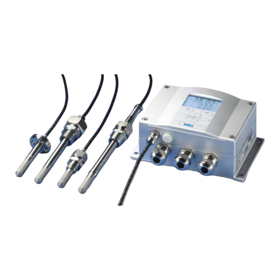
Page 23: Probe Options
DMT347 DMT348 small-size for high probe with for pressurized flanged probe pressure Swagelok pipelines for use with applications connector sampling cell 0503-019 Figure 3 Probe Options Probe cable lengths are 2 m, 5 m and 10 m. VAISALA _______________________________________________________________________ 21... - Page 24 USER'S GUIDE____________________________________________________________________ This page intentionally left blank. 22 __________________________________________________________________ M210704EN-F...
-
Page 25: Chapter 3 Installation
The housing can be mounted either without the mounting plate or with optional mounting plates. Standard Mounting without Mounting Plate Mount the housing without the mounting plate by fastening the transmitter to the wall with 4 screws, for example, M6 (not provided). 0804-066 Figure 4 Standard Mounting VAISALA _______________________________________________________________________ 23... -
Page 26: Wall Mounting With Wall Mounting Kit
USER'S GUIDE____________________________________________________________________ Wall Mounting with Wall Mounting Kit When mounting with wall mounting kit the mounting plate (Vaisala order code 214829) can be installed directly on wall or onto a standard wall box (also US junction box). When wiring through back wall, remove the plastic plug from the wiring hole in the transmitter before mounting. -
Page 27: Figure 7 Mounting With Metal Wall Mounting Plate
Mount the plate to wall with 4 screws M8 (not provided) Fasten DMT340 to the mounting plate with 4 fixing screws M6 (provided) Note the position of the arrow when mounting. This side must be up when mounting. 0509-151 Figure 8 Dimensions of Metal Mounting Plate (mm/inch) VAISALA _______________________________________________________________________ 25... -
Page 28: Mounting With Din Rail Installation Kit
Mounting with DIN Rail Installation Kit DIN rail installation kit includes a wall mounting kit, 2 clip-fasteners and 2 screws M4 x 10 DIN 7985 (Vaisala order code 215094). Attach two spring holders to the plastic mounting plate by using the screws provided in the installation kit. -
Page 29: Pole Installation With Installation Kit For Pole Or Pipeline
Pole Installation with Installation Kit for Pole or Pipeline Installation kit for pole or pipeline (Vaisala order code: 215108) includes the metal mounting plate and 4 mounting nuts for pole mounting. When mounting, the arrow in the metal mounting plate must point upward, see Figure 7 on page 25. -
Page 30: Mounting The Rain Shield With Installation Kit
Panel Mounting Frame To enable a neat and dirt free embedded installation of the transmitter, a panel mounting frame is available as an option (Vaisala order code: 216038). The frame is a thin, flexible plastic frame for the transmitter, with adhesive tape on one side. -
Page 31: Figure 13 Panel Mounting Frame
Refer to Figure 13 below. 0704-002 Figure 13 Panel Mounting Frame The numbers refer to Figure 13 above: = Panel (not included) = Panel mounting frame 0804-083 Figure 14 Panel Mounting Dimensions (mm/inch) VAISALA _______________________________________________________________________ 29... -
Page 32: Wiring
USER'S GUIDE____________________________________________________________________ Wiring Cable Bushings A single electrical cable with a screen and three to ten wires is recommended for power and analog/serial connections. The cable diameter should be 8 ... 11 mm. The number of cable bushings depends on the transmitter options. See the following recommendations for the cable bushings: 0503-010 Figure 15... -
Page 33: Grounding The Cables
Bend over the screen braiding or screen foil by about 90º (item 4). Push the seal insert with the contact socket of the gland (item 2+3) up to the screen braiding or screen foil. Mount the lower part (item 5) on the housing VAISALA _______________________________________________________________________ 31... -
Page 34: Transmitter Housing Grounding
USER'S GUIDE____________________________________________________________________ Push the seal with the contact socket of the gland and (item 2+3) flush into the lower part (item 5). Fasten the domed cap nut (item 1) onto the lower part (item 5). Transmitter Housing Grounding In case you need to ground the transmitter housing, the grounding connector is found inside the housing;... - Page 35 (-)). When wiring the power supply module, see section Power Supply Module on page 52. Turn on the power. The indicator LED on the cover lit continuously during normal operation. Close the cover and replace the cover screws. The transmitter is ready for use. VAISALA _______________________________________________________________________ 33...
-
Page 36: Connections To A 24 Vac Power Supply
USER'S GUIDE____________________________________________________________________ Connections to a 24 VAC Power Supply Separate floating supply for each transmitter is recommended (see the upper part of Figure 18 on page 34). If you have to connect several transmitters or other instruments to one AC supply, the phase (~) must always be connected to the (+) connector of each transmitter (see the lower part of Figure 18). -
Page 37: Probe Mounting
In this case, the ambient temperature must be at least 10 °C warmer than the process dewpoint in order to avoid condensation in the sample tubing. 0503-018 Figure 19 DMT342 Installation (without the Sampling Cell) VAISALA _______________________________________________________________________ 35... -
Page 38: Figure 20 Hmp302Sc Optional Sampling Cell
USER'S GUIDE____________________________________________________________________ 0503-017 Figure 20 HMP302SC Optional Sampling Cell The numbers refer to Figure 20 above: Gas in Probe Gas out Probe Sampling cell Clamp (not needed if sampling cell is supported on the piping) CAUTION In pressurized processes it is essential to tighten the supporting nuts and screws very carefully to prevent loosening of the probe by the action of pressure. -
Page 39: Dmt344 For High-Pressure Applications
Mark both the fitting screw and the nut hex. 0506-029 Figure 21 DMT344 Probe The numbers refer to Figure 21 above: Tightening cone Fitting screw, M22x1.5 or NPT 1/2" Sealing washer Probe; Ø12 mm VAISALA _______________________________________________________________________ 37... -
Page 40: Figure 22 Tightening The Nut
USER'S GUIDE____________________________________________________________________ Tighten the nut a further 30º (1/12) turn or if you have a torque spanner tighten it with a torque of 80 ± 10 Nm (60 ± 7 ft-lbs). 0503-034 Figure 22 Tightening the Nut NOTE When re-tightening the nut after detachment the nut must be tightened without increased effort. -
Page 41: Dmt347 Small Pressure-Tight Probe
Pressure-Tight Swagelok Installation Kits for DMT347 Swagelok installation kit for the dewpoint probe includes Swagelok connector with ISO1/2" thread (Vaisala order code: SWG12ISO12), ISO3/8" thread (Vaisala order code: SWG12ISO38) or NPT1/2" thread (Vaisala order code: SWG12NPT12). 0503-042 Figure 24 DMT347 Probe with Swagelok Installation Kit... -
Page 42: Figure 25 Dmt347 Probe Installation To Pipeline With Swagelok Installation Kit
USER'S GUIDE____________________________________________________________________ 0503-021 Figure 25 DMT347 Probe Installation to Pipeline with Swagelok Installation Kit The numbers refer to Figure 25 above: Probe Duct connector ISO1/2", ISO3/8" or NPT1/2" thread Swagelok connector Ferrules Preparing Installation. The connector options are the following: R3/8"... -
Page 43: Dmt348 For Pressurized Pipelines
Fitting body, 24 mm hex head Leak screw The following three fitting body options are available: - Fitting Body Set ISO1/2 with leak screw - Fitting Body ISO1/2 solid structure (without leak screw) - Fitting Body NPT1/2 solid structure (without leak screw) VAISALA _______________________________________________________________________ 41... -
Page 44: Figure 27 Leak Screw In The Dmt348 Probe
USER'S GUIDE____________________________________________________________________ 0503-005 Figure 27 Leak Screw in the DMT348 Probe The number refers to Figure 27 above: Non-leaking screw (A) (factory setting) or leak screw (B) (included in the package) Table 4 DMT348 Probe Dimensions Probe type Probe Dimension Adjustment Range Standard 178 mm... -
Page 45: Tightening The Clasp Nut
45 ± 5 Nm (33 ± 4 ft-lbs). 0505-276 Figure 29 Tightening the Clasp Nut The numbers refer to Figure 29 above: 1 = Probe 2 = Clasp nut 3 = Fitting screw 4 = Pen VAISALA _______________________________________________________________________ 43... - Page 46 USER'S GUIDE____________________________________________________________________ CAUTION Take care not to damage the probe body. A damaged body makes the probe less tight and may prevent it from going through the clasp nut. CAUTION In pressurized processes it is essential to tighten the supporting nuts and screws very carefully to prevent loosening of the probe by the action of pressure.
-
Page 47: Ball Valve Installation Kit For Dmt348
Chapter 3 _______________________________________________________________ Installation Ball Valve Installation Kit for DMT348 The ball valve installation kit (Vaisala order code: BALLVALVE-1) is preferred when connecting the probe to a pressurized process or pipeline. Use the ball valve set or a 1/2" ball valve assembly with a ball hole of ø14 mm or more. - Page 48 USER'S GUIDE____________________________________________________________________ NOTE The probe can be installed in the process through the ball valve assembly provided that the process pressure is less than 10 bars. This way, the process does not have to be shut down when installing or removing the probe.
-
Page 49: Leak Screw Installation
0503-036 Figure 31 Probe in Leak Screw Installation The numbers refer to Figure 31 above: Probe Filter Ball of the ball valve Leak screw VAISALA _______________________________________________________________________ 47... -
Page 50: Mounting The Probe Directly To The Process
(plugged) for Td field check reference measurement probe (for example, Vaisala DM70) If the probe is installed in process pipes where the water is likely to collect at the measurement point, take care to install the probe so that it will not be immersed in water. -
Page 51: Figure 33 Example Of Installing The Probe Directly On The Process Pipe
When the probe is pulled out for maintenance, cap the hole with a capped nut. This way, the process can be running although the probe is not in place. For ISO threaded connections, a plug (Vaisala order code 218773) is available. 0706-001 Figure 33... -
Page 52: Sampling Cell For Dmt348
10 °C warmer than the process dewpoint in order to avoid condensation in the sample tubing. Sampling Cell with Swagelok Connectors (Vaisala order code: DMT242SC2) and Sampling Cell with Female Connectors (Vaisala order code: DMT242SC) are available as an option. 0506-026... -
Page 53: Figure 35 Installing The Probe In High Temperatures
0503-022 Figure 35 Installing the Probe in High Temperatures VAISALA _______________________________________________________________________ 51... -
Page 54: Optional Modules
USER'S GUIDE____________________________________________________________________ Optional Modules Power Supply Module The mains power connection may be connected to the power supply module only by an authorized electrician. A readily accessible disconnect device shall be incorporated in the fixed wiring. 0506-027 Figure 36 Power Supply Module The numbers refer to Figure 36 above: Connect AC mains voltage wires to these terminals Grounding terminal... -
Page 55: Installation
Do not detach the power supply module from the transmitter when the power is on. WARNING Do not connect the mains power to power supply module when it is not installed in the transmitter. Always connect protective ground terminal. WARNING VAISALA _______________________________________________________________________ 53... -
Page 56: Warnings
USER'S GUIDE____________________________________________________________________ Warnings Dieses Produkt entspricht der Niederspannungsrichtlinie (2006/95/EWG). Das Netzmodul darf nur von einem dazu befugten Elektriker angeschlossen werden. Trennen Sie das Netzmodul nicht vom Messwertgeber, wenn der Strom eingeschaltet ist. Verbinden Sie das Netzmodul nur mit der Spannungsquelle, wenn es im Messwertgeber DMT340 montiert ist. - Page 57 Ez a termék megfelel a Kisfeszültségű villamos termékek irányelvnek (2006/95/EGK). A hálózati feszültséget csak feljogosított elektrotechnikus csatlakoztathatja a tápegységmodulra. A bekapcsolt távadóról ne csatolja le a tápegységmodult. Ne csatlakoztassa a hálózati feszültséget a tápegységmodulhoz, ha az nincs beépítve a DMT340 távadóba. Feltétlenül csatlakoztasson földelő védőkapcsot! VAISALA _______________________________________________________________________ 55...
- Page 58 USER'S GUIDE____________________________________________________________________ Šis produktas atitinka direktyvą dėl žemos įtampos prietaisų (2006/95/EB). Elektros tinklą su energijos tiekimo moduliu sujungti gali tik įgaliotas elektrikas. Niekada neišimkite energijos tiekimo modulio iš siųstuvo, kai maitinimas yra įjungtas. Jei energijos tiekimo modulis nėra įmontuotas DMT340 siųstuve, nejunkite jo į elektros tinklą.
-
Page 59: Galvanic Isolation For Output
= Output isolation module Third Analog Output 0503-030 Figure 38 Third Analog Output The numbers refer to Figure 38 above: Flat cable pins Screw terminals for signal line Dip switches to select the output mode and range VAISALA _______________________________________________________________________ 57... -
Page 60: Installation And Wiring
USER'S GUIDE____________________________________________________________________ Installation and Wiring Disconnect the power. In case the analog output module is installed in the factory, continue with the step 4. To attach the module, open the transmitter cover and fasten the analog output module to the position for MODULE 2 with four screws. -
Page 61: Alarm Relays
C and NO outputs are closed, NC is open. Connect the power and close the cover. For instructions on how to operate the relay (for example, selecting quantity for the relay output and setting the relay setpoints), see section Operation of Relays on page 129. VAISALA _______________________________________________________________________ 59... -
Page 62: Figure 40 Relay Module
USER'S GUIDE____________________________________________________________________ 0503-037 Figure 40 Relay Module The numbers refer to Figure 40 above: Indication led for the relay 1 or 3 Relay test buttons Flat cable pins Indication led for relay 2 or 4 WARNING The relay module may contain dangerous voltages even if the transmitter power has been disconnected. -
Page 63: Rs-422/485 Interface
A and B instead of D1+ and D0-. When the line is idle, D1+ has positive voltage compared to D0-. When connecting the module, be prepared to swap the D1+ and D0- wires if you have a communication problem. VAISALA _______________________________________________________________________ 61... -
Page 64: Installation And Wiring
USER'S GUIDE____________________________________________________________________ Installation and Wiring Disconnect the power. In case the RS-422/485-module is installed in the factory, continue with the item 4. To attach the module, open the transmitter cover and fasten the RS-422/485 module to the bottom of the housing with four screws. Connect the flat cable between the RS-422/485 module and the motherboard's pins MODULE1 (Communications). -
Page 65: Figure 42 4-Wire Rs-485 Bus
Baud > 112K Stub < 1ft, 0.3m 1102-028 Figure 42 4-Wire RS-485 Bus Table 6 4-Wire (Switch 3: On) RS-485 master Data DMT340 → Tx D1+ Rx D1+ → Tx D0- Rx D0- ← Rx D1+ Tx D1+ ← Rx D0- Tx D0- VAISALA _______________________________________________________________________ 63... -
Page 66: Figure 43 2-Wire Rs-485 Bus
USER'S GUIDE____________________________________________________________________ Termination 120R Common Stub RS485 bus master Junction box Address NN Switch Term off Term off Common 2/4 wire off RS422 off Stub RS485-1 Junction box Twisted pair Address MM Switch Term off Term off Common 2/4 wire off RS422 off 120R Stub... -
Page 67: Lan Interface
RS-232 User Port is disabled. The LAN interface module must be installed at the factory (when ordering the transmitter), or by a Vaisala Service Center. Once installed, the module is automatically used by the transmitter. The physical connection to the network is made to the RJ45 connector on the LAN interface module, using a standard twisted pair Ethernet cable (10/100Base-T). -
Page 68: Wlan Interface
USER'S GUIDE____________________________________________________________________ 0709-003 Figure 44 LAN Interface Module The numbers refer to Figure 44 above: Flat cable connector RJ45 connector with indicator LEDs for link and activity WLAN Interface The optional WLAN interface enables a wireless Ethernet connection (IEEE 802.11b) to the transmitter. The user can establish a virtual terminal session using a Telnet client program such as PuTTY or by using MODBUS TCP protocol. -
Page 69: Attaching The Wlan Antenna
Attaching the WLAN Antenna The LAN interface module must be installed at the factory (when ordering the transmitter), or by a Vaisala Service Center. Before taking the transmitter into use, you must attach the antenna of the WLAN interface into the RP-SMA connector on the transmitter cover. The location of the antenna is shown in Figure 92 on page 177. -
Page 70: Data Logger Module
USER'S GUIDE____________________________________________________________________ Data Logger Module The optional data logger module extends the data storage for the measurement data. When the data logger is present, this storage is automatically used by the transmitter. The stored data can be browsed using the optional display module, and accessed through the serial connections. -
Page 71: Figure 46 Data Logger Module
The data logger module must be installed at the factory (when ordering the transmitter), or by a Vaisala Service Center. Once installed, the module is automatically used by the transmitter. When the module requires a new battery, the transmitter must be sent to Vaisala for maintenance. VAISALA _______________________________________________________________________ 69... -
Page 72: 8-Pin Connector
USER'S GUIDE____________________________________________________________________ 8-Pin Connector 1104-126 Figure 47 Pinout of the Optional 8-Pin Connector Table 9 Wiring of the Optional 8-Pin Connector Wire Serial Signal Analog Signal RS-232 (EIA-232) RS-485 (EIA-485) White Data out TX Brown (Serial GND) (Serial GND) Signal GND (for both channels) Green Ch 2+... -
Page 73: Chapter 4 Operation
6 minutes due to the sensor self diagnostics procedure (Sensor Purge and Autocal). The frozen output value will be the value the DMT340 transmitter reached during the 10 seconds of measurement. After the self diagnostics procedure the outputs are operational again. VAISALA _______________________________________________________________________ 71... -
Page 74: Display/Keypad
USER'S GUIDE____________________________________________________________________ Display/Keypad Basic Display Display shows you the measurement values of the selected quantities in the selected units. You can select 1... 4 quantities for the numerical basic display (see section Changing the Quantities and Units on page 103). 0706-009 Figure 48 Basic Display... -
Page 75: Graphic History
The right upper corner shows the time from the present to the chosen moment (without the logger module), or the date and time at the cursor position (when the logger module is installed). VAISALA _______________________________________________________________________ 73... -
Page 76: Figure 50 Graphical Display With Data Logger
USER'S GUIDE____________________________________________________________________ - If the optional data logger module is installed, you can scroll the cursor off the screen to move to a new point on the time axis. The new date will be displayed, and the cursor will be centered at the date where the cursor scrolled off the screen. -
Page 77: Menus And Navigation
Adjustment menu is displayed only when ADJ button (on the motherboard inside the transmitter) is pressed. 0706-011 Figure 51 Main Views Some menu items, such as Relay outputs in the Interfaces menu, are only shown if supported by the transmitter and the installed options. VAISALA _______________________________________________________________________ 75... -
Page 78: Changing The Language
USER'S GUIDE____________________________________________________________________ Changing the Language Go back to the basic display by keeping the right-hand button pressed for four seconds. Open the Main menu by pressing any of the ▼▲◄► buttons. Scroll to the System menu option, and press the ► button. The menu option is indicated with the wrench symbol. -
Page 79: Display Contrast Setting
PIN code and select System, Menu PIN, press OFF button. In case you have forgotten the PIN code, open the transmitter cover and press the ADJ button once. Wait for a few seconds and the adjustment menu opens. Select Clear menu PIN, press CLEAR. VAISALA _______________________________________________________________________ 77... -
Page 80: Factory Settings
USER'S GUIDE____________________________________________________________________ NOTE You can also disable the keypad completely with serial command LOCK. See section Locking Menu/Keypad Using Serial Line on page 114. Factory Settings Use the display/keypad to restore the factory settings. This operation does not affect the adjustments. Only settings available in the menus are restored. -
Page 81: Configuring A Display Alarm
Enter the Main Menu by pressing an arrow key on the keypad. Use the arrow keys to select Display, followed by Alarms, to open the Display Alarms menu. The Display Alarms menu shows the currently enabled and disabled alarms. VAISALA _______________________________________________________________________ 79... -
Page 82: Figure 54 Display Alarms
USER'S GUIDE____________________________________________________________________ 0802-069 Figure 54 Display Alarms Use the arrow keys to select an alarm to configure. The alarm editing page opens. Changes you do on the alarm editing page will take effect immediately, NOTE and may cause an alarm to appear on the screen. To select a quantity for the alarm, press the Change button and select the quantity from the list. -
Page 83: Mi70 Link Program For Data Handling
Start using the program. There is usually no need to select a COM port manually, the MI70 Link software can detect it automatically. The MI70 Link program, and the optional connection cables, are available from Vaisala. See list of accessories in section Options and Accessories on page 174. VAISALA _______________________________________________________________________ 81... -
Page 84: Serial Line Communication
USER'S GUIDE____________________________________________________________________ Serial Line Communication Connect the serial interface by using either the user port or the service port. For permanent interfacing to host system, use the User Port. You can change the serial settings and operate in RUN, STOP, POLL, and MODBUS modes. -
Page 85: User Port Connection
- In POLL or MODBUS mode, the transmitter does not output anything after power-up. For a description of the modes, see section SMODE on page 117. NOTE RS-232 User Port cannot be used when a communication module (LAN, WLAN, or RS-422/485 Interface) has been installed. VAISALA _______________________________________________________________________ 83... -
Page 86: Service Port Connection
Link detects the USB connection automatically. There is no reason to uninstall the driver for normal use. However, if you wish to remove the driver files and all Vaisala USB cable devices, you can do so by uninstalling the entry for Vaisala USB Instrument Driver from the Add or Remove Programs (Programs and Features in Windows Vista) in the Windows Control Panel. -
Page 87: Using The Service Port
LAN and WLAN interfaces; refer to section List of Serial Commands on page 96. For instructions on how to connect using a terminal program, see section Terminal Program Settings on page 93. VAISALA _______________________________________________________________________ 85... -
Page 88: Ip Configuration
USER'S GUIDE____________________________________________________________________ IP Configuration The IP settings of the LAN and WLAN interfaces are described in Table 14. The current settings can be viewed on the serial line or using the device information display; see section Device Information on page 110. Table 14 IP Settings for the LAN and WLAN Interfaces Parameter... -
Page 89: Figure 58 Network Interface Menu
Move the cursor using the ◄► arrow buttons, and change the value under the cursor using the ▲▼ arrow buttons. Confirm the selection by pressing OK. After configuring the desired parameters, press EXIT to apply the changes and return to the basic display. VAISALA _______________________________________________________________________ 87... -
Page 90: Using Serial Line
USER'S GUIDE____________________________________________________________________ Using Serial Line Use the serial line command NET to view or set the network settings for the LAN and WLAN interfaces. You can also refresh the network information or disconnect all active connections. NET [REFRESH] [DISCONNECT] [DHCP WEB] [DHCP IP SUBNET GATEWAY WEB]<cr>... -
Page 91: Wireless Lan Configuration
The security type of the wireless network. The options are: OPEN OPEN/WEP WPA-PSK/TKIP WPA-PSK/CCMP All other choices except OPEN require a security key; see below. Security key The encryption key or passphrase that is used with an encrypted network. VAISALA _______________________________________________________________________ 89... -
Page 92: Using Display/Keypad
USER'S GUIDE____________________________________________________________________ Using Display/Keypad You can configure the Wireless LAN settings using the display/keypad as follows: Press any of the arrow buttons to open the Main Menu. Press the ► arrow button to select Interfaces. Press the ► arrow button to select Network settings. There will be a delay as the transmitter refreshes the network information. -
Page 93: Using Serial Line
Security type of the wireless network. The options are: OPEN OPEN/WEP WPA-PSK/TKIP WPA-PSK/CCMP Examples: >wlan ? Network SSID : WLAN-AP Type : OPEN > >wlan accesspoint wpa-psk/tkip Network SSID : accesspoint Type : WPA-PSK/TKIP WPA-PSK phrase ? thequickbrownfox Save changes (Y/N) ? y > VAISALA _______________________________________________________________________ 91... -
Page 94: Communication Protocol
When accessing the web configuration page, you must first log in. Username: user Password: vaisala The web configuration page provides similar network configuration options as the serial line and the display/keypad. It also has additional options for advanced users. For example, there are more options for securing the wireless network. -
Page 95: Terminal Program Settings
The instructions below describe how to connect to the DMT340 using the PuTTY terminal application for Windows. Perform the necessary cabling and configuration of the transmitter before following the instructions. PuTTY is available for download at www.vaisala.com. NOTE PuTTY cannot be used to access the transmitter through the User Port if the transmitter is configured to use the MODBUS protocol. -
Page 96: Opening A Serial/Usb Connection
COM port is selected in the Serial or USB line to connect to field. Change the port if necessary. If you are using a Vaisala USB cable, you can check the port that it uses by clicking the USB Finder... button. This opens the Vaisala USB Instrument Finder program that has been installed along with the USB drivers. -
Page 97: Opening A Telnet Session (Lan/Wlan)
Telnet session. If PuTTY is unable to connect the IP address you entered, it will show you an error message instead. If this happens, check the IP address and the connections, restart PuTTY, and try again. VAISALA _______________________________________________________________________ 95... -
Page 98: List Of Serial Commands
USER'S GUIDE____________________________________________________________________ List of Serial Commands All commands can be issued either in uppercase or lowercase. In the command examples, the keyboard input by the user is in bold type. The notation <cr> refers to pressing the carriage return (Enter) key on your computer keyboard. -
Page 99: Table 18 Data Recording Commands
Configure analog output quantities and scales ITEST Test analog outputs AMODE Display analog output mode AERR Change the error output ASCL Analog output scaling Table 23 Setting and Testing the Relays Command Description RSEL Configure relay settings RTEST Test relays VAISALA _______________________________________________________________________ 97... -
Page 100: Table 24 Other Commands
USER'S GUIDE____________________________________________________________________ Table 24 Other Commands Command Description Output the information about the device Output the information about the device in POLL-state CDATE Adjust the output date/set date when adjustment enabled CODE Display the order configuration code of the transmitter CTEXT Display the adjustment information text/set information text when adjustment enabled... -
Page 101: Getting The Measurement Message From Serial Line
Outputting Reading Once Use the SEND command to output the reading once in STOP mode. The output format depends on which parameters the transmitter can output. SEND<cr> Examples: >send Tdf= -5.8 'C H2O= 3715 ppmV x= 2.3 g/kg VAISALA _______________________________________________________________________ 99... -
Page 102: Assign An Alias For The Send Command
USER'S GUIDE____________________________________________________________________ >send Tdf= -5.9 'C Td= -6.6 'C Tdfa= -5.9 'C Tda= -6.6 'C H2O= 3696 ppmV x= 2.3 g/kg RH= 13.9 %RH a= 2.7 g/m3 aNTP= 3.0 g/m3 T= 22.2 'C dT= 28.1 'C Assign an Alias for the SEND Command Use the SCOM command to assign a new command that works like the SEND command. -
Page 103: Formatting Serial Line Message
>ftime on Form. time : ON >send 23:08:27 Tdf=-20.6 'C H2O= 959 ppmV T= 23.9 'C RH= >fdate on Form. date : ON >send 2000-01-31 23:08:46 Tdf=-20.6 'C H2O= 960 ppmV T= 23.9 'C 3.3 %RH > VAISALA ______________________________________________________________________ 101... -
Page 104: Fst
USER'S GUIDE____________________________________________________________________ Use the FST command to include the status of purge, sensor warming and AutoCal in output from the SEND and R commands. FST [x]<cr> where = ON or OFF (default) Example: >fst on Form. status : ON >send 0 RH= 40.1 %RH T= 24.0 'C Td= 9.7 'C Tdf= 9.7 'C a=... -
Page 105: General Settings
CHANGE. The unit changes from metric to non-metric or the other way round. Press EXIT to return to the basic display. Changing the units by using the display/keypad has no effect on the NOTE serial output units. VAISALA ______________________________________________________________________ 103... -
Page 106: Using Serial Line
USER'S GUIDE____________________________________________________________________ Using Serial Line Use the serial line command FORM to change the format, and the command UNIT to select metric or non-metric output units. FORM Use the serial line command FORM to change the format or select a certain quantities for the output commands SEND and R. -
Page 107: Unit
PPMW (parts per million by weight) This command changes both the serial output and display units. When NOTE you want to output both metric and non-metric units simultaneously on the display, select the display units later by using the display/keypad. VAISALA ______________________________________________________________________ 105... -
Page 108: Pressure Compensation Setting
O at 4°C. NOTE Pressure compensation is intended to be used in normal air only. When measuring in other gases, please contact Vaisala for further information. Fixed pressure compensation value of 1013.25 hPa is used when in NOTE adjustment mode. -
Page 109: Using Buttons On The Motherboard
Its value is not retained at reset, and when set to 0; last value set with PRES is used instead. Use the serial line and do the following: PRES [aaaa.a]<cr> XPRES [aaaa.a]<cr> where aaaa.a = Absolute process pressure (hPa) VAISALA ______________________________________________________________________ 107... -
Page 110: Date And Time
USER'S GUIDE____________________________________________________________________ Example: >pres Pressure : 1013.00 hPa ? >pres 2000 Pressure : 2000.00 hPa > Table 26 Conversion Factors for Pressure Units From To: hPa mbar PaN/m2 0.01 mmHg torr 1.333224 inHg 33.86388 0.09806650 2.490889 1013.25 980.665 1000 psia 68.94757 1) Psia = psi absolute. -
Page 111: Using Serial Line
Press any of the arrow buttons to open the Main Menu. Select Measuring by pressing the ► arrow button. Select Filtering and press CHANGE to confirm your selection. Select Off/Standard/Extended and press SELECT to confirm your selection. Press EXIT to return to the basic display. VAISALA ______________________________________________________________________ 109... -
Page 112: Filt
USER'S GUIDE____________________________________________________________________ FILT Use FILT command to set the output filtering level. FILT [xxx]<cr> where OFF, ON, or EXT (default = ON) Device Information Use the display/keypad or the serial line to display the device information. Press the INFO button in the basic display to see the following information: - Current sensor operation (for example, AutoCal or Purge) in progress - Present or past unacknowledged errors... - Page 113 Ch2 output : 0...1V Ch1 Tdf : -20.00 'C Ch1 Tdf high : 100.00 'C Ch2 H2O : 0.00 ppmV Ch2 H2O high : 5000.00 ppmV Module 1 : not installed Module 2 : not installed > VAISALA ______________________________________________________________________ 111...
-
Page 114: Light
USER'S GUIDE____________________________________________________________________ LIGHT Use the LIGHT command to view or set the backlight mode of the display (optional). Issuing the command without specifying a mode shows the current backlight mode. LIGHT [mode]<cr> where mode = Operating mode of the display backlight. The options are: ON (backlight always on) OFF (backlight always off) AUTO (backlight automatically turns on and off when... -
Page 115: Errs
Use the VERS command to display software version information. Example: >vers DMT340 / 5.10 > Resetting the Transmitter Using Serial Line RESET The RESET command resets the transmitter. The user port switches to start-up output mode selected with command SMODE. VAISALA ______________________________________________________________________ 113... -
Page 116: Locking Menu/Keypad Using Serial Line
USER'S GUIDE____________________________________________________________________ Locking Menu/Keypad Using Serial Line LOCK Use the LOCK command to prevent the user from entering the menu using the keypad, or to lock the keypad completely. You can optionally set a 4-digit PIN code, for example 4444. If a PIN code has been set, the user will be prompted to enter the code when trying to access the menu. -
Page 117: Serial Output Settings
Select the Device address and press SET to confirm. Select ECHO, and press ON to turn to it on, OFF to turn it off. Press EXIT to return to the basic display. The new user port settings set using the display/keypad are effective immediately. VAISALA ______________________________________________________________________ 115... -
Page 118: Using Serial Line
USER'S GUIDE____________________________________________________________________ Using Serial Line NOTE You can use the serial commands to change/view the user port settings even if you are currently connected to the service port. SERI Use the SERI command to set the communication settings for the user port. -
Page 119: Smode
Addresses are required for POLL mode and MODBUS mode (serial MODBUS). ADDR [aa]<cr> where aa = Device address of the transmitter, range 0 ... 255 (default = 0) Example (changing the transmitter address from 0 to 52): >addr Address : 0 ? 52 > VAISALA ______________________________________________________________________ 117... -
Page 120: Intv
USER'S GUIDE____________________________________________________________________ INTV Use the INTV command to set the RUN mode output interval. The time interval is used only when the RUN mode is active. INTV [xxx yyy]<cr> where = Delay, range 1 – 255. = Unit: S, MIN or H. Example (setting the output interval to 10 minutes): >intv 10 min Output interval: 10 min... -
Page 121: Echo
ON (enabled, default) or OFF (disabled) When using the RS-485 Interface with a 2-wire connection, always NOTE disable echo. When using a RS-232, RS-422/485 4-wire connection, LAN, or WLAN, you can enable or disable it as you wish. VAISALA ______________________________________________________________________ 119... -
Page 122: Data Recording
USER'S GUIDE____________________________________________________________________ Data Recording Data recording function is always on and collects data automatically into the memory of the device. If the optional data logger module is installed, the transmitter uses it automatically. Recorded data does not disappear from the memory when the power is switched off. Collected data can be observed in a form of a graph in the graphical view of the display or it can be listed out by using the serial line or MI70 Link program. -
Page 123: View Recorded Data
(12 h intervals) 2008-02-04 12:03:41 (3 d intervals) 2007-03-04 00:03:41 (90 s intervals) 2008-04-11 20:41:11 (12 min intervals) 2008-04-10 21:03:41 (2 h intervals) 2008-03-31 18:03:41 (12 h intervals) 2008-02-04 12:03:41 10 Tdf (3 d intervals) 2007-03-04 00:03:41 > VAISALA ______________________________________________________________________ 121... -
Page 124: Play
USER'S GUIDE____________________________________________________________________ PLAY Use the PLAY command to output the selected file to the serial line. If the data logger module is installed, you can specify an interval to be outputted. Data in the output is <TAB> delimited. This is compatible with most spreadsheet programs. -
Page 125: Deleting The Recorded Files
Figure 2 on page 20 (dip switches for analog output settings). Select the current/voltage output, switch ON either of the switches, 1 or 2. Select the range,switch ON one of the switches from 3 to 7. VAISALA ______________________________________________________________________ 123... -
Page 126: Figure 68 Current/Voltage Switches Of Output Modules
USER'S GUIDE____________________________________________________________________ 0503-045 Figure 68 Current/Voltage Switches of Output Modules The numbers refer to Figure 68 above: Current/voltage selection output switches (from 1 to 2) Current/voltage range selection switches (from 3 to 7) in analog output 1 and 2 Switches for service use only. Keep in OFF position always. NOTE Only set one mode and one range switch to ON for one output channel. -
Page 127: Analog Output Quantities
CHANGE. Select the quantity by using the arrow buttons. Press SELECT to confirm your selection. Select Scale, lower limit, by pressing the ▲▼arrow buttons. Press SET to confirm your selection. Press OK to confirm your setting. VAISALA ______________________________________________________________________ 125... -
Page 128: Amode/Asel
USER'S GUIDE____________________________________________________________________ Select the upper limit by pressing the ▲▼arrow buttons. Use the arrow buttons to set the upper limit value. Press SET to confirm your selection. Press OK to confirm your setting. Press EXIT to return to the basic display. AMODE/ASEL Use the serial line to select and scale the analog output quantities. -
Page 129: Analog Output Tests
= Current or voltage value to be set for channel 3 (optional) (mA or V) Example: >itest 20 5 Ch1 (Td ) 20.000 mA H'672A Ch2 (T 5.000 mA H'34F9 >itest Ch1 (Td ) -23.204 'C 16.238 mA H'FFFE Ch2 (T 22.889 'C 8.573 mA H'5950 > VAISALA ______________________________________________________________________ 127... -
Page 130: Analog Output Fault Indication Setting
USER'S GUIDE____________________________________________________________________ Analog Output Fault Indication Setting Factory default state for analog outputs during error condition is 0 V/ 0mA. Please be careful when selecting the new error value. The error state of the transmitter should not cause unexpected problems in process monitoring. -
Page 131: Operation Of Relays
"below" value, the relay is passive when the measured value is not between the setpoints. You can also set only one setpoint. See Figure 69 on page 130 for illustrative examples of the different measurement-based relay output modes. VAISALA ______________________________________________________________________ 129... -
Page 132: Figure 69 Measurement-Based Relay Output Modes
USER'S GUIDE____________________________________________________________________ 1102-007 Figure 69 Measurement-Based Relay Output Modes Mode 4 is usually used if an alarm needs to be triggered when the measured value exceeds a safe range. The relay is active when measurement is in range, and is released if the value goes out of range or the measurement fails. -
Page 133: Hysteresis
FAULT STATUS Normal operation: relay active (C and NO outputs are closed) Not measuring state (error state or power off): relay released (C and NC outputs are closed) VAISALA ______________________________________________________________________ 131... -
Page 134: Figure 70 Fault/Online Status Relay Output Modes
USER'S GUIDE____________________________________________________________________ ONLINE STATUS Live measurement (data available): relay active (C and NO outputs are closed) No live data (for example: error state, sensor purge or adjustment mode): relay released (C and NC outputs are closed) See Figure 70 on page 132 for illustrative examples of the FAULT/ONLINE STATUS relay output modes. -
Page 135: Enabling/Disabling The Relays
* Hysteresis has an effect when relay switching is based on live measurement. Hysteresis See section on page 131. Enabling/Disabling the Relays You can deactivate the relay outputs for example for service purposes of your system. VAISALA ______________________________________________________________________ 133... -
Page 136: Operation Of The Indication Leds
USER'S GUIDE____________________________________________________________________ Operation of the Indication LEDs Relay is activated: LED is lit. Relay is not activated: LED is not lit. Setting the Relay Outputs NOTE When you have only one relay module installed, its relays are called “relay 1” and “relay 2”. When you have two relay modules, the relays of the module connected to slot MODULE 1 are called “relay 1”... -
Page 137: Rsel
: 0.00 'C ? 5 Rel1 Tdf enabl: OFF ? on Rel2 T above: - ? 30 Rel2 T below: - ? 20 Rel2 T hyst : 0.00 'C ? 1 Rel2 T enabl: OFF ? on > VAISALA ______________________________________________________________________ 135... - Page 138 USER'S GUIDE____________________________________________________________________ Example of normal limit switch (one setpoint for relay activation/deactivation): Selecting relay 1 to follow relative humidity, relay 2 to follow temperature, relay 3 to follow dewpoint, and relay 4 to follow dewpoint. One setpoint is chosen for all the outputs. >rsel rh t td td Rel1 RH above: 60.00 %RH ? 70...
-
Page 139: Testing The Operation Of Relays
Use the serial line command RTEST to test the operation of the relays. RTEST [ON/OFF ON/OFF]<cr> Example: Testing all four relays. >rtest on on on on ON ON ON ON > >rtest off off off off OFF OFF OFF OFF Enter the command RTEST to stop testing. VAISALA ______________________________________________________________________ 137... -
Page 140: Sensor Functions
USER'S GUIDE____________________________________________________________________ Sensor Functions AutoCal To obtain the best possible accuracy in measurements taken in dry environments, DMT340 has a built-in AutoCal. During the AutoCal, DMT340 adjusts the dry-end reading to correspond to the calibrated values. This is a unique and patented method to avoid errors in accuracy when monitoring low dewpoints. -
Page 141: Manual Autocal
Purge can also be started manually. If enabled, power-up Purge will start always about 10 seconds after reset. If the power is continuously turned on in DMT340, the automatic sensor Purge will be performed at an interval of 24 hours. VAISALA ______________________________________________________________________ 139... -
Page 142: Starting And Configuring Sensor Purge
USER'S GUIDE____________________________________________________________________ A sensor purge should be performed always before calibration (see the calibration instructions) or when there is a reason to believe that a sensor has become exposed to an interfering chemical. Starting and Configuring Sensor Purge Using Display/Keypad (Optional) Open the Main Menu by pressing any of the ▼▲◄►... -
Page 143: Using Serial Line
Do not change the settings for duration, settling, temperature, temperature difference, or purge triggering unless instructed by Vaisala personnel. Type PUR and press ENTER to proceed. Skip unchanged values by pressing ENTER. -
Page 144: Sensor Warming
USER'S GUIDE____________________________________________________________________ Example (no data logger module installed): >pur Interval Purge : ON ? Interval : 1440 min ? Power-up Purge : ON ? Duration : 120 s ? Settling : 240 s ? Temperature : 160 'C ? Temp. diff. : 0.5 'C ? Trigger Purge : OFF ? -
Page 145: Chapter 5 Modbus
Design the system so that only one MODBUS TCP client accesses the transmitter. - MODBUS TCP can process reliably only one MODBUS transaction at a time. Reduce the polling rate of the client to avoid nested transactions. VAISALA ______________________________________________________________________ 143... -
Page 146: Taking Modbus Into Use
(optional) or a PC connected to the serial line. For example, you can connect to the service port using the USB service cable (Vaisala order code: 219685). The transmitter must be powered from a suitable power supply during configuration. -
Page 147: Enabling Serial Modbus
Connect the USB service cable between a computer and the service port of the transmitter. Start the Vaisala USB Instrument Finder program (which has been installed on the computer along with the USB service cable driver), and check the COM port that the cable is using. - Page 148 USER'S GUIDE____________________________________________________________________ Open a terminal program, and connect to the service port. The fixed settings serial line settings of the service port are 19200, 8, 1, N. Use the SMODE command to enable the MODBUS mode: > smode modbus Serial mode : MODBUS >...
-
Page 149: Enabling Ethernet Modbus
WLAN interface, select Wireless LAN Settings. On the Wireless LAN Settings screen, set the network name (SSID) and security options, and exit to save the changes. 1101-036 Figure 77 Wireless LAN Settings Navigate back to the Network Settings menu. Select Communication Protocol. VAISALA ______________________________________________________________________ 147... -
Page 150: Using Serial Line
Connect the USB service cable between a computer and the service port of the transmitter. Start the Vaisala USB Instrument Finder program (which has been installed on the computer along with the USB service cable driver), and check the COM port that the cable is using. - Page 151 For a description of the available settings, see section Wireless LAN Configuration on page 89. The MODBUS configuration is now complete. Reset or power cycle the transmitter to enable the MODBUS mode, and proceed with the installation of the transmitter. VAISALA ______________________________________________________________________ 149...
-
Page 152: Diagnostic Modbus Counters
USER'S GUIDE____________________________________________________________________ Diagnostic MODBUS Counters DMT340 has diagnostic counters that can be used to pinpoint MODBUS problems. The counters are always active when the MODBUS protocol is enabled. Viewing Counters Using Display/Keypad You can use the display/keypad option to view and clear the counters. Enter the Main Menu and navigate to System ►... -
Page 153: Disabling Modbus
Alternatively, you can enter the Main Menu using the display/keypad option, and change the mode from the Interfaces submenu. The other communication settings of the output interface (User Port, LAN interface, or WLAN interface) will remain as configured, but the MODBUS protocol will be disabled. VAISALA ______________________________________________________________________ 151... - Page 154 USER'S GUIDE____________________________________________________________________ This page intentionally left blank. 152 _________________________________________________________________ M210704EN-F...
-
Page 155: Chapter 6 Maintenance
Install a new filter on the probe. When using the stainless steel filter, take care to tighten the filter properly (recommended force 5 Nm). New filters can be ordered from Vaisala, see Available Options and Accessories Table 33 on page 174. Calibration and Adjustment The DMT340 is fully calibrated and adjusted as shipped from factory. -
Page 156: Error States
Press the INFO button to display the error message. You can also check the error message via the serial interface by using the command ERRS. In case of constant error, please contact Vaisala Technical Support. See section Technical Support on page 156. 154 _________________________________________________________________ M210704EN-F... -
Page 157: Table 31 Error Messages
Temperature sensor current leak. Internal ADC read error Internal transmitter failure. Remove the transmitter and return the faulty unit to Vaisala Service. Checksum error in the Internal transmitter failure. Remove the internal configuration transmitter and return the faulty unit to Vaisala memory Service. -
Page 158: Technical Support
USER'S GUIDE____________________________________________________________________ Technical Support For technical questions, contact the Vaisala technical support by e-mail at helpdesk@vaisala.com. Provide at least the following supporting information: - Name and model of the product in question - Serial number of the product - Name and location of the installation site... -
Page 159: Calibration And Adjustment
It is recommended that the device is sent to a Vaisala Service Center for calibration and adjustment. For contact information of Vaisala Service Centers, see www.vaisala.com/services/servicecenters.html. -
Page 160: Opening And Closing The Adjustment Mode
USER'S GUIDE____________________________________________________________________ ® For the adjustment of DMT340 equipped with DRYCAP 180M-sensor, the reference low dewpoint temperature should be between -57 °C and - 67 °C (-70.6 °F ... -88.6 °F) in the gas temperature of approx. +20 °C. To ensure the correctness of the adjustment, the reference dewpoint meter must be calibrated at a recognized laboratory with a known uncertainty and traceability to national or international standards. -
Page 161: Adjustment Information
Use the CDATE command to input date to the adjustment information field. Set the adjustment date in format YYYY-MM-DD. Example: >cdate Adjust. date : (not set) ? 2004-05-21 > Press the adjustment button on the motherboard inside the transmitter to disable the adjustment function. VAISALA ______________________________________________________________________ 159... -
Page 162: Adjusting Dewpoint Two-Point
USER'S GUIDE____________________________________________________________________ Adjusting Dewpoint T Before adjusting dewpoint, first carry out the two-point relative humidity adjustment, which will ensure the basic adjustment level. After that, continue with the actual T adjustment. Two-Point Relative Humidity Adjustment using Display/Keypad For DMT340 M-sensor, the humidity references of 0 % (for example Nitrogen) and 10 ... -
Page 163: Figure 83 Following The Rh Trend On Graphical Display
Figure 82 on page 160. Press READY when stabilized. Use the arrow buttons to enter the actual humidity of the reference used. Follow the instructions on the display to complete the RH adjustment. 0706-023 Figure 86 Completing Adjustment of Point 2 VAISALA ______________________________________________________________________ 161... -
Page 164: Two-Point Relative Humidity Adjustment Using Serial Line
USER'S GUIDE____________________________________________________________________ Two-Point Relative Humidity Adjustment using Serial Line Perform purge before adjustment. Use the PURGE command. See section PURGE on page 141. Then press adjustment button on the motherboard inside the transmitter to enable adjustments Perform adjustment with the FCRH command. Wait at least 1 hour before adjusting each point. -
Page 165: Figure 87 Following Stabilization
After adjustment wait for sensor to cool down which will take 2 minutes at the maximum. The adjustment is now completed. NOTE Several AutoCals can be necessary after this adjustment has been performed until the transmitter reaches full accuracy. VAISALA ______________________________________________________________________ 163... -
Page 166: One-Point Dewpoint Adjustment Using Serial Line
USER'S GUIDE____________________________________________________________________ One-Point Dewpoint Adjustment using Serial Line Let the sensor stabilize for at least 5 hours. Use the PURGE command to start the manual purge. See section PURGE on page 141. Wait at least 1 hour. Then press adjustment button on the motherboard inside the transmitter to enable adjustments. -
Page 167: Adjusting Temperature
Note that the difference between the two temperature references must be at least 30 ºC. Press OK. Press YES to confirm the adjustment. Press OK to return to the adjustment menu Press EXIT to return to the basic display. VAISALA ______________________________________________________________________ 165... -
Page 168: Adjusting Temperature Using Serial Line
USER'S GUIDE____________________________________________________________________ Adjusting Temperature using Serial Line Use the serial line command CT to adjust the temperature. Press the ADJ button on the motherboard to open the adjustment mode. Remove the probe filter and insert the probe into the reference temperature. -
Page 169: Adjusting Analog Outputs
Measure the second analog output value with a multimeter. Enter the measured value by using the arrow buttons. Press OK. Press OK to return to the adjustment menu. Press EXIT to close the adjustment and to return to the basic display. VAISALA ______________________________________________________________________ 167... -
Page 170: Adjusting Analog Outputs Using Serial Line
USER'S GUIDE____________________________________________________________________ Adjusting Analog Outputs using Serial Line ACAL Use the serial line to perform the analog output adjustment. Use the ACAL command and enter the multimeter reading. ACAL<cr> Example (current outputs): >ACAL (mA) ? 2.046 (mA) ? 18.087 (mA) ? 2.036 (mA) ? 18.071... -
Page 171: Chapter 8 Technical Data
-70 ... +45 °C (-94 ... +113 °F) Td Accuracy up to 20 bar / 290 psia see the accuracy graph 20 ... 50 bar / 290 ... 725 psia +1 °C Td Temperature of measured gas (°C) 0503-039 Figure 90 Dewpoint Accuracy Graph VAISALA ______________________________________________________________________ 169... -
Page 172: Operating Environment
USER'S GUIDE____________________________________________________________________ Response time 63% [90%] at +20°C gas temperature Flow rate 1 l/min and 1 bar pressure -60 -> -20 °C Td (-76 -> -4 °F Td) 5s [10s] -20 -> -60 °C Td (-4 -> -76 °F Td) 45s [10min] Temperature Measurement range... -
Page 173: Mechanics
0 … 10 bar / 0 ... 145 psia DMT348 0 … 40 bar / 0 ... 580 psia with Ball Valve 0 … 20 bar / 290 psia * Mechanical durability up to +180 °C (+356 °F) VAISALA ______________________________________________________________________ 171... -
Page 174: Technical Specifications Of Optional Modules
USER'S GUIDE____________________________________________________________________ Technical Specifications of Optional Modules Power Supply Module Operating voltage 100 ... 240 VAC 50/60 Hz Connections screw terminals for 0.5 ... 2.5 mm wire (AWG 20 ... 14) Bushing for 8 ... 11 mm diameter cable Operating temperature -40 ... -
Page 175: Rs-485 Module
13.7 million points / parameter Accuracy of the clock better than ± 2 min/year Battery lifetime at -40 ... +30 ºC (-40 ... +86 ºF) 7 years at +30 ... +60 ºC (+86 ... +140 ºF) 5 years VAISALA ______________________________________________________________________ 173... -
Page 176: Options And Accessories
USER'S GUIDE____________________________________________________________________ Options and Accessories Table 33 Options and Accessories Description Order Code MODULES Relay module RELAY-1 Analog Output Module AOUT-1 Isolated RS485 Module RS485-1 Power Supply Module POWER-1 Galvanic Isolation Module DCDC-1 FILTERS Sintered Filter AISI 316L HM47280SP Stainless Steel Filter HM47453SP TRANSMITTER MOUNTING ACCESSORIES Wall Mounting Kit... - Page 177 Cable Gland M20×1.5 for 11 ... 14mm Cable 214729 Conduit Fitting M20×1.5 for NPT1/2 Conduit 214780SP Dummy Plug M20×1.5 214672SP WINDOWS SOFTWARE Software Interface Kit 215005 OTHER HMK15 Calibration Adapter for 211302SP 12 mm Probes with >7 mm Sensor Pins VAISALA ______________________________________________________________________ 175...
-
Page 178: Dimensions (Mm/Inch)
USER'S GUIDE____________________________________________________________________ Dimensions (mm/inch) 0506-035 Figure 91 DMT340 Transmitter Body Dimensions 176 _________________________________________________________________ M210704EN-F... -
Page 179: Figure 92 Wlan Antenna Dimensions
Chapter 8 ____________________________________________________________ Technical Data 0804-035 Figure 92 WLAN Antenna Dimensions 0506-034 Figure 93 Sampling Cell Dimensions VAISALA ______________________________________________________________________ 177... -
Page 180: Figure 94 Dmt342 Probe Dimensions
USER'S GUIDE____________________________________________________________________ 0503-044 Figure 94 DMT342 Probe Dimensions 0804-059 Figure 95 DMT344 Probe Dimensions 178 _________________________________________________________________ M210704EN-F... -
Page 181: Figure 96 Dmt347 Probe Dimensions
Chapter 8 ____________________________________________________________ Technical Data 0804-129 Figure 96 DMT347 Probe Dimensions 0704-054 Figure 97 DMT348 Standard Probe Dimensions VAISALA ______________________________________________________________________ 179... -
Page 182: Figure 98 Npt 1/2" Nut Dimensions
USER'S GUIDE____________________________________________________________________ 0704-056 Figure 98 NPT 1/2" Nut Dimensions 0704-055 Figure 99 DMT348 Optional 400mm Probe Dimensions 180 _________________________________________________________________ M210704EN-F... -
Page 183: Appendix Acalculation Formulas
7.5000 237.3 50 ... 100 °C 5.9987 7.3313 229.1 100 ... 150 °C 5.8493 7.2756 225.0 150 ... 180 °C 6.2301 7.3033 230.0 1) Used for frostpoint calculation if the dewpoint is negative Mixing ratio: VAISALA ______________________________________________________________________ 181... - Page 184 USER'S GUIDE____________________________________________________________________ Absolute humidity: Enthalpy: . 1 ( 00189 The water vapour saturation pressure P is calculated by using two equations (5 and 6): where: temperature in K coefficients 0.4931358 -0.46094296 * 10 -2...
- Page 185 Symbols: Td = dewpoint temperature (°C) Pw = water vapour pressure (hPa) Pws = water vapour saturation pressure (Pa) RH = relative humidity (%) mixing ratio (g/kg) atmospheric pressure (hPa) absolute humidity (g/m3) temperature (K) enthalpy (kJ/kg) VAISALA ______________________________________________________________________ 183...
- Page 186 USER'S GUIDE____________________________________________________________________ This page intentionally left blank. 184 _________________________________________________________________ M210704EN-F...
-
Page 187: Modbus Reference
2 commands are also supported giving better compatibility and allowing more efficient communication when needed. MODBUS diagnostic and device identification data can be read out only with the function codes dedicated for those purposes (08 and 43 / 14). VAISALA ______________________________________________________________________ 185... -
Page 188: Register Map
USER'S GUIDE____________________________________________________________________ Register Map All data available via the MODBUS interface is grouped in six contiguous blocks of registers as described in Table 35 below. Table 35 DMT340 MODBUS Register Blocks Address Data Format Description 0001…0068 32-bit IEEE float Measurement data (read-only) 0257…0290 16-bit signed integer 0513…0517... -
Page 189: 16-Bit Integer Format
However, most of the measurement data values do not need any offset. A zero 16-bit value is returned for unavailable values. There is no way to distinguish missing values from actual zero values if the zero value is included in the valid measurement range of the parameter. VAISALA ______________________________________________________________________ 187... -
Page 190: Measurement Data (Read-Only)
USER'S GUIDE____________________________________________________________________ NOTE If your MODBUS master supports 32-bit floating point values, always use them instead of 16-bit integer registers. The use of 16-bit integer values is not recommended in critical applications because you cannot distinguish true zero values from zero values generated by measurement failures. -
Page 191: Status Registers (Read-Only)
0771...0772 (1026) instead of the permanent setting at register 0769…0770 (1025). Set the temporary value to zero to return to the default pressure setting. Non-metric units are not available on MODBUS. If they are needed, calculate the conversion outside the transmitter. VAISALA ______________________________________________________________________ 189... -
Page 192: Exception Status Outputs
USER'S GUIDE____________________________________________________________________ Configuration flags are used to select some basic options of the instrument and to manually start the sensor operations. Table 39 Configuration Flag Registers Name Address Description Standard filtering on/off 1281 1 = Filtering on Extended filtering on/off 1282 1 = Extended filtering on Automatic sensor purge on/off... -
Page 193: Diagnostic Sub-Functions
DMT340 supports the same diagnostic functions also on MODBUS TCP. NOTE Resetting, powering up the transmitter, or reselecting the MODBUS mode (by serial command or with the user interface) resets all MODBUS diagnostic counters and cancels any “Listen Only” mode. VAISALA ______________________________________________________________________ 191... -
Page 194: Device Identification Objects
MODBUS Application Protocol Specification V1.1b. Both stream access and individual access to the objects is supported. Table 42 DMT340 MODBUS Device Identification Object Id Object Name Description 0x00 VendorName “Vaisala” 0x01 ProductCode Product code (e.g. “DMT340”) 0x02 MajorMinorVersion Software version (e.g. “5.10”) 0x03 VendorUrl “http://www.vaisala.com/”... - Page 195 Appendix B ______________________________________________________ MODBUS Reference VAISALA ______________________________________________________________________ 193...
- Page 196 *M210704EN*...